
Summary of Contents for SLD Security & Communications PRLCD
- Page 1 Solar street light controller remote control user manuel Guangzhou Lingda New Energy Technology Co.,Lt d 2020 版本:V2.1...
-
Page 2: Table Of Contents
Contents 1. Product description ......................... 2 2. Key Description ........................2 3. Instructions ..........................3 3.1 System setting ....................... 3 3.2.Check system info ...................... 4 3.4.View current parameters .................... 8 3.5. Remoter 2.4G ScanningTips ..................8 6. Controller indicator status list ....................12 7. -
Page 3: Product Description
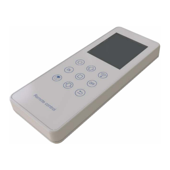
Product description The PRLCD remote control can read parameters from the machine, or set parameters to the machine. This remote control uses 2 AA dry batteries for power supply, and communicates with the controller by infrared/2.4G. Note: ①This remote control is only applicable to our seventh generation and later solar street light control and charging and discharging integrated machines. -
Page 4: Instructions
Sending Key: When the parameters are set, press this button, the remote control sends wireless data for parameter setting. Signal OFF Key: make the controller enter sleep state. Enter key: When modifying data, press this key to form a modification shadow and enter the modification mode. -
Page 5: Check System Info
3) Communication mode: There are currently three communication modes, infrared communication, 2.4G scanning and 2.4G broadcasting. The corresponding mode should be selected according to the communication mode of the controller. Communication distance: only valid for 2.4G scan mode and 2.4G broadcast mode, super far (48 meters), far (33 meters), normal (24 meters), near (15 meters), super near (3 meters) (Note: The above distance is tested when there is no obstruction between the controller and the remote control, and there will be some deviation from the actual use distance) - Page 6 5) The model of the current controller is automatically recognized by the remote control, and there is no need to select the model on the remote control. 3.2.2. Infrared communication: Point the remote control at the controller's infrared emitting tube and receiving tube. On the main interface, move the cursor to "real-time data"...
- Page 7 confirm after setting. Parameter setting interface Setup complete interface Search success interface 1) Press the send button to set the parameters of the searched controllers one by one. During the setting process, pressing any key at this time is invalid until the setting is completed, the success of the setting will be displayed behind the ID.
- Page 8 2) Press the shutdown button to set the shutdown settings for the controller with the current ID. When you hear a long beep from the controller, the LCD screen of the remote control will also display the transmission success, which means that the parameters have been written successfully.。...
-
Page 9: View Current Parameters
3.4.View current parameters 3.4.1. 2.4G Scanning: In the main interface, move the cursor to "Read Parameters" and press the "□" key to enter the search interface for reading parameters. If the interface prompts, press the search key, and press the search key to search for the controller ID (if part of the current search is found) Controller ID, you can also search again), after searching the controller ID, select the controller ID that needs to read the parameters, press the "□"... - Page 10 controller ID from small to large. 3) The search interface for real-time data, sending parameters, and reading parameters are synchronized. 4) The real-time data, sending parameters, and reading parameter interfaces can all be individually set for startup and shutdown. 5) When setting up the controller, make sure that besides the controller that needs to be set up, no other controllers are working, to avoid incorrect or under-setup.
- Page 11 11-12.5V: 100% light on the original setting 10.8-11V: On the basis of the original setting *85% 10.6-10.8V: On the basis of the original setting *70% 10.4-10.6V: On the basis of the original setting *55% 10.2-10.4V: On the basis of the original setting *40% 10-10.2V: On the basis of the original setting *25% 9-10V: minimum power drive light <9V: Enter under-voltage protection without driving lights...
- Page 12 Figure 3-12 Schematic diagram of remote control lock/unlock As shown in Figure 3-12 above, the user presses the three keys in the red box at the same time and hears a beep to lock the remote control; in the locked state, press these three keys at the same time, It can be unlocked after hearing the "di"...
-
Page 13: Controller Indicator Status List
Controller indicator status list The following table is a list of indicator lights. Users can judge the system status according to the flashing conditions of the indicator lights. If the system is faulty, the problem can be locked and solved according to the indicator status. Yellow Indicator Green Indicator Red Indicator... -
Page 14: Battery Parameter Setting (For Reference)
7. Battery parameter setting (for reference) Charge Battery Clean Light Start Super Rated Series voltage undervo undervo control saving saving Voltage ltage ltage voltage power power Lifepo4 12.8 14.4 10.8 12.5 25.6 28.8 21.6 8-10 Charge Battery Clean Light Start Super Rated Series...
Need help?
Do you have a question about the PRLCD and is the answer not in the manual?
Questions and answers