
Related Manuals for ATIM ARM-SE

Summary of Contents for ATIM ARM-SE
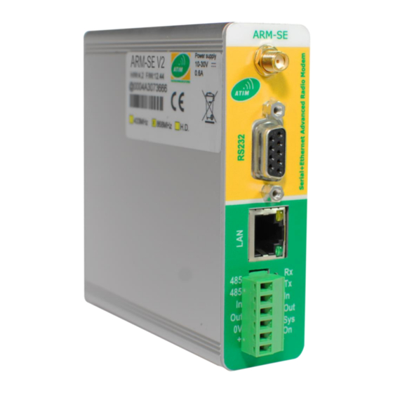
- Page 1 Advanced Radio Modules Serial / Ethernet radio Modem ARM-SE User Guide Concerned model: ARM/868-SE ATIM Radiocommunications www.atim.com Chemin des Guillets info@atim.com 38250 Villard de Lans France +33 4 76 95 50 65...
-
Page 2: Table Of Contents
ABLE OF ONTENTS Document version history ........................3 Disclaimer ..............................3 Trademarks and copyright........................3 Declaration of compliance ........................4 Environmental recommendations ......................4 Explosive atmosphere ......................... 4 Environment ............................4 Radio ..............................5 Generalities ............................. 6 Radio regulation ............................7 Context .............................. - Page 3 i. Setup ............................29 Repeater ..........................31 i. Synoptic ..........................31 ii. Filtering ..........................32 iii. Limitations ..........................32 iv. Setup ............................. 33 Gateway Modbus ........................ 34 i. Local target ..........................35 ii. Serial link target ........................35 iii. Target on remote radio modem ................... 35 iv.
-
Page 4: Document Version History
Trademarks and copyright ATIM radiocommunications®, ACW ATIM Cloud Wireless® and ARM Advanced Radio Modem® are registered trademarks of ATIM SARL in France. The other trademarks mentioned in this document are the property of their respective owners. ATIM_ARM-SE_UG_EN_V2.5... -
Page 5: Declaration Of Compliance
Declaration of compliance All ACW Atim Cloud Wireless® products comply with the regulatory requirements of the R&TTE Directive (1999/5/EC), article 3: 1 SAFETY (Article 3.1a of the 1999/5/EC Directive) NF EN60950-1 Ed. 2006/A1:2010/A11:2009/A12:2011 (health) EN62479: 2010 (power <20mW) or EN62311:2008 (power > 20mW) 2 Electromagnetic compatibility (Article 3.1b of the 1999/5/EC Directive) -
Page 6: Radio
General hazard – Failure to follow the instructions presents a risk of equipment damage. Electrical hazard – Failure to follow the instructions presents a risk of electrocution and physical injury. Direct-current symbol WARNING: do not install this equipment near any source of heat or any source of humidity. WARNING: for your safety, it is essential that this equipment be switched off and disconnected from mains power before carrying out any technical operation on it. -
Page 7: Generalities
ARM radio modems. Be sure to read this entire manual before operating an ARM-SE radio modem. This manual is part of the ARMSE radio modem and comes with it. The rules for the prevention of risks and accidents as well as the safety rules must be respected! 1. -
Page 8: Radio Regulation
R & TTE Directive are the responsibility of the manufacturer of the final product. A declaration of conformity for the radio module is available at ATIM on request. Applicable regulatory requirements are subject to change. ATIM does not take any responsibility for the accuracy and precision of the above information. - Page 9 Spectrum access and Modulation/ Power/Magnetic ECC/ERC Frequency Band mitigation maximum occupied Notes Field Decision requirements bandwidth ≤ 100 kHz for 47 or ≤ 0.1% duty cycle or 25 mW e.r.p. more channels (note FHSS LBT (notes 1 and 5) 25 mW e.r.p. Power ≤...
-
Page 10: Technical Characteristics
Puissance radio de 0 à 27dBm à 868Mhz Mode de Fonctionnement Ethernet, Série, Passerelle Configuration par Page Web Mode répéteur simple Contrôle radio LBT (Listen Before Talk) ARM-SE Dimensions 105 x 105 x 31 mm Antenna SMA Connector -20°C to +55°C (operating) Temperature -40°C à... - Page 11 Link interface Ethernet Interface Connector RJ45 10 Base T Isolated Interface RS232 SUB-D 9 female pins Interface RS485 Terminal block connector Serial link rate 1200 bps to 115000 bps MOSFET output +10/30 Vdc Time delays Modem wake-up time 3.2s Turnaround time Rx/Tx and Tx/Rx 2.4ms Time delays RS232 Rx/Tx and Tx/Rx Time delays RS485 Rx/Tx and Tx/Rx...
-
Page 12: Installation
2. Installation a) Warnings During installation please observe the following instructions: The power supply of the equipment must be connected to an electrical installation that complies with the standardization in force in the country (NFC 15-100 in France). It must be equipped with protections against overcurrent, over voltages, earth faults (maximum 16A rating). - Page 13 Antenna Low loss cable Ground Ground Ground Antenna connection The use of coaxial cable type RG58 (-1dB / m) is not recommended (high loss). ATIM_ARM-SE_UG_EN_V2.5...
-
Page 14: B) Antenna
b) Antenna A bad choice of antenna can have considerable consequences on the quality of the radio link. It is important to use a suitable antenna and, if necessary, a low loss cable to place it in a slightly obstructed area. -
Page 15: C) Mounting
c) Mounting On cabinet A.R.M. radio modems can be supplied with a ½ wave whip antenna angled so that the antenna is positioned vertically directly on the modem. This antenna is interesting if A.R.M. is mounted in a plastic box. In this case the antenna must not be placed against a metal plate (bottom plate for example). -
Page 16: Exterior Antenna (Mast)
Exterior antenna (mast) In this case, you can use the antenna referenced ANT868-BZ with a cable type CFP10 (low loss diameter 10mm). With this type of cable, you can deport the antenna 10 or 20m or more depending on the link budget (we can calculate it for you to know the distance between the two or more points, the type of antenna and the desired cable length). -
Page 17: D) Radiation Pattern
d) Radiation pattern « A radiation or emission diagram is the graphical representation of the spatial distribution of a quantity characterizing the radiation of a radio antenna ... The radiation pattern of an antenna makes it possible to visualize the emission lobes in all three dimensions, in the horizontal plane or in the vertical plane including the largest lobe. - Page 18 The antennas available in our catalog are characterized and their radiation patterns are known. Refer to the antenna user manuals to get the best out of your equipment. Vertical radiation Horizontal radiation ATIM_ARM-SE_UG_EN_V2.5...
-
Page 19: E) Alignment Of The Antenna
On the ARM-SE modems configuration web pages, it is possible to launch test tools to assess the positioning of the antennas. For this, use the transmitter-side pure transmitter emission tests and the receiver-side spectrum analyzer. -
Page 20: F) Radio Channel Selection
f) Radio channel selection The selection of the radio channel is normally done by the coding wheel placed at the rear of the modem otherwise by software configuration. This is only read when the power is turned on, so you must turn off the power, select the radio channel and switch on again for any change. -
Page 21: Connections And Links
3. Connections and links 6: TPIN- 4: TPIN+ 3: TPOUT- 1: TPOUT+ RS485- RS485+ 10 -> 30V Diagram of connection of the modem ATIM_ARM-SE_UG_EN_V2.5... -
Page 22: A) Power Supply
Power supply We recommend the use of our 24V reference ATIM power supply: ALIM220-24V-1A. The power supply must be near the radio modem. The cable for the power supply must be 3 conductors of section 0.5 (blue, brown, green / yellow) and maximum length 3m. -
Page 23: C) Ethernet Link
Ethernet link The ARM-SE modem must be connected to the network by CAT3 or CAT5 cross-over or cross-over cable in accordance with the network device to which it is connected. When switching on, the Orange LED on the RJ45 connector should light up. If this is not the case, check the conformity of the Ethernet cable. -
Page 24: E) Serial Link Rs485
e) Serial link RS485 It is possible to configure the radio modem and also to be able to communicate through this interface. The advantage of the RS485 is to be able to put several devices on the same 2-wire bus (A, B or respectively + and -). -
Page 25: F) Dry Contacts
Dry contacts The ARM-SE is equipped as standard with an input (IN) and a logic output (OUT). It can be controlled by Modbus function. Logical input Logical output ATIM_ARM-SE_UG_EN_V2.5... -
Page 26: Configuration
To access the modem configuration, the IP addresses of the modem and the PC must belong to the same class. Originally, the address class of the ARM-SE is 192.168.0; the station wanting to access its configuration must therefore have a similar address class. - Page 27 Note Beware of PCs with Wi-Fi controllers that can redirect Ethernet traffic on their media. It may be possible to disable this type of controller. Web pages using port 80, this port is normally released, by default, by the firewall. The advantage of an embedded configuration software is that it does not require any installation.
-
Page 28: B) Homepage And Password
Homepage and password @IP of the’ARM-SE by default: 192.168.0.25 Password: default The modem must be connected to a PC via an Ethernet cable in accordance with its network connection (straight or crossed). From an Internet browser, access the modem home page at 192.168.0.25. -
Page 29: Operating Mode
5. Operating mode a) Serie This mode of operation makes it possible to deport the information of a serial link RS232 or RS485 by radio. The interconnection of serial information and radio information is via buffer. Their size is: • Serial Buffer Tx: 256 octets •... -
Page 30: Setup
Setup On the Setup tab Choose the Serial operating mode Validate changes by Apply ATIM_ARM-SE_UG_EN_V2.5... - Page 31 On the Radio tab Choose the same channel as the remote modem (s). Choose Packet or Stream mode Choose the same radio rate as the remote modem (s). Basically, it is not necessary to configure the radio addressing. Do not activate the Wake On Radio mode. Validate changes by Apply ATIM_ARM-SE_UG_EN_V2.5...
-
Page 32: B) Repeater
Repeater Synoptic CHANNEL CHANNEL CHANNEL The repeater mode of the ARM-SE permanently switches to receive one radio channel. Any message received on one radio channel is broadcast on another radio channel. ATIM_ARM-SE_UG_EN_V2.5... -
Page 33: Filtering
Limitations The ARM-SE limits the size of repeated frames to 120 bytes. Only the packet mode is compatible with the repeater (see Radio tab> Data Formatting> Packet Mode). Using this mode induces longer communication times than in direct mode. -
Page 34: Setup
Setup Choose Repeater as the main mode of operation. Primary channel Primary filters Secondary channel Secondary filters Return received frames to the serial port Validate changes by Apply ATIM_ARM-SE_UG_EN_V2.5... -
Page 35: C) Gateway Modbus
In order to make these modes of communication compatible with each other from an Ethernet connection, the ARM-SE integrates a ModBus TCP / ModBus RTU gateway. The ARM-SE is then seen as a server queried by a client ModBus TCP application. To preserve maximum memory and performance, the user is asked to specify the number of client applications that connect to the ModBus TCP server. -
Page 36: Local Target
Target on remote radio modem This mode makes compatible the different modems of the ARM range with the ARM-SE. If the mode of operation of these is Modbus Slave, it is possible to interrogate them remotely and thus access all their features. -
Page 37: Settings
Operating Mode: Gateway Modbus Modbus modem slave identifier The Ethernet controller of the ARM-SE can apply some filters to avoid possible congestion of its buffer Query remote slaves (to be specified by checkbox) through the ARM-SE (via TCP port or Serial port) - Page 38 Validate changes by Apply ATIM_ARM-SE_UG_EN_V2.5...
- Page 39 Exceptions are returned by the server to the client when the request did not reach its target or when the target did not respond before a certain timeout. The ModBus TCP server on the ARM-SE as well as the ModBus RTU targets emit various types of exceptions to identify the source of the problem.
-
Page 40: Firmware Update
6. Firmware update In order to keep the ARM-SE firmware up to date, the modems include a "BootLoader" program that allows you to reinstall the main program. This reinstallation is done via the modem's Ethernet connection using the ENC_loader utility provided with the update package. Allow outgoing connections to your Firewall or disable it. - Page 41 7. De-validate the conditions of step 1 and restart the modem by clicking on "Reset LIA". Remark When a modem is updated, it automatically returns to the factory configuration. It is then necessary to re-parameterize it. ATIM_ARM-SE_UG_EN_V2.5...
-
Page 42: Update Of Embedded Web
7. Update of embedded web pages Lauching MS-DOS Commabds on Windows XP Launching MS-DOS commands under Windows 7 ATIM_ARM-SE_UG_EN_V2.5... - Page 43 Ftp connexion User Order Memory erase Loading (can last about 1 min) Successful loading MS-DOS commands for FTP transfer 1. Open an MS-DOS command prompt and move to the location of the armwpLxxx.bin file. (Example C: \ Documents and Settings \) 2.
-
Page 44: Save Parameters And Return To Factory Settings
8. Save parameters and return to factory settings It is possible to save the settings as a test file. 1. Open the configuration by web pages 2. Go to the Admin tab 3. Click on "Download config" and agree to save the file 4. -
Page 45: Radio Frequency Table
9. Radio frequency table Channel 19,2 38,4 57,6 115,2 Freq. 1,2 kbps 2,4 kbps 4,8 kbps 9,6 kbps kbps kbps kbps kbps dec. hex. 0000 863,0000 0001 863,0125 14dBm 14dBm 14dBm 0002 863,0250 14dBm 14dBm 14dBm 14dBm 0003 863,0375 14dBm 14dBm 14dBm 0004... - Page 46 Channel 19,2 38,4 57,6 115,2 Freq. 1,2 kbps 2,4 kbps 4,8 kbps 9,6 kbps kbps kbps kbps kbps dec. hex. 0028 863,5000 14dBm 14dBm 14dBm 14dBm 14dBm 14dBm 14dBm 0029 863,5125 14dBm 14dBm 14dBm 14dBm 002A 863,5250 14dBm 14dBm 14dBm 14dBm 002B 863,5375...
- Page 47 Channel 19,2 38,4 57,6 115,2 Freq. 1,2 kbps 2,4 kbps 4,8 kbps 9,6 kbps kbps kbps kbps kbps dec. hex. 0052 864,0250 14dBm 14dBm 14dBm 14dBm 14dBm 0053 864,0375 14dBm 14dBm 14dBm 14dBm 0054 864,0500 14dBm 14dBm 14dBm 14dBm 14dBm 0055 864,0625 14dBm...
- Page 48 Channel 19,2 38,4 57,6 115,2 Freq. 1,2 kbps 2,4 kbps 4,8 kbps 9,6 kbps kbps kbps kbps kbps dec. hex. 007C 864,5500 14dBm 14dBm 14dBm 14dBm 14dBm 14dBm 007D 864,5625 14dBm 14dBm 14dBm 14dBm 007E 864,5750 14dBm 14dBm 14dBm 14dBm 007F 864,5875 14dBm...
- Page 49 Channel 19,2 38,4 57,6 115,2 Freq. 1,2 kbps 2,4 kbps 4,8 kbps 9,6 kbps kbps kbps kbps kbps dec. hex. 00A6 865,0750 14dBm 14dBm 14dBm 14dBm 14dBm 00A7 865,0875 14dBm 14dBm 14dBm 14dBm 00A8 865,1000 14dBm 14dBm 14dBm 14dBm 14dBm 14dBm 00A9 865,1125...
- Page 50 Channel 19,2 38,4 57,6 115,2 Freq. 1,2 kbps 2,4 kbps 4,8 kbps 9,6 kbps kbps kbps kbps kbps dec. hex. 00D0 865,6000 14dBm 14dBm 14dBm 14dBm 14dBm 14dBm 00D1 865,6125 14dBm 14dBm 14dBm 14dBm 00D2 865,6250 14dBm 14dBm 14dBm 14dBm 00D3 865,6375 14dBm...
- Page 51 Channel 19,2 38,4 57,6 115,2 Freq. 1,2 kbps 2,4 kbps 4,8 kbps 9,6 kbps kbps kbps kbps kbps dec. hex. 00FA 866,1250 14dBm 14dBm 14dBm 14dBm 14dBm 00FB 866,1375 14dBm 14dBm 14dBm 14dBm 00FC 866,1500 14dBm 14dBm 14dBm 14dBm 14dBm 00FD 866,1625 14dBm...
- Page 52 Channel 19,2 38,4 57,6 115,2 Freq. 1,2 kbps 2,4 kbps 4,8 kbps 9,6 kbps kbps kbps kbps kbps dec. hex. 0124 866,6500 14dBm 14dBm 14dBm 14dBm 14dBm 14dBm 0125 866,6625 14dBm 14dBm 14dBm 14dBm 0126 866,6750 14dBm 14dBm 14dBm 14dBm 0127 866,6875 14dBm...
- Page 53 Channel 19,2 38,4 57,6 115,2 Freq. 1,2 kbps 2,4 kbps 4,8 kbps 9,6 kbps kbps kbps kbps kbps dec. hex. 014E 867,1750 14dBm 14dBm 14dBm 14dBm 14dBm 014F 867,1875 14dBm 14dBm 14dBm 14dBm 0150 867,2000 14dBm 14dBm 14dBm 14dBm 14dBm 0151 867,2125 14dBm...
- Page 54 Channel 19,2 38,4 57,6 115,2 Freq. 1,2 kbps 2,4 kbps 4,8 kbps 9,6 kbps kbps kbps kbps kbps dec. hex. 0178 867,7000 14dBm 14dBm 14dBm 14dBm 14dBm 14dBm 14dBm 0179 867,7125 14dBm 14dBm 14dBm 14dBm 017A 867,7250 14dBm 14dBm 14dBm 14dBm 017B 867,7375...
- Page 55 Channel 19,2 38,4 57,6 115,2 Freq. 1,2 kbps 2,4 kbps 4,8 kbps 9,6 kbps kbps kbps kbps kbps dec. hex. 01A2 868,2250 14dBm 14dBm 14dBm 14dBm 14dBm 01A3 868,2375 14dBm 14dBm 14dBm 14dBm 01A4 868,2500 14dBm 14dBm 14dBm 14dBm 14dBm 01A5 868,2625 14dBm...
- Page 56 Channel 19,2 38,4 57,6 115,2 Freq. 1,2 kbps 2,4 kbps 4,8 kbps 9,6 kbps kbps kbps kbps kbps dec. hex. 01CC 868,7500 14dBm 14dBm 14dBm 14dBm 14dBm 14dBm 01CD 868,7625 14dBm 14dBm 14dBm 14dBm 01CE 868,7750 14dBm 14dBm 14dBm 14dBm 01CF 868,7875 14dBm...
- Page 57 Channel 19,2 38,4 57,6 115,2 Freq. 1,2 kbps 2,4 kbps 4,8 kbps 9,6 kbps kbps kbps kbps kbps dec. hex. 01F6 869,2750 14dBm 14dBm 14dBm 14dBm 14dBm 01F7 869,2875 14dBm 14dBm 14dBm 14dBm 01F8 869,3000 14dBm 14dBm 14dBm 14dBm 14dBm 14dBm 01F9 869,3125...
- Page 58 Channel 19,2 38,4 57,6 115,2 Freq. 1,2 kbps 2,4 kbps 4,8 kbps 9,6 kbps kbps kbps kbps kbps dec. hex. 0220 869,8000 14dBm 14dBm 14dBm 14dBm 14dBm 0221 869,8125 14dBm 14dBm 14dBm 14dBm 0222 869,8250 14dBm 14dBm 14dBm 14dBm 0223 869,8375 14dBm 14dBm...
Need help?
Do you have a question about the ARM-SE and is the answer not in the manual?
Questions and answers