
Summary of Contents for HWS Intesis INMBSOCP0010100
- Page 1 Modbus Server Open Charge Point Protocol (OCPP) USER MANUAL Issue date: 03/2021 r1.4 ENGLISH...
- Page 2 Modbus – OCPP ® Intesis User Manual r1.4 eng Important User Information Disclaimer The information in this document is for informational purposes only. Please inform HMS Industrial Networks of any inaccuracies or omissions found in this document. HMS Industrial Networks disclaims any responsibility or liability for any errors that may appear in this document.
- Page 3 Modbus – OCPP ® Intesis User Manual r1.4 eng Gateway for the integration of OCPP Charging Points into Modbus TCP or RTU enabled systems and external OCPP Central Systems ORDER CODES LEGACY ORDER CODE INMBSOCP0010100 INMBSOCP0200100 © HMS Industrial Networks S.L.U - All rights reserved https://www.intesis.com This information is subject to change without notice 3 / 18...
-
Page 4: Table Of Contents
Modbus – OCPP ® Intesis User Manual r1.4 eng INDEX 1 Description ............................... 5 Introduction ............................5 Functionality ............................. 6 Gateway’s capacity .......................... 6 2 Modbus interface ............................7 Description ............................7 Functions supported ......................... 7 Modbus TCP ............................. 7 Modbus RTU ............................ -
Page 5: Description
Modbus – OCPP ® Intesis User Manual r1.4 eng 1 Description Introduction This document describes how to integrate OCPP devices (EV Chargers) into Modbus TCP and RTU compatible devices and systems, or into an external OCPP Central System (CS), through Intesis Modbus - OCPP gateway. An assumption is made that the user is familiar with Modbus and OCPP technologies and their technical terms. -
Page 6: Functionality
Modbus – OCPP ® Intesis User Manual r1.4 eng Functionality The configuration tool for this gateway is Intesis® MAPS software. For a detailed information about the necessary steps to integrate the gateway in a Modbus BMS, please review the Intesis Configuration Guide for more information. Available in www.intesis.com From the OCPP system standpoint, after the start up process, all EV Chargers will try to connect with Intesis gateway... -
Page 7: Modbus Interface
Modbus – OCPP ® Intesis User Manual r1.4 eng 2 Modbus interface Description Intesis acts as a server device in its Modbus TCP or RTU interface, connecting to the Ethernet port of the gateway or the RS485 port. To access the points and resources of the Intesis from a Modbus client/master device, see details below in this document. -
Page 8: Points Definition
Modbus – OCPP ® Intesis User Manual r1.4 eng Points definition Every point defined in the gateway has the Modbus Format, Point and R/W features associated to it. Each point defined in Intesis has the following Modbus features associated to it: Feature Description #Bits... -
Page 9: Connections
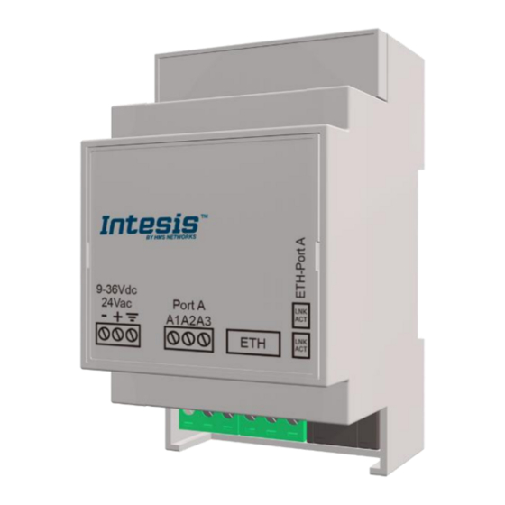
Modbus – OCPP ® Intesis User Manual r1.4 eng 3 Connections Find below information regarding the Intesis connections available. Power Supply Must use NEC Class 2 or Limited Power Source (LPS) and SELV rated power supply. Respect polarity applied of terminals (+) and (-). Be sure the voltage applied is within the range admitted (check table below). -
Page 10: Powering The Device
Modbus – OCPP ® Intesis User Manual r1.4 eng Powering the device A power supply working with any of the voltage range allowed is needed (check section 5). WARNING! To avoid earth loops that can damage the gateway and/or any other equipment connected to it, we strongly recommend: •... -
Page 11: Set-Up Process And Troubleshooting
Modbus – OCPP ® Intesis User Manual r1.4 eng 4 Set-up process and troubleshooting Pre-requisites It is necessary to have a Modbus TCP client or RTU master device operative and properly connected to the corresponding Modbus port of Intesis and OCPP devices connected to its corresponding ports as well. An External OCPP system is required in the system if the External OCPP Central System functionality is enabled. -
Page 12: Configuration Tab
Modbus – OCPP ® Intesis User Manual r1.4 eng 4.2.3 Configuration tab Select the Configuration tab to configure the connection parameters. Three subsets of information are shown in this window: General (Gateway general parameters), Modbus slave (Modbus TCP and RTU interface configuration) and OCPP (OCPP configuration and devices parameters). - Page 13 Modbus – OCPP ® Intesis User Manual r1.4 eng The OCPP Configuration window allows for the following settings: • OCPP type: select the OCPP mode for the gateway BMS Central System: Gateway and BMS act as an OCPP Central System External Central System: Gateway acts as a bridge between an external OCPP CS and OCPP chargers ▪...
-
Page 14: Signals
Modbus – OCPP ® Intesis User Manual r1.4 eng 4.2.4 Signals All available OCPP signals, its corresponding Modbus register and other main parameters are listed in the signals tab. More information on each parameter and how to configure it can be found in the Intesis MAPS user manual. Figure 4.6 Intesis MAPS Signals tab NOTE: Depending on the OCPP mode selected in Configuration, signals list and displayed properties will vary. -
Page 15: Diagnostic
Modbus – OCPP ® Intesis User Manual r1.4 eng 4.2.6 Diagnostic To help integrators in the commissioning tasks and troubleshooting, the Configuration Tool offers some specific tools and viewers. To start using the diagnostic tools, connection with the Gateway is required. The Diagnostic section is composed by two main parts: Tools and Viewers. -
Page 16: Set-Up Procedure
Modbus – OCPP ® Intesis User Manual r1.4 eng Set-up procedure 1. Install Intesis MAPS on your laptop, use the setup program supplied for this and follow the instructions given by the Installation wizard. 2. Install Intesis in the desired installation site. Installation can be on DIN rail or on a stable not vibrating surface (DIN rail mounted inside a metallic industrial cabinet connected to ground is recommended). -
Page 17: Electrical & Mechanical Features
Modbus – OCPP ® Intesis User Manual r1.4 eng 5 Electrical & Mechanical Features Plastic, type PC (UL 94 V-0) Net dimensions (d h): 93x53x58 mm Enclosure Recommended space for installation (d h): 100x60x70mm Color: Light Grey. RAL 7035 Wall. Mounting DIN rail EN60715 TH35. -
Page 18: Dimensions
Modbus – OCPP ® Intesis User Manual r1.4 eng 6 Dimensions 58 mm (h) 53 mm (w) 93 mm (d) Recommended available space for its installation into a cabinet (wall or DIN rail mounting), with space enough for external connections 70 mm (h) 100 mm (d) 60 mm (w)
Need help?
Do you have a question about the Intesis INMBSOCP0010100 and is the answer not in the manual?
Questions and answers