Advertisement
Quick Links
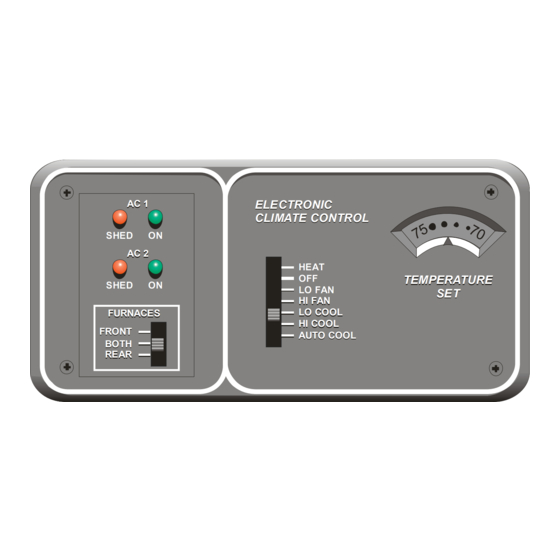
ELECTRONIC CLIMATE CONTROL II
SERVICE MANUAL Part No's. 00-00855-000 / 00-00856-000
Product Description
The ELECTRONIC CLIMATE CONTROL II (ECC2) System offers automatic and manual control of the A/C1 and A/C2
roof-top air conditioners and furnace/s in the motor home. The system includes an energy management system that
shuts off the air conditioners, when necessary, to prevent electrical over-load. It also includes a number of features that
provide the owner with the most comfortable temperature controlled environment possible.
In the HEAT mode, the system offers automatic control of the furnace/s in a manner identical to standard wall mount
thermostats.
In either the LOW COOL or HIGH COOL modes, the air conditioner fans run continuously at the selected speed and the
compressors are controlled to maintain the set point temperature. When in the AUTO mode, the unit automatically
controls the compressors and selects the appropriate air conditioner fan speed based on the difference between the set
point temperature and the ambient temperature in the motor home.
In addition to controlling the temperature within the coach, the system constantly monitors the current being drawn by all
of the 120 VAC electrical appliances, including the air conditioners, and will control the operation of the air conditioners to
prevent them from over-loading the circuit breakers. Once the system turns the air conditioners off, it will keep them off
until there is enough power available to restore normal operation.
The system has been designed to operate from 120 VAC, 30 Amp service only. Connecting the coach to any other
power source will cause the system to operate improperly. If only 20 Amp service is available, "load management" must
be done manually by the owner, and only one air conditioner can be operated at a time, unless the auxiliary generator is
utilized.
Intellitec
www.Intellitec.com
AC 1
AC 1
SHED
SHED
ON
ON
AC 2
AC 2
SHED
SHED
ON
ON
FURNACES
FURNACES
FRONT
FRONT
BOTH
BOTH
REAR
REAR
ELECTRONIC
ELECTRONIC
CLIMATE CONTROL
CLIMATE CONTROL
HEAT
HEAT
OFF
OFF
LO FAN
LO FAN
HI FAN
HI FAN
LO COOL
LO COOL
HI COOL
HI COOL
AUTO COOL
AUTO COOL
- 1 -
TEMPERATURE
TEMPERATURE
SET
SET
1485 Jacobs Rd.
Deland, FL 32724
P/N 53-00855-856 Rev. C 080819
386.738.7307
Advertisement

Subscribe to Our Youtube Channel
Summary of Contents for Intellitec ELECTRONIC CLIMATE CONTROL II
- Page 1 REAR Product Description The ELECTRONIC CLIMATE CONTROL II (ECC2) System offers automatic and manual control of the A/C1 and A/C2 roof-top air conditioners and furnace/s in the motor home. The system includes an energy management system that shuts off the air conditioners, when necessary, to prevent electrical over-load. It also includes a number of features that provide the owner with the most comfortable temperature controlled environment possible.
- Page 2 ELECTRONIC CLIMATE CONTROL II SERVICE MANUAL Part No’s. 00-00855-000 / 00-00856-000 How It Works The System contains two major components, the ECC Thermostat and the ECC Control Module, along with additional external sensors which are connected to these modules. THE ECC THERMOSTAT: The Thermostat allows the owner to set the air conditioning and heating systems’...
-
Page 3: Indicator Lights
ELECTRONIC CLIMATE CONTROL II SERVICE MANUAL Part No’s. 00-00855-000 / 00-00856-000 LOW COOL - The air conditioner fans are energized on low speed. The compressor for A/C 1 turns on when the ambient temperature at the front temperature probe exceeds the set temperature, and stays on until that temperature is reduced below the set temperature. - Page 4 ELECTRONIC CLIMATE CONTROL II SERVICE MANUAL Part No’s. 00-00855-000 / 00-00856-000 THE ECC CONTROL MODULE: The control module performs the timing, sequencing, switching, and load shedding functions for the furnace/s, air conditioner fans and compressors. It is often located under the refrigerator. The circuitry in this module decodes the control signals sent to it via the multiplexed communication link, IPX, from the ECC Thermostat.
- Page 5 ELECTRONIC CLIMATE CONTROL II SERVICE MANUAL Part No’s. 00-00855-000 / 00-00856-000 VDC) wiring. The Control Module uses high-side switching to operate the corresponding relays. One side of each of the relay coils is connected together. This ”common” lead is connected to ground through the Control Module and should not be grounded anywhere else.
-
Page 6: Load Shedding
ELECTRONIC CLIMATE CONTROL II SERVICE MANUAL Part No’s. 00-00855-000 / 00-00856-000 they are shorted, the system will not operate. To help diagnose a fault with this line, the control module includes two LED indicators, “IPX OK” and “IPX FAULT”, associated with this circuit. Under normal operation, the “IPX OK” light should be lit. -
Page 7: System Interconnects
ELECTRONIC CLIMATE CONTROL II SERVICE MANUAL Part No’s. 00-00855-000 / 00-00856-000 SYSTEM INTERCONNECTS: 12 VDC power is supplied to the control module via connector J1. This connector also provides the signal connections between the control module and thermostat and the current sensor. Connector PC1B is part of the current sensor assembly. - Page 8 ELECTRONIC CLIMATE CONTROL II SERVICE MANUAL Part No’s. 00-00855-000 / 00-00856-000 BREAKER BOX CURRENT SENSOR MAIN 30 AMP SHORE POWER CORD CHANGE- OVER 120VAC LINE SENSOR RELAY CONTROLLED 87-01001-112 AIR CONDITIONER A/C2 LOW VOLTAGE WIRING LOW VOLTAGE CONTROL WIRING MODULE...
- Page 9 ELECTRONIC CLIMATE CONTROL II SERVICE MANUAL Part No’s. 00-00855-000 / 00-00856-000 Symptom Possible Cause / Remedy No green “ON” indicator, Thermostat in any functional Reset circuit breakers in Main distribution box. position Diagnostic “IPX OK” LED on the control module is NOT on: If “IPX FAULT”...
- Page 10 ELECTRONIC CLIMATE CONTROL II SERVICE MANUAL Part No’s. 00-00855-000 / 00-00856-000 “ON” indicator is lit, but the A/C compressor never A. Slide the test switch on the control module towards J2. comes on in either the LOW COOL, HIGH COOL, or A/C1 compressor and high fan should turn on.
- Page 11 ELECTRONIC CLIMATE CONTROL II SERVICE MANUAL Part No’s. 00-00855-000 / 00-00856-000 “ON” indicator is lit, but the furnace does not operate A. Check the fuse or circuit breaker feeding the furnace. in HEAT mode at any thermostat setting. B. Move the set point control up to the highest and down to the lowest temperature settings.
- Page 12 ELECTRONIC CLIMATE CONTROL II SERVICE MANUAL Part No’s. 00-00855-000 / 00-00856-000 1485 Jacobs Rd. Intellitec Deland, FL 32724 386.738.7307 www.Intellitec.com - 12 - P/N 53-00855-856 Rev. C 080819...
- Page 13 ELECTRONIC CLIMATE CONTROL II SERVICE MANUAL Part No’s. 00-00855-000 / 00-00856-000 PART DESCRIPTION INTELLITEC FLEETWOOD PART NUMBER PART NUMBER Single Furnace Thermostat 00-00856-_10 F80-0026 Dual Furnace Thermostat 00-00856-_00 Control Module 00-00855-000 F97-00XX (11k/13.5k BTU air conditioner) Current Sensor 01-00703-200 F93-2000...
- Page 14 ELECTRONIC CLIMATE CONTROL II SERVICE MANUAL Part No’s. 00-00855-000 / 00-00856-000 1485 Jacobs Rd. Intellitec Deland, FL 32724 386.738.7307 www.Intellitec.com - 14 - P/N 53-00855-856 Rev. C 080819...
Need help?
Do you have a question about the ELECTRONIC CLIMATE CONTROL II and is the answer not in the manual?
Questions and answers