
Subscribe to Our Youtube Channel
Related Manuals for MEN Mikro Elektronik NM30

Summary of Contents for MEN Mikro Elektronik NM30
- Page 1 20NM30-00 E4 2017-01-11 NM30 Fully Managed 8-Port Rugged Ethernet Switch IP40 Industrial Stand-Alone Device User Manual...
-
Page 2: Table Of Contents
2.3.2 Wall-Mounting the NM30 ........21 2.3.3 Horizontal Mounting . - Page 3 Mounting the NM30 overhead........
-
Page 4: About This Document
This user manual is intended only for system developers and integrators, it is not intended for end users. It describes the design, functions and connection of the product. The manual does not include detailed information on individual components (data sheets etc.). NM30 product page with up-to-date information and downloads: www.men.de/products/nm30/ History Issue... - Page 5 About this Document Conventions Indicates important information or warnings concerning situations which could result in personal injury, or damage or destruction of the component. Indicates important information concerning electrostatic discharge which could result in damage or destruction of the component. Indicates important information or warnings concerning proper functionality of the product described in this document.
-
Page 6: Product Safety
Product Safety Product Safety Electrostatic Discharge (ESD) Computer boards and components contain electrostatic sensitive devices. Electrostatic discharge (ESD) can damage components. To protect the PCB and other components against damage from static electricity, you should follow some precautions whenever you work on your computer. Power down and unplug your computer system when working on the ... -
Page 7: Legal Information
Legal Information Legal Information Changes MEN Mikro Elektronik GmbH ("MEN") reserves the right to make changes without further notice to any products herein. Warranty, Guarantee, Liability MEN makes no warranty, representation or guarantee of any kind regarding the suitability of its products for any particular purpose, nor does MEN assume any liability arising out of the application or use of any product or circuit, and specifically disclaims any and all liability, including, without limitation, consequential or incidental damages. - Page 8 Nevertheless, MEN is registered as a manufacturer in Germany. The registration number can be provided on request. Copyright © 2017 MEN Holding. All rights reserved. Germany France China MEN Mikro Elektronik GmbH MEN Mikro Elektronik SAS MEN Micro Inc. MEN Mikro Elektronik Neuwieder Straße 3-7 18, rue René Cassin 860 Penllyn Blue Bell Pike (Shanghai) Co., Ltd.
-
Page 9: Product Overview
EN50155 class S2 requirements for voltages ranging 24 to 110 VDC. Conduction Cooled The NM30 is designed for fanless operation at temperatures ranging from -40 to +70°C. The NM30 features IP40 protection when surface-mounted and cooling fins which serve as a heatsink for the internal electronics, and in this way provides conduction cooling. -
Page 10: External Interfaces
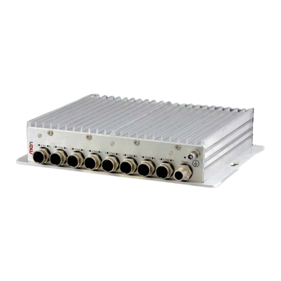
Product Overview External Interfaces Figure 1. Front interfaces Earthing Stud Wide range power supply (14.4‐154 VDC) M12 Ethernet connectors Figure 2. Rear interfaces RS232 Service console 20NM30-00 E4 2017-01-11 Page 10 ... -
Page 11: Block Diagram
Product Overview Block Diagram Figure 3. Block diagram Flash 10/100 BaseT Ethernet 10/100/1000 BaseT Ethernet 10/100 BaseT Ethernet 10/100/1000 BaseT Ethernet 10/100 BaseT Ethernet 10/100/1000 BaseT Ethernet Vitesse Ethernet Switch 10/100 BaseT Ethernet 10/100/1000 BaseT Ethernet 10/100 BaseT Ethernet 10/100/1000 BaseT Ethernet 10/100 BaseT Ethernet 10/100/1000 BaseT Ethernet 10/100 BaseT Ethernet 10/100/1000 BaseT Ethernet RS232 Service ... -
Page 12: Technical Data
8x 10/100/1000BASE-T fully managed switch with A-coded connectors (Model: 09NM30-02) 8x 10/100/1000BASE-T fully managed switch with X-coded connectors (Model: 09NM30-04) See the MEN website for available standard configurations: www.men.de/products/nm30/#ord Protocols and Functionality IEEE 802.3 for 10BASE-T IEEE 802.3u for 100BASE-T ... - Page 13 Product Overview Switch Management and Monitoring Link OAM: IEEE 802.3ah (a.k.a. EFM) CFM: IEEE 802.1ag ITU-T Y.1731 Down-MEP, ITU-T Y.1731 Up-MEP, ITU-T Y.1731 MIP MEF E-LMI Configuration Management SMAC/DMAC Swap OAM Performance Monitoring MEF35 Phase 1 SNMP Management v1, v2c, v3 (RFC 1212, 1901-1908, 3411-3418) ...
- Page 14 Product Overview Security Network Access Server (NAS): Port-based IEEE 802.1x Single and multiple IEEE 802.1x MAC based authentication VLAN and QOS assignment Guest VLAN RADIUS accounting (RFC 2866ff) MAC address limit and MAC freeze IP MAC Binding / Binfind dynamic to static ...
- Page 15 Product Overview DCSP remarking (RFC 2474) QoS control list (QCL mode)) Random Early Detection (RED, RFC 2309) Policers (port, service, queue and global/VCAP - ACL) DiffServ (RFC 2474) and Tag remarking Synchronization NTPv4 Client (RFC 5005) ...
- Page 16 Product Overview Weight 10/100BASE-T managed switch: 1400 g 10/100/1000BASE-T managed switch: 1500 g Environmental Specifications IP protection IP40 when surface-mounted Temperature range (operation) -40°C to 70°C (screened), with up to 85°C for 10 minutes according to class Tx (EN 50155) Fanless operation Temperature range (storage): -40°C to +85°C...
-
Page 17: Product Identification
Product Identification MEN user documentation may describe several different models and/or design revisions of the NM30. You can find information on the article number, the design revision and the serial number on a label affixed to the chassis. Article number: Indicates the product family and model. This is also MEN’s order- ... -
Page 18: Getting Started
Getting Started Getting Started Unpacking the NM30 After unpacking, check whether there are any transport or other damages on the system. If one of the following situations arises, have the equipment checked by service personnel: The power cable or plug is damaged. -
Page 19: Mounting The Nm30
Before installing the NM30, make sure that the installation site has been prepared and that the operating environment meets the equipment requirements. The NM30 network box has been designed to either sit on a flat surface or be securely mounted to a wall or similar surface. -
Page 20: Safety Instructions For Mounting
Getting Started 2.3.1 Safety Instructions for Mounting Risk of Damages or Injuries Make sure that the cabinet or the wall where you want to install the system supports the weight of the system. Do not put the system on top of other equipment. When the system ... -
Page 21: Wall-Mounting The Nm30
Getting Started 2.3.2 Wall-Mounting the NM30 When mounting the NM30 to a wall, first ensure that the wall surface has been prepared and that the mounting screws have been installed as listed below: » Ensure that the mounting location provides at least 15 cm of space around the net- work box housing to ensure correct ventilation for cooling. -
Page 22: Horizontal Mounting
3.5 mm between the surface and the screw head. » Place the NM30 so that the wide openings of the mounting holes are over the screw heads, then slide the box forward or backward so that the screw heads slip into the narrow part of the mounting hole. -
Page 23: Connecting And Starting
Read all labels and warnings on the equipment carefully; especially the power con- figuration and coding label affixed to the system chassis. » Adhere to the following safety instructions before you connect the NM30: Works on the computer system may only be carried out by personnel ... -
Page 24: Connecting An Earthing Cable
Getting Started 2.4.2 Connecting an Earthing Cable The NM30 features an earthing connection. Connect the earthing cable before making any other connections! A protective earth connection is essential for the system to meet its EMC specifications. When disassembling the system, always detach the earthing cable last. -
Page 25: Starting Up The System
Getting Started 2.4.3 Starting Up the System The switch is delivered with installed firmware and is a standalone, smart managed Ethernet switch that does not require any external software. It features a HTTP Web interface for configuring the firmware. Chapter 2.5 Accessing the Ethernet Switch on page 26 for more information on accessing the switch. -
Page 26: Accessing The Ethernet Switch
Getting Started Accessing the Ethernet Switch Once the system has powered up, you can access the switch using its base address with telnet, ssh, http, https or the service console interface. 2.5.1 Web Interface The web interface provides an online help option for all configuration sheets which can be accessed by clicking on the question mark in the top right corner of the screen: Figure 8. -
Page 27: Figure 9. Command Line Interface
Getting Started Figure 9. Command line interface Chapter 1.4 Technical Data on page 12 for more information on the switch matrix and included protocols. 20NM30-00 E4 2017-01-11 Page 27 ... -
Page 28: Starting Up The Switch
Displaying the current configuration and saving to Flash storage The NM30 switch must be powered on and have a functional computer connection using the serial console port on the device (115 200 baud, no parity, 8 data bits, 1 stop bit, no flow control). -
Page 29: Setting A Password For The Admin User
Getting Started » Type configure terminal then press <Enter> » Type hostname my-device and press <Enter> (replace my-device with a suitable name) » Finally type exit and press <Enter> configure terminal (config)# hostname my-device my-device(config)# exit my-device# The commands are executed immediately, so hostname changes the device hostname right away as is reflected in the prompt. -
Page 30: Displaying And Saving The Configuration
Getting Started The prompt will change as the interface vlan 1 command enters a configuration sub- mode that allows, among other things, the configuration of the IP address. Also note that IP addresses can only be assigned to VLAN interfaces. After configuration is complete, the resulting IP address can be inspected. - Page 31 Getting Started The command show running-config will display the configuration settings as seen below (the set of interfaces is dependent on hardware capabilities). my-device# show running-config Building configuration... hostname my-device username admin privilege 15 password encrypted dmVyeS1zZWNyZXQ= vlan 1 name default spanning-tree mst name 00-01-c1-00-ad-80 revision 0 ! [...] interface GigabitEthernet 1/1...
- Page 32 Getting Started The configuration as displayed above is saved in the startup-config file. my-device# copy running-config startup-config Building configuration... % Saving 1326 bytes to flash:startup-config my-device# dir Directory of flash: r- 1970-01-01 00:00:00 648 default-config rw 1970-01-03 18:21:28 1326 startup-config 2 files, 1974 bytes total.
-
Page 33: Functional Description
Power-up sequencing Three independent channels to generate the required onboard voltages 3.1.2 Power Status LED The NM30 provides a power status LED to indicate that all internal voltages are good. Table 4. Power status LED LEDs Description Color... -
Page 34: Ethernet
Functional Description Ethernet Only mating connectors with a maximum diameter of 19 mm can be used on the NM30. 3.2.1 Fast Ethernet D-Coded Table 5. Connector types – M12 D-Coded Connector Type On NM30 4-pin M12 receptacle, D-coded (SACC-CI-M12FSD-4CON-L180-THR -... -
Page 35: Gigabit Ethernet A-Coded
3.2.2 Gigabit Ethernet A-Coded Table 8. Connector types – Ethernet M12 A-coded Connector Type On NM30 8-pin M12 receptacle, A-coded (SACC-CI-M12FS-8CON-L180-THR - 1557808) Mating 8-pin M12 plug, A-coded (Phoenix Contact SACC-M12MS-8Q SH - 1543236 (straight)) 8-pin M12 plug, A-coded (Phoenix Contact SACC-M12MR-8Q SH - 1553653 (angled)) Table 9. -
Page 36: Gigabit Ethernet X-Coded
3.2.3 Gigabit Ethernet X-Coded Table 11. Connector types – Ethernet M12 Connector Type On NM30 8-pin M12 receptacle, X-coded (SACC-CI-M12FS-8CON-L180-10G - 1402457) Mating 8-pin M12 plug, X-coded (Phoenix Contact VS-08-M12MS-10G-P SCO - 1417430 (straight)) 8-pin M12 plug, X-coded (Phoenix Contact VS-08-M12MR-10G-P SCO - 1417443 (angled)) Table 12. -
Page 37: Ethernet Status Leds
Functional Description 3.2.4 Ethernet Status LEDs The NM30 provides a total of sixteen Ethernet status LEDs, two for each Ethernet channel. They signal the link and activity status. Figure 10. Position of Ethernet status LEDs Table 14. Ethernet status LEDs... -
Page 38: Table 16. Connector Types - Rs232 M12
Functional Description RS232 The NM30 provides a RS232 service console which is used for local system management, configuration and maintenance purposes. An external dongle can also be connected to the service port for switch configuration. Table 16. Connector types – RS232 M12...
Need help?
Do you have a question about the NM30 and is the answer not in the manual?
Questions and answers