Table of Contents
Advertisement
Quick Links
Advertisement
Table of Contents

Summary of Contents for H&B LDU 179.1
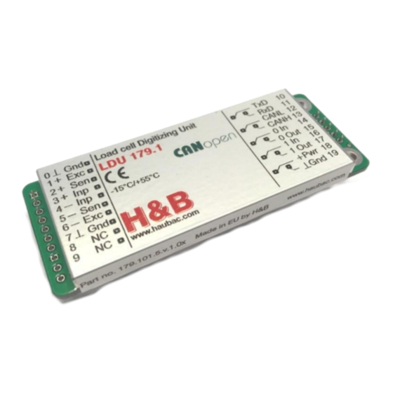
- Page 1 Type LDU 179.1 ECHNICAL ANUAL Firmware Version 179.181.v.1.10 or higher Hardware Version 179.101.5.v.1.01 Document No. X179 Rev 1.1 EN Hauch & Bach ApS Femstykket 6 DK-3540 Lynge Denmark www.haubac.com LDU 179.1 Technical Manual rev. 1.10 - February 2019 Page 1 of 45...
-
Page 2: Table Of Contents
FD Reset to Factory Default Settings ......................26 8.2.11. Correction of System Zero ........................26 8.2.12. ZR Zero Range .............................. 27 8.2.13. ZI Initial Zero Range ............................27 8.2.14. Tare mode ............................. 27 LDU 179.1 Technical Manual rev. 1.10 - February 2019 Page 2 of 45... - Page 3 8.12.4. TE Trigger Edge ............................. 41 8.12.5. TR Software Trigger ............................42 8.12.6. TL Trigger Level ............................. 42 8.12.7. SA Send Triggered Average Value automatically ..................42 LDU 179.1 Technical Manual rev. 1.10 - February 2019 Page 3 of 45...
- Page 4 Short-time Averaging Period........................43 8.13.5. TW Window for Automatic Taring ........................44 8.13.6. TI Averaging Time for Automatic Taring ......................44 Use in “Approved” Applications ......................45 LDU 179.1 Technical Manual rev. 1.10 - February 2019 Page 4 of 45...
-
Page 5: Safety Instructions
CONNECTIONS OR DISCONNECTIONS ARE MADE. FAILURE TO OBSERVE THESE PRECAUTIONS COULD RESULT IN DAMAGE TO OR DESTRUCTION OF THE EQUIPMENT OR BODILY HARM. CAUTION OBSERVE PRECAUTIONS FOR HANDLING ELECTROSTATIC SENSITIVE DEVICES. LDU 179.1 Technical Manual rev. 1.10 - February 2019 Page 5 of 45... -
Page 6: Declaration Of Conformity
Metrologische Aspekte nichtselbsttätiger Waagen; Deutsche Fassung EN 45501:2015 DIN EN Anhang B.3: Funktionsprüfungen unter Störeinflüssen 45501 Anhang C: Verfahren für die Prüfung der Störfestigkeit gegen hochfrequente elektromagnetische Felder. Michael Bach Managing Director LDU 179.1 Technical Manual rev. 1.10 - February 2019 Page 6 of 45... -
Page 7: Introduction And Specifications
ASCII command set. The LDU 179.1 and the well known LDU 78.1, both use nearly the same command set. The LDU 179.1 with its accurate A to D converter and a sample rate of up to 1200 measurement values per second, is particularly suitable for static or dynamic measurements and control purposes. -
Page 8: Communications And Getting Started
Factory default: 115200 baud 4.2. Command Language The command set of the LDU 179.1 is based on a simple ASCII format (2 letters). This enables the user to setup the device, get results or check parameters. Example: LDU 179.1 is connected via the RS232 port to a PC / PLC system. You want to get the identity, firmware version or net weight. -
Page 9: Hardware And Wiring
Out 0 Logical output 0 – Excitation In 1 Logical input 1 Shield Out 1 Logical output 1 + Pwr Power supply +10..+30 VDC Power supply - LDU 179.1 Technical Manual rev. 1.10 - February 2019 Page 9 of 45... -
Page 10: Load Cell Connection
: Close to enter configuration mode. : Do NOT close – used for program download only. : This switch can connect the power supply ground to the shield. LDU 179.1 Technical Manual rev. 1.10 - February 2019 Page 10 of 45... -
Page 11: Canopen Interface
‘node guard’ message. When started by the NMT Start the LDU 179.1 starts transmitting TPDO1 messages with weight and status. The default is the net value. When filling is in progress the gateway transmits a TPDO2 every time a module changes state to ‘wait for trigger’. -
Page 12: The Pdos
The Weight and status is sent using TPDO1. One TPDO1 is sent each time a new measurement is ready. The high measuring rate of the LDU 179.1 will result in approx. 1200 TPDO1’s per second. If the system can’t handle so many messages the update rate can be reduced – see the UR command. -
Page 13: The Sdos
Are only available on request See tables 6.5 Object Directory Can be used for complete setup of the LDU 179.1 via CAN bus master, e.g: - Filter setting: Index 2100, Subindex 4 - Filter Mode setting: Index 2100, Subindex 9 ... -
Page 14: Communication Profile
The object directory of the CAN communication system is described below. These entries are in the documentation for the sake of mapping information. These functions must be used through Process Data Objects (PDO). LDU 179.1 Technical Manual rev. 1.10 - February 2019 Page 14 of 45... - Page 15 Number of elements Communication parameters of 2 Receive PDO COB-ID UI32 300H + Determined using the CANopen minimum system ID assignment procedure. NodeID Asynchronous communication. Transmission type LDU 179.1 Technical Manual rev. 1.10 - February 2019 Page 15 of 45...
- Page 16 Number of elements Communication parameters of 1 Transmit PDO COB-ID UI32 180H + Determined using the CANopen minimum system ID assignment procedure. Node ID Transmission type Asynchronous communication. LDU 179.1 Technical Manual rev. 1.10 - February 2019 Page 16 of 45...
- Page 17 32 bit IEEE754 floating point Tare Object UI32 29000D10H Module Status 1A03 Number of mapped Mapping parameters of the 4 Transmit-PDO (disabled) Entries in Tx PDO 4 LDU 179.1 Technical Manual rev. 1.10 - February 2019 Page 17 of 45...
- Page 18 Zero Tracking Zero track (TAC protected) Dummy Not used Dummy Not used Dummy Not used For internal use – do not change Reserved Preset Tare Preset Tare LDU 179.1 Technical Manual rev. 1.10 - February 2019 Page 18 of 45...
- Page 19 Dummy Not used Δ Time Delta time 2600 Number of entries. Number of Set-point parameters. Set-point 1 5000 Set-point 1 value Set-point 2 10000 Set-point 2 value LDU 179.1 Technical Manual rev. 1.10 - February 2019 Page 19 of 45...
- Page 20 Average weight REAL32 A/D sample H&B Device ID UI32 H&B FW Version UI32 Device Status UI32 Dummy UI32 Not used Serial Number UI32 See TPDO’s Extended status UI32 LDU 179.1 Technical Manual rev. 1.10 - February 2019 Page 20 of 45...
-
Page 21: Commands - Overview
Output Mask 1…255 Open communication and send net weight (For compatibility only) 1…255 Open communication (For compatibility only) Download a saved image file to the LDU’s EEPROM None LDU 179.1 Technical Manual rev. 1.10 - February 2019 Page 21 of 45... - Page 22 Scale function: Set System Zero Point using TI setting None Calibration: Initial Zero Range 0...999999 d Calibration: Set/Clear non-volatile zero 0 or 1 Calibration: Zero Range 0...999999 d 0…255 Zero Tracking: Range LDU 179.1 Technical Manual rev. 1.10 - February 2019 Page 22 of 45...
-
Page 23: Commands Description
CAN bus. 8.1. System Diagnosis Commands – ID, IV, IS, SR, RS Use these commands you get the LDU 179.1 type, firmware version or device status. These commands are sent without parameters. 8.1.1. ID... -
Page 24: Rs Read Serial Number
Request: TAC counter CE17 CE17 Calibration sequence active CI-10000 Setup: CI = -10000 d This value will determine the point at which the output will change to “uuuuuuu”, signifying under-range. LDU 179.1 Technical Manual rev. 1.10 - February 2019 Page 24 of 45... -
Page 25: Mr Set Multi-Range / Multi-Interval
Factory default: approx. 0 mV/V input signal Master (PC / SPS) sends Slave (LDU179.1) responds Meaning CE E+00017 (example) Request: TAC counter CE17 CE17 Calibration sequence active CZ Zero point saved LDU 179.1 Technical Manual rev. 1.10 - February 2019 Page 25 of 45... -
Page 26: Cg Set Calibration Gain (Span)
Master (PC / SPS) sends Slave (LDU 179.1) responds Meaning CE E+00017 (example) Request: TAC counter CE17 CE17 Calibration sequence active IZ System zero corrected LDU 179.1 Technical Manual rev. 1.10 - February 2019 Page 26 of 45... -
Page 27: Zr Zero Range
Slave (LDU 179.1) responds Meaning CE E+00017 (example) Request: TAC counter CE17 CE17 Calibration sequence active TN T:000 Actual setting: TN = volatile Setup: TN = non-volatile LDU 179.1 Technical Manual rev. 1.10 - February 2019 Page 27 of 45... -
Page 28: Zn Set / Clear Non-Volatile Zero
The CS command saves all of the calibration group values, as set by CZ, CG, CM‘n’, DS, DP and ZT. The command returns ERR and has no updating action unless it is preceded by the CE_XXXXX. LDU 179.1 Technical Manual rev. 1.10 - February 2019 Page 28 of 45... -
Page 29: Motion Detection Commands - Nr, Nt
Gaussian characteristics. The attenuation is 40dB/decade (12 dB/octave). The digital FIR filter works as a low-pass filter with quick response; damping see table mode 1. Default setting: 0 (IIR filter) LDU 179.1 Technical Manual rev. 1.10 - February 2019 Page 29 of 45... -
Page 30: Fl Filter Setting
>163 1221 >90 >81 >90 >53 >90 >41 >90 >33 >90 >26 >90 >22 >90 >20 * Output rate = Table value/2 samples/s ** Prefilter 18 Hz LDU 179.1 Technical Manual rev. 1.10 - February 2019 Page 30 of 45... -
Page 31: Ur Update Rate And Averaging
Set zero performed The SZ command will fail (LDU 179.1 responds with ERR) if the new “current zero” is more than 2% (of the CM value) higher or lower than the “true zero” set during calibration. The SZ command will also fail if the weight signal is not stable as defined by the No motion range (NR) and the No motion time (NT). -
Page 32: St Set Tare
Setup tare value 1000d Output Commands – GG, GN, GT, GS, GW, GA, GL, OF 8.6. The following commands “Get’s” the gross, net, tare and ADC sample values from the LDU 179.1. 8.6.1. GG Get Gross Value [ SDO 2900 sub 01 ] Master (PC / SPS) sends Slave (LDU 179.1) responds... -
Page 33: Gs Get Adc Sample Value
8.6.8. OF Output Format for Data String GW and GL [ n.a. ] This command puts the range information and/or the decimal point into the “long” data strings of the GW and GL output response. LDU 179.1 Technical Manual rev. 1.10 - February 2019 Page 33 of 45... -
Page 34: Auto-Transmit Commands - Sg, Sn, Sx, Sa, Sl
Status bit 1: 5 (not used) (example) Status bit 2: 1 (Hex) Check sum: 09 (Hex) For check sum, status bit 1 and status bit 2 see command SW. LDU 179.1 Technical Manual rev. 1.10 - February 2019 Page 34 of 45... -
Page 35: Commands For External I/O Control - In, Io And Om
Note: When reading the status of the logic outputs using the IO command, the setpoint status will be returned regardless of the OM setting. Sending OM_0000 disables the external logic output control. LDU 179.1 Technical Manual rev. 1.10 - February 2019 Page 35 of 45... -
Page 36: Setpoint Output Commands - S'n', H'n', A'n', Ht
S’n’ and H’n’. Choose the source for the setpoint ‘n’: 0 – Gross weight 1 – Net weight 2 – Average weight LDU 179.1 Technical Manual rev. 1.10 - February 2019 Page 36 of 45... -
Page 37: Ht Hold Time For All Setpoints
Default setting: HT = 0 ms. Master (PC / SPS) sends Slave (LDU 179.1) responds Meaning HT T+00000 Request: HT = 0 ms HT200 Setup: HT = 200 ms LDU 179.1 Technical Manual rev. 1.10 - February 2019 Page 37 of 45... -
Page 38: Communication Setup Commands - Ad, Na, Ns, Br, Dx
- bit 15..8 specify the protocol in use: 0 = ASCII, 1 = Modbus RTU. Allowed bit combinations: Bit 15..8 Bit 7 Bit 1 Bit 0 = Hexadecimal = Decimal 0x0000 0x0080 0x0100 0x0101 0x0102 LDU 179.1 Technical Manual rev. 1.10 - February 2019 Page 38 of 45... -
Page 39: Br Baud Rate - Serial Channel
Note: After editing the baud rate you first have to save the changes (command WP) and then restart the device. 8.10.5. DX Full Duplex – Serial channel [ n.a. ] The LDU 179.1 always operate in full duplex mode. Master (PC / SPS) sends Slave (LDU 179.1) resp. Meaning DX... -
Page 40: Save Calibration And Setup Data Commands - Cs, Wp, Ss, Gi, Pi
Downloads a HEX-INTEL formatted EEPROM image file to the target LDU EEPROM. The image file contains all stored information except the calibration data. Attention: The target LDU must have same firmware type and revision no. as the source LDU. LDU 179.1 Technical Manual rev. 1.10 - February 2019 Page 40 of 45... -
Page 41: Trigger Commands - Sd, Mt, Ga, Te, Tr, Tl, Sa
Request: TE = 1 (rising edge) TE0 Setup: TE = 0 (falling edge) Default setting: TE = 0 [= falling edge]; time plot of a typical checkweigher cycle see next page. LDU 179.1 Technical Manual rev. 1.10 - February 2019 Page 41 of 45... -
Page 42: Tr Software Trigger
Master (PC / SPS) sends Slave (LDU 179.1) responds Meaning SA Auto-Transmit: triggered average value This command will start to auto-transmit the measurement value of the current trigger cycle. LDU 179.1 Technical Manual rev. 1.10 - February 2019 Page 42 of 45... -
Page 43: Re-Trigger Commands - Rw, Tt, Ts, Dt, Tw And Ti
Master (PC / SPS) sends Slave (LDU 179.1) responds Meaning DT T+00050 Request: DT = 50 ms DT25 Setup: DT = 25 ms LDU 179.1 Technical Manual rev. 1.10 - February 2019 Page 43 of 45... -
Page 44: Tw Window For Automatic Taring
Slave (LDU 179.1) responds Meaning TI T+00000 Request: TI = 0 ms TI200 Setup: TI = 200 ms Figure: Time plot of a measurement cycle with the re-trigger function LDU 179.1 Technical Manual rev. 1.10 - February 2019 Page 44 of 45... -
Page 45: Use In "Approved" Applications
EN’s (Euro Norms) or the relevant OIML (Organisation Internationale de Metrologie Legale) recommendations. The LDU 179.1 has been approved as a component for use in weighing systems according to OIML recommendation R76, the highest performance level approved being Class III, 10 000 intervals(e) in single range, multi-range and multi-interval applications.
Need help?
Do you have a question about the LDU 179.1 and is the answer not in the manual?
Questions and answers