Advertisement
GETTING STARTED WITH THE THINGMAGIC
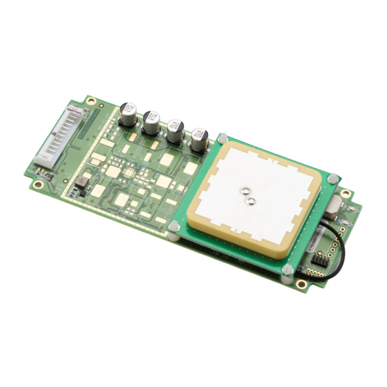
EL6e Development Kit Hardware
Included Components
The EL6e development kit contains:
•
1 x EL6e USB module
•
2 x Antennas (one for North America region range and one for EU region range)
•
1 x USB cable with 13-pin connector
•
1 x USB "Y" cable adapter
•
1 x Pack of sample RFID tags
•
4 x Antenna mounting hardware
•
4 x Stand-offs to protect the EL6e when used on a desktop or conductive surfaces
NOTE: Some of these parts cannot be ordered separately.
Set up the Development Kit
1. Select the antenna to use. When operating the EL6e Module, you will need to select a region of operation.
These regions will either be in the EU range (865 to 869 MHz) or the "NA" region (915 to 928 MHz). Using the
inappropriate antenna for your region setting results in poor performance and may shorten the life of the module
over time.
2. The EU antenna is marked 867M. The NA antenna is marked 924.5M. If the marking on the antennas are not
visible, they can be distinguished from one another by the appearance of the silver area, as shown below.
3. Carefully attach the U.FL connector on the antenna cable to the mating connector on the board. The cable
should be free to rotate around the connector without disconnecting.
NOTE: It is very difficult to re-seat this connector once the antenna is mounted on the board.
EL6E SMART MODULE
®
www.JADAKtech.com
Advertisement
Table of Contents

Related Manuals for Novanta JADAK THINGMAGIC EL6E


Summary of Contents for Novanta JADAK THINGMAGIC EL6E
- Page 1 ® GETTING STARTED WITH THE THINGMAGIC EL6E SMART MODULE EL6e Development Kit Hardware Included Components The EL6e development kit contains: • 1 x EL6e USB module • 2 x Antennas (one for North America region range and one for EU region range) •...
- Page 2 Getting Started - EL6 USB Dev Kit User Guide 4. Rotate the antenna and cable above the board until the RF cable is oriented as shown below. Any other orientation of antenna to the board will cause the components on the bottom of the antenna to interfere with those on the top of the board.
- Page 3 Getting Started - EL6 USB Dev Kit User Guide 9. The Assembled Development Kit should look like this: Communicate with the Development Kit The first step to enabling communication between the host PC and the EL6e board is to install the USB Driver (if necessary).
- Page 4 Getting Started - EL6 USB Dev Kit User Guide 7. Provide the .inf file path. 8. Proceed with the driver installation. Connecting the EL6e module 1. By default, the module behaves like an additional keyboard and “type” any tag information it sees. Before con- necting the module, either clear all tags away from the vicinity, or bring up an application to display tag data as it comes in, such as Windows Notepad.
Need help?
Do you have a question about the JADAK THINGMAGIC EL6E and is the answer not in the manual?
Questions and answers