Table of Contents
Advertisement
Quick Links
Advertisement
Table of Contents

Related Manuals for Fastus D4RF Series


Summary of Contents for Fastus D4RF Series
- Page 1 *FASTUS is a product brand of OPTEX FA. Digital Fiber Amplifier D4RF Series User’s Manual Before using this product, read this manual carefully. Keep this manual at hand so that it can be used whenever necessary. Store the manual in a secure location.
-
Page 3: Introduction
Thank you for purchasing this Digital Fiber Amplifier D4RF Series. This manual contains the information necessary for operating and configuring the D4RF Series. Read this manual thoroughly before using the product to ensure correct use with full understanding of its functions and performance. -
Page 4: Safety Precautions
Safety Precautions Safety precautions for ensuring safe operation of this product are displayed as follows with the following symbols. Precautions listed here describe important information about safety. Make sure to follow them accordingly. Safety Symbols „ The safety precaution symbols used and their meanings are listed below. Indicates that any improper operation or handling may result in moderate or minor injury, Warning and in rare cases, serious injury or death. - Page 5 Warning What to do in the event of a malfunction such as smoke being emitted from the product If you detect any malfunction including emission of smoke, abnormal smells or sounds, or the product enclosure becoming very hot, immediately stop operating the product and turn off the sensor power.
-
Page 6: Expressions Used In This Manual
NOTICE „ • After carefully considering the intended use, required specifications, and usage conditions, install and use the product within the specified ranges. • All specifications may be changed without notice. • When using this product, it is the responsibility of the customer to ensure necessary safety designs in hardware, software, and systems in order to prevent any threat to life, physical health, and property due to product malfunction or failure. -
Page 7: Manual Composition
Manual Composition This manual is composed of the following contents. This section explains the package contents of the D4RF (hereinafter 1. Read This First referred to as this product) and the names of its parts. 2. Installation and This section explains how to install and wire this product. Connection This section explains the necessary functions when using this product. -
Page 8: Table Of Contents
Contents Introduction .......................... i Safety Precautions ......................ii Expressions Used in This Manual ..................iv Manual Composition ......................v Read This First Package Contents ....................1-2 1-1-1 Options .................... 1-2 Part Names ......................1-3 1-2-1 Sensor Amplifier ................1-3 Display and Operation Section ............1-3 1-2-2 Installation and Connection Installation ...................... - Page 9 3-1-1 Screen Types .................. 3-2 Operations on the Setting Screen ........... 3-3 3-1-2 Setup on First Startup ..................3-4 Detection Method ....................3-5 Setting the Threshold (Teach Function) .............. 3-7 3-4-1 Threshold ..................3-7 3-4-2 Teach Mode ..................3-9 3-4-3 1 point ...................
- Page 10 [S1] Output mode (N.O./N.C.) ................4-5 [S3] Response time .................... 4-6 [S4] Timer ......................4-7 [S6] Display ......................4-9 4-5-1 [S6] - [P1] Display mode ..............4-9 4-5-2 [S6] - [P2] Hold display ..............4-11 4-5-3 [S6] - [P3] Brightness ..............4-11 4-5-4 [S6] - [P4] Rotate display ..............
- Page 11 4-7-7 [S8] - [O7] Load preset ..............4-28 [S9] Information ....................4-29 [SA] All devices ....................4-30 [SA] - [A1] Copy to all ..............4-30 4-9-1 [SA] - [A2] Zeroing all ..............4-30 4-9-2 [SA] - [A3] Zero reset all ..............4-31 4-9-3 4-9-4 [SA] - [A4] Set reset all ..............
-
Page 13: Read This First
Read This First This section explains the accessories and the names of this product’s parts. -
Page 14: Package Contents
1-1 Package Contents Before using this product, confirm that all of the following are contained in the package. If you find a defective or damaged item, contact OPTEX FA (with the information at the back of this userʼs manual). Fiber amplifier Mounting bracket Instruction manual 1-1-1 Options... -
Page 15: Part Names
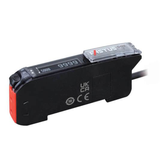
1-2 Part Names 1-2-1 Sensor Amplifier OLED display Interface cover Setting keys Lock lever Fiber insertion holes Cable models Connector Connector (Only on main unit models Cable length: 2 m, ø4.0 and expansion units) M8 4-pin plug connector 1-2-2 Display and Operation Section Name Description ①... - Page 16 Part Names...
-
Page 17: Installation And Connection
Installation and Connection This section explains how to install and wire this product. -
Page 18: Installation
2-1 Installation 2-1-1 Mounting the Fiber Unit ① Slide the lock lever down. ② Insert the fiber wires in the holes to the end. Check that the fibers are inserted correctly with the fiber insertion indicators. Fiber insertion indicators (White) When inserted correctly, the fiber insertion indicators will turn from white to black. -
Page 19: Attaching To/Removing From A Din-Rail
2-1-2 Attaching to/Removing from a DIN-rail Installing the Amplifier „ ① Place the groove on the side of the fiber unit holes on the DIN-rail. ② Press down until the hook locks. Removing the Amplifier „ ① Push the amplifier toward the side of the fiber unit holes. -
Page 20: Installing Inter-Connection Main/Expansion Units
2-1-4 Installing Inter-connection Main/Expansion Units 1. Mount each amplifier on the DIN-rail. 2. Slide the expansion unit and connect it to the inter-connection connector on the main unit. 3. Use the end plates on both sides to secure the amplifiers. Expansion unit Protective cover Main unit... -
Page 21: Wiring The Fiber Amplifier
2-2 Wiring the Fiber Amplifier CAUTION • Be sure to turn off the power before connecting/disconnecting connectors or wiring. • Cut lead wires that are not used, wrap them individually with insulating tape, and do not allow them to come into contact with other terminals. -
Page 22: I/O Circuit Diagrams In Io-Link Mode
2-2-1 I/O Circuit Diagrams in IO-Link Mode The circuit diagram by I/O model is shown below. 1-Output and 1-Switchable-Output/Input Models „ Brown ➀ Black ➃ White ➁ DI/DO Blue ➂ M8 connector pin layout 1-output + 1-input setting 2-output setting ➁... -
Page 23: I/O Circuit Diagrams In Sio Mode (Standard I/O Mode)
2-2-2 I/O Circuit Diagrams in SIO Mode (Standard I/O Mode) The circuit diagram by I/O model is shown below. 1-Output and 1-Switchable-Output/Input Models „ NPN setting Brown ➀ M8 connector pin layout 12 to 30 VDC (stand-alone unit) 1-output + 1-input setting 12 to 24 VDC ➁... - Page 24 2-Output and 1-Input Models „ NPN setting Brown 12 to 30 VDC (stand-alone unit) 12 to 24 VDC (inter-connection main unit) Load Black Control output 1 Load Gray Control output 2 White External input Blue *1: Power supply wires (Brown, Blue) are not equipped on the inter-connection expansion units. PNP or Push-pull setting Brown 12 to 30 VDC (stand-alone unit)
-
Page 25: Basic Usage
Basic Usage This section explains the types of display screens and transitions. -
Page 26: Display Screens
3-1 Display Screens This section explains the types of display screens and transitions. 3-1-1 Screen Types There are three types of screens: RUN, Teach, and Settings. ● RUN screen ● Teach screen 1 point TEACH TEACH Threshold and received light amount Teach mode selection ●... -
Page 27: Operations On The Setting Screen
3-1-2 Operations on the Setting Screen This section explains operations on the setting screen. Operation Keys „ The following keys are used when configuring settings. MENU TEACH Executes teaching escapes, Change settings. and returns to the higher menu (+: forward, −: backward) level. -
Page 28: Setup On First Startup
3-2 Setup on First Startup The first time you turn the product on or reset it, the following initial settings menu appears. Configure the settings in the order they appear. English MENU TEACH Select the language. English Press to select the language, and then MENU TEACH press... -
Page 29: Detection Method
3-3 Detection Method The main detection methods available are through-beam and diffuse reflective, which detect the object as shown below. Through-beam „ Two fiber units are installed so that one emits and one receives light, and the object passes between the units. - Page 30 Detection Method Features „ The features of the different detection methods are shown below. ◎: Excellent ○: Normal △: Poor Features Long Type General description Detection Installation range stability workload detection ◎ ◎ △ Through- With this type, detection is performed by installing two fiber beam units so that one emits and one receives light.
-
Page 31: Setting The Threshold (Teach Function)
3-4 Setting the Threshold (Teach Function) Set judgment criteria used by this product to judge whether an object is present. 3-4-1 Threshold Set according to the received light amount, the threshold is the standard value used to judge whether an object is present. - Page 32 Example) Received light amount and threshold of a diffuse reflective fiber unit When the light hits an object, light is reflected, increasing the received light amount. This level exceeding the threshold is judged to indicate the presence of an object. No object present Object present No object present...
-
Page 33: Teach Mode
3-4-2 Teach Mode The teach function, which requires the threshold to be set, has the following modes (types). Select the optimal mode for the fiber unit and the type of object to detect. ○: Effective ×: Not effective Detection method Sample Through- Teach mode... -
Page 34: Point
3-4-3 1 point The teach function is executed with no object present. The threshold is set to a value that does not detect the background. The threshold can be set easily with a single teach operation. Setup for 1-point teach [Diffuse reflective] Background Through-beam/... - Page 35 Output 1 With no object present, hold down for 1 indicator TEACH second or more. The output indicator of the channel (output 1 or output 2) for which the teach function is being Output 2 executed blinks once in orange. indicator Execute the teach function with the background.
- Page 36 Mechanism of the Threshold Setting „ The threshold is set to the value obtained by adding the specified percentage to the received light amount during execution of the teach function (with no object present). Example) When the received light amount during execution of the teach function is 100 and the detection margin is 10% If the received light amount when no object is present (the level for the background) is 100, the threshold is set to 110.
-
Page 37: Points
3-4-4 2 points In this mode, the teach function is executed at two points: with an object present and without an object present. The threshold is set to the median of the received light amounts for the first and second points, enabling the most stable detection. - Page 38 [Diffuse reflective] [Through-beam] With an object present, hold down for 1 TEACH Output 1 second or more. indicator The output indicator of the channel (output 1 or output 2) for which the teach function is being executed blinks in orange. Output 2 * Steps 3 and 5 can be performed in any order.
- Page 39 Mechanism of the Threshold Setting „ The threshold is set to the value in the middle of the received light amounts of the first and second points. Example) Diffuse reflective fiber unit Executing the teach function with an object present and without an object present results in the following results, the threshold is set to the median value, 600.
-
Page 40: Auto
3-4-5 Auto The threshold is set by executing the teach function with moving objects. This threshold can be set with the optimal sensitivity when the objects are small, making it difficult for them to block the light or when it is not possible to stop the production operations. Setup for Auto teach [Diffuse reflective] [Through-beam]... - Page 41 After a certain amount of time has passed 1400 Stop (less than 30 seconds), hold down for 1 MENU TEACH TEACH second or more. This completes the measurement of the received light amount. * If approximately 30 seconds elapse with TEACH being held down, the teach function will be canceled, and the threshold will not be set.
- Page 42 Mechanism of the Threshold Setting „ The peak and bottom amounts of received light monitored during auto teach are extracted, and the threshold is set to the median value. Example) Through-beam fiber unit If the highest amount of received light is 1000 and the lowest is 500, the threshold is set to the median value, 750.
-
Page 43: Through
3-4-6 Through The threshold is set to the lowest value required for detection on the basis of the received light amount when no object is present. This teach function is suitable for detection of targets such as small or transparent objects such as glass and film when using a through-beam/retro-reflective fiber unit. - Page 44 Press to set the teach mode and the Mode selected MENU detection margin. MENU TEACH The OLED display returns to the RUN screen and the received light amount appears. 1000 MENU TEACH With no object present, hold down for 1 Output 1 indicator TEACH...
-
Page 45: 1-Point Zone
Mechanism of the Threshold Setting „ The threshold is set to the value obtained by subtracting the specified percentage from the received light amount during execution of the teach function (with no object present). Setting the percentage used as a margin to the threshold to a smaller value allows for detection of highly transparent objects and small objects. - Page 46 Press for less than 1 second. TEACH The teach mode selection screen appears. to display “1-point Zone”, and 1-point Zone then press MENU TEACH MENU to adjust the detection margin to set the thresholds. MENU TEACH Use the percentage related to the received light amount during execution of the teach function to set the upper and lower limits that specify the threshold range.
- Page 47 The threshold is set and its display blinks. 1160 Refresh This completes the execution of the teach function. The OLED display automatically returns to the MENU TEACH RUN screen. Upper and lower thresholds * If the received light amount does not meet the conditions required for the teach function, “Teach To run mode error”...
-
Page 48: 2-Point Zone
3-4-8 2-point Zone The teach function is executed twice to set the upper and lower limits of the threshold. As with the “1-point Zone” teach mode, the threshold can be set to a fixed range of received light amount, so this method can be used to judge whether the object distance, position, and dimensions are within the set range. - Page 49 [Diffuse reflective] [Through-beam] With an object present, hold down for 1 Output 1 TEACH second or more. indicator The output indicator of the channel (output 1 or output 2) for which the teach function is being executed blinks once in orange. Output 2 * Steps 3 and 5 can be performed in any order.
- Page 50 Mechanism of the Threshold Setting „ The received light amounts obtained during the two actions of the teaching are set as the upper and lower thresholds. Example) When the received light amounts during the two actions of the teaching are 2000 and 1000 The threshold is set with an upper limit of 2000 and a lower limit of 1000, so detection occurs when the received light amount is in the range of 1000 to 2000.
-
Page 51: Manual Adjustment Of The Threshold
3-5 Manual Adjustment of the Threshold The threshold set with the teach function can be changed manually. Use this operation to make adjustments to the threshold when actual detection is unstable, when the detection conditions change, and other similar situations. This operation can also be used to set the threshold directly without executing the teach function. - Page 52 Operation Procedure „ (1-point Zone and 2-point Zone modes) On the RUN screen, press 1900 1000 A line appears at the bottom of the OLED display, 2000 MENU TEACH and the threshold blinks. Press to change the upper row 1700 1900 2000 threshold.
-
Page 53: Shortcut Function
3-6 Shortcut Function The shortcut function makes it possible to immediately call the useful functions explained in the following four display modes with one or two key operations. • Received Light Amount Display Modes • Switching to the Hold Display •... -
Page 54: Switching To The Hold Display
3-6-2 Switching to the Hold Display You can switch the display of the received light amount from the present value display to the hold display (where the peak and bottom received light amounts are displayed). Multiple hold display modes are available. ... -
Page 55: Lock Function
3-6-3 Lock Function This function locks the operations of this product to prevent incorrect operations. You can select to lock only key operations or key and external input operations. Operation Procedure „ Locking Simultaneously hold down for 1 second or more. Lock Operations are locked. - Page 56 Press , and then use to select the MENU Lock all required mode. MENU TEACH Lock keys MENU TEACH Press Lock mode MENU The setting is saved, and the OLED display returns MENU TEACH to the sub menu. Press TEACH The OLED display returns to the main menu.
-
Page 57: Switching The Display Between Output 1 And 2
3-6-4 Switching the Display between Output 1 and 2 This function switches the display between output 1 (channel 1) and output 2 (channel 2). Doing so allows you to configure settings for output 1 and 2 separately. Operation Procedure „ Hold down for 1 second or more. -
Page 58: Frequently Used Functions
3-7 Frequently Used Functions This section explains functions that are frequently used with this product. General description Function name Details Description Changing the output [S1] Output mode Select the output mode from light on (on when light is Page 3-35 mode received) and dark on (on when light is not received). - Page 59 3-7-1 [S1] Output Mode (N.O./N.C.) Set the output mode to light on (on when light is received) or dark on (on when light is not received). Switching the output mode inverts the output. Output mode Light on: Output generated when light is Dark on: Output generated when light is not Detection received.
- Page 60 Selectable Options with 1-point Zone and 2-point Zone Teach „ Modes, and Edge Height Threshold Mode With these setting options, the display becomes “N.O.” (normally open) or “N.C.” (normally closed), which causes output to be generated according to the following conditions pertaining to the threshold. Selectable option Function description N.O.
- Page 61 Press , and then use to select the Light on MENU required mode. MENU TEACH Dark on MENU TEACH N.O. * When the teach function is set to “1-point Zone” or MENU TEACH “2-point Zone”, “N.O.” or “N.C.” is displayed. N.C.
- Page 62 Example) Relationship between receiving/non-receiving light status and output timing Light received Receiving/non-receiving Light not light status received Output status (with the Light on setting) Response time Response time Selectable Options „ Selectable option Function description 16 µs (22 µs The response time can be selected from seven parameters. 70 µs 250 µs (default value) 500 µs...
- Page 63 Press Response time MENU The setting is saved, and the OLED display returns MENU TEACH to the main menu. Press To run mode TEACH This completes the settings. MENU TEACH The OLED display returns to the RUN screen. 3900 MENU TEACH RUN screen Response Time Setting Examples...
- Page 64 Number of Connectable Units with Cross Talk Prevention „ Affected by Response Time Setting When the inter-connection main unit and expansion units are connected, the cross talk prevention function activates to prevent errors due to light from adjacent fiber units. The number of main and expansion units that can be connected while still preventing cross talk varies depending on the response time setting, so refer to the following table to set the response time.
- Page 65 Operation Procedure „ * To cancel the setting, press the key. TEACH Press , and then use to select the MENU Display menu. MENU TEACH Display “Display” on the main menu. Press , and then use to select the Hold display MENU menu.
- Page 66 Mechanisms of Hold Display „ This section explains the display mechanism for each type of hold display. MEMO • The peak and bottom levels displayed with the hold display are numeric values resulting from sampling over a period of time. Therefore, there is a minor time lag compared to the present received light amount and output status. •...
- Page 67 Peak or Bottom These modes display either the peak value from times when the received light amount exceeds the threshold or the bottom value from times when the received light amount drops below the threshold. The peak or bottom level is updated each time the received light amount exceeds or drops below the threshold, respectively.
- Page 68 MEMO The “Peak” or “Bottom” hold display is useful for detection of small objects, for which the detection time is short, and thus it is difficult to monitor detection values. As only the “Peak” or “Bottom” is displayed, it is easy to read only the required values. Received light Peak level amount...
- Page 69 3-7-4 [P9] Stretch Mode This mode displays the received light amount multiplied by the set factor. No multiplication (difference x 10 (difference between threshold x 50 (difference between threshold between threshold and received and received light amount: 100) and received light amount: 500) light amount: 10) 4500 1000...
- Page 70 Press , and then use to select the On - x10 MENU option to set. MENU TEACH <Options> Off, On - x10, On - x50 Press MENU Stretch mode The setting is saved, and the OLED display returns MENU TEACH to the main menu.
- Page 71 3-7-5 [S7] - [D2] Threshold Mode “Edge height” Threshold mode of “Edge height” generates outputs when there are sudden changes in the received light amount. The operating principle is differentiation detection. The received light amount is monitored for the cycle set with “Response time”...
- Page 72 Setup Flow „ For the Edge height setting, configure the basic settings with “[S7] - [D2] Threshold mode”, and then execute the teach function. Then, configure the setting parameters related to Edge height as necessary. Settings Basic settings Threshold mode Edge direction [S7] - [D2] (page 4-16) Edge offset...
- Page 73 Edge Direction ([S7] - [D2], [S7] - [D8]) „ Select a direction of detection with Edge height. Selectable option Function description Both (default value) Output is generated when the received light amount increases or decreases. Negative Output is generated when the received light amount decreases. Positive Output is generated when the received light amount increases.
- Page 74 Edge Offset ([S7] - [D2], [S7] - [D9]) „ Edge offset sets the length of time to compare for changes to the received light amount. Set it as follows together with “Response time”. • Edge offset: Sets the length of time to compare the present received light amount and the monitored received light amount.
- Page 75 Setting Description The Edge offset that can be set varies depending on the “[S3] Response time” setting. Before setting Edge offset, set “[S3] Response time” appropriately. Selectable option Function description 16 µs to 4080 µs (default value: 160 µs) Selectable when “Response time” is set to 16 µs 22 µs to 5610 µs (default value: 220 µs) Selectable when “Response time”...
- Page 76 Teach for Edge height ( „ TEACH When setting Edge height mode, execute the teach function with no object present. When the teach function is executed, the amount of change (difference) in the received light amount with the background is set as the threshold. •...
- Page 77 Edge Peak Display ([S9] - [IB]) „ This displays the the largest, smallest, and present differences between the received light amounts of the measured and set comparison targets. This function is useful when checking whether objects are detected appropriately with the Edge height setting.
- Page 78 Operation Procedure 1 (Setting Threshold mode to Edge height) „ Press , and then use to select the MENU S7 Detection menu. MENU TEACH Display “Detection” on the main menu. Press , and then use to select the MENU D2 Threshold mode menu.
- Page 79 Hold down for 3 seconds or more. To run mode TEACH The OLED display returns to the RUN screen. MENU TEACH The screen switches to the Edge display. The displayed numeric value is the difference in the received light amounts. The sign for the Edge ±100 direction(s) are indicated in front of the threshold MENU...
- Page 80 After a certain amount of time has passed Stop (less than 30 seconds), hold down for 1 MENU TEACH TEACH second or more. This completes the measurement of the received light amount. * If approximately 30 seconds elapse with TEACH being held down, the teach function will be canceled, and the threshold will not be set.
- Page 81 3-7-6 [SC] Reset Resets the settings of this product. Selectable Options „ You can select from the following reset modes. Selectable option Function description Setting reset Returns the settings of this product to the factory defaults. The preset data in which product settings have been registered are excluded.
- Page 82 3-58...
- Page 83 Settings Menu This section explains how to set the parameters of this product.
- Page 84 4-1 List of Setting Options A list of the options that can be set on this product is shown below. The initial settings are indicated with underlining. Output mode (N.O./N.C.) Page 4-5 Page 4-12 Alarm display Light on, Dark on, (N.O./ N.C.) Off, On Page 4-6 Response time...
- Page 85 Detection Page 4-15 Page 4-26 Pin 5 setting* Page 4-19 Counter Output 2, Alarm output, Input ack., Not used Off, On *: Displayed on 2-output and 1-input models. Page 4-21 Set count* Page 4-26 Pin 2 setting 1 to 16383 (10) *: Displayed when “On”...
- Page 86 Page 4-30 All devices* *: Displayed on inter-connection main unit. Page 4-30 Copy to all No, Copy to all Page 4-30 Zeroing all No, Zeroing all Page 4-31 Zero reset all No, Zero reset all Page 4-31 Set reset all No, Set reset all Page 4-31 Fct.
-
Page 87: S1] Output Mode (N.o./N.c.)
4-2 [S1] Output mode (N.O./N.C.) Selects the control output mode from light on (on when light is received) and dark on (on when light is not received). For details on this function and how to set it, refer to “3-7-1 [S1] Output Mode (N.O./N.C.)”... -
Page 88: S3] Response Time
4-3 [S3] Response time Selects the response time of this product. For details on this function and how to set it, refer to “3-7-2 [S3] Response Time” (page 3-37). [S3] Response time... - Page 89 4-4 [S4] Timer This function delays the control output of this product. Selectable Options „ You can select the timer setting from the following six timer modes. Selectable option Function description Setting value Not used Do not use the timer function. (Default value) —...
- Page 90 <Off delay operation> The output is turned off at the set timer time after the detection becomes off. Therefore, even if the detection becomes OFF momentarily, as indicated by B, the output does not turn off. This prevents chattering. Furthermore, setting an Off delay can lengthen the output time in cases where the objects are small and the sensor only turns on for brief periods of time.
- Page 91 4-5 [S6] Display This section explains how to set the display modes and received light amounts on the OLED display. 4-5-1 [S6] - [P1] Display mode Sets how to show the received light amount on the OLED display. Selectable Options „...
- Page 92 Example) After executing the teach function with the 1-point Zone or 2-point Zone setting The thresholds for the upper and lower limits are displayed. 110% 100% Thresholds Received light amount Bar graph „ Displays the received light amount on a bar graph. One or more thresholds are also displayed on the bar graph.
-
Page 93: P2] Hold Display
4-5-2 [S6] - [P2] Hold display Continuously displays the highest value (peak level) and lowest value (bottom level) among all the times the received light amount exceeds the threshold and drops below the threshold. For details on the Hold display function and how to set it, refer to “3-7-3 [P2] Hold Display”... -
Page 94: S6] - [P5] Invert Display
4-5-5 [S6] - [P5] Invert display You can invert the colors of the text and background on the OLED display. Selectable option Function description Off (default value) This is the standard display with white characters on a black background. Inverts the colors of the text and background. The text becomes black and the background white. -
Page 95: P9] Stretch Mode
4-5-7 [S6] - [P7] Zeroing Executing the Zeroing function sets the current received light amount as zero. Use this function when, for example, you want to set the reference received light amount as zero or you want to set no object present as zero but the actual received light amount is not zero. Selectable option Function description Not used (default value) -
Page 96: S6] - [Pa] Language
4-5-10 [S6] - [PA] Language Sets the language of the menu text on the OLED display. Selectable Options „ You can select from the following five languages. Selectable option Function description English (default value) The text is displayed in English. 日本語... -
Page 97: S7] Detection
4-6 [S7] Detection This function is used to configure advanced settings related to detection, such as making adjustments to the reference for detection judgment, the output timing, the emitter power, and the sensitivity. 4-6-1 [S7] - [D1] Hysteresis This function adjusts the received light amounts to turn the output on and off (it configures the margin between these levels). -
Page 98: S7] - [D2] Threshold Mode "Edge Height
ON at the operation point OFF at the reset point Received light amount Operation point (threshold) (Hysteresis set to 5%) Reset point (Hysteresis set to 20%) Time Output is repeatedly turned ON/OFF. When Hysteresis is set to 5% Remains ON until the received light amount falls below the set Hysteresis of When Hysteresis is... -
Page 99: S7] - [D3] Apc
4-6-3 [S7] - [D3] APC This function automatically adjusts the power input to the emitter LED. When the emitter power becomes unstable due to the ambient temperature or aging deterioration of the LED, this function stabilizes detection by maintaining the emitter power. MEMO •... -
Page 100: S7] - [D5] Emitter Power
Adjustment Example „ The threshold is automatically adjusted when the received light amount decreases due to contamination, temperature changes, etc. Present received light amount Received light amount Reference received light amount Threshold Time The received light amount The received light amount recovers decreases due to contamination, when some measure is taken, such temperature changes, etc. -
Page 101: S7] - [D6] Counter
Selectable Options „ Selectable option Function description Max (default value) The emitter power can be selected from three options. The received light amount with the selected emitter power is displayed on the right of the screen. Auto The emitter power is automatically adjusted to prevent saturation upon teaching. 4-6-6 [S7] - [D6] Counter This mode counts the number of times that objects are detected, and generates output when the target count specified with “[S7] - [D7] Set count”... - Page 102 Selectable Options „ Selectable option Function description Off (default value) Counter mode is not used. Enables Counter mode. Set count is set to 10 as default. It can be set to a value in the range of 1 to 16383. Operation Procedures „...
-
Page 103: S7] - [D7] Set Count
Press To run mode TEACH This completes the settings. MENU TEACH The OLED display returns to the RUN screen. MENU TEACH Set count Counter Related Setting „ You can change the Set count ([S7] - [D7]). In Counter mode, this setting indicates how many objects must be detected (counter) to generate output. This setting parameter is only displayed when Counter ([S7] - [D6]) is enabled. -
Page 104: S7] - [D9] Edge Offset
Selectable Options „ Selectable option Function description Positive Output is generated when the received light amount increases. Negative Output is generated when the received light amount decreases. Both (default value) Output is generated when the received light amount increases or decreases. 4-6-9 [S7] - [D9] Edge offset This menu sets the interval in which to compare difference in the received light amounts with Edge mode. - Page 105 Adjust the value of Edge hys. for a range of received light amount below the operation difference to hold the output on. For example, if you want to reduce the detection fluctuation caused by vibration, set a larger Edge hys., and if you want to detect small objects, set a smaller Edge hys.
-
Page 106: S8] I/O
4-7 [S8] I/O This function configures the settings of external input/output, such as I/O polarity, external input mode, lock mode, read/write of presets, etc. 4-7-1 [S8] - [O1] I/O polarity This menu sets the I/O polarity of this product. Selectable Options „... -
Page 107: S8] - [O2] Pin 2 Setting
4-7-2 [S8] - [O2] Pin 2 setting This assigns the (I/O) function of the white wire. For the setting of pin 2 on analog output types, refer to “4-7-4 [S8] - [O4] Pin 2 setting” (page 4-26). Selectable Options „... -
Page 108: S8] - [O3] Pin 5 Setting
4-7-3 [S8] - [O3] Pin 5 setting This assigns the (output) function of the gray wire. This setting is applicable to 2-output models, D4RF-TD*. Selectable Options „ Selectable option Function description Output 2 (default value) Sets as control output 2. Alarm output The received light amount set for output 1 is monitored in the range of 0 to 254%. -
Page 109: S8] - [O5] Lock Mode
4-7-5 [S8] - [O5] Lock mode This sets the target settings of this product to be locked. For details on the Lock function, refer to “3-6-3 Lock Function” (page 3-31). 4-7-6 [S8] - [O6] Preset setting You can register (save) up to five sets of parameters on this product. Preregistered setting parameters of different operations can be loaded according to operation changes. -
Page 110: S8] - [O7] Load Preset
4-7-7 [S8] - [O7] Load preset Loads settings (Preset 1 to Preset 5) saved with [O6] Preset setting. CAUTION Note that executing the Load preset function overwrites the present settings, which cannot be recovered. MEMO When this product is shipped from the factory, the factory defaults are registered to the settings in Preset 1 to Preset 5. Before using this function, use [S8] - [O6] Preset setting to register settings. -
Page 111: S9] Information
4-8 [S9] Information This displays the information of this product. Selectable option Function description [S9] - [I1] Serial number Displays manufactured time. [S9] - [I2] Firmware ver. Displays firmware version. [S9] - [I3] Hardware ver. Displays hardware version. [S9] - [I4] Temperature Displays internal temperature of this product in Celsius. -
Page 112: Sa] All Devices
4-9 [SA] All devices Various operations can be performed on the connected main units and expansion units. This setting menu is displayed when an expansion unit is connected to the inter-connection main unit. 4-9-1 [SA] - [A1] Copy to all This copies the settings of the main unit to all the connected expansion units. -
Page 113: Sa] - [A3] Zero Reset All
4-9-3 [SA] - [A3] Zero reset all This cancels the Zeroing all function ([SA] - [A2]) executed on all connected expansion units. 4-9-4 [SA] - [A4] Set reset all This initializes all connected expansion units, except for the preset data. 4-9-5 [SA] - [A5] Fct. -
Page 114: Sc] Reset
4-10 [SC] Reset This initializes the settings of this product to the factory defaults. For details on this function and how to set it, refer to “3-7-6 [SC] Reset” (page 3-57). [SC] Reset 4-32... -
Page 115: Troubleshooting
Troubleshooting This section describes error displays and countermeasures for errors that occur during product use. -
Page 116: Error Displays
5-1 Error Displays This section provides countermeasures for errors displayed during the execution of the teach function. Error display Cause Countermeasure Teach error 1 While executing the teach function, the received To increase the received light amount, carry out (Output indicator light amount is too small to set the threshold. - Page 117 Error display Cause Countermeasure While executing the teach function of the 2-point Increase or decrease the distance to the object Teach error 4 (Output indicator Zone the difference between the received light when setting one of the thresholds. (When using blinks in amount from the first and second teach a diffuse reflective fiber unit.)
-
Page 118: Errors And Countermeasures
5-2 Errors and Countermeasures This section provides countermeasures for errors that occur during product use. Error Cause Countermeasure Power indicator (green) does not The supply voltage is insufficient Check whether the provided indicator illuminate. or unstable. supply voltage is stable. Power indicator blinks in green. - Page 119 Error Cause Countermeasure Light from an adjacent fiber unit is • When an inter-connection main Detection Detection is made (the output indicator illuminates in orange) received. unit and expansion units are even though no object is present. connected, cross talk prevention eliminates interference between the units.
- Page 120 Error Cause Countermeasure The hysteresis value is too small The hysteresis value is too small Detection Detection is not made (the output indicator [orange] turns off) even to maintain on output. to maintain on output. (page though an object is present. 4-15) When the timer function is not in The change in the light reflected...
- Page 121 Error Cause Countermeasure The received light amount is • The emitter or receiver surfaces • Clean the dirt without damaging Received light insufficient. of fiber unit gets dirty. the tip. amount • Review the distance and • The sensing distance (through- beam: distance between the environment of installation and emitter and receiver of fiber unit,...
- Page 122 Errors and Countermeasures...
-
Page 123: Appendix
Appendix This section contains information such as the specifications, IO-Link index list, and factory default settings. -
Page 124: Specifications
6-1 Specifications 6-1-1 Sensor Amplifier Specifications Stand-alone unit Inter-connection Type Inter-connection main unit (IO-Link device) expansion unit Model 1 output and Cable type D4RF-T D4RF-TM D4RF-TS 1 switchable Connector D4RF-TC4 D4RF-TMC4 D4RF-TSC4 output/input type 2 outputs and Cable type D4RF-TD D4RF-TDM D4RF-TDS 1 input... - Page 125 Stand-alone unit Inter-connection Type Inter-connection main unit (IO-Link device) expansion unit Rating Supply SIO mode 12 to 30 VDC ± 10% including 12 to 24 VDC ± 10% including Supplied from main unit voltage 10% ripple (p-p) 10% ripple (p-p) (12 to 24 VDC ±...
-
Page 126: Dimensions
6-1-2 Dimensions Stand-alone Unit „ Connector model (D4RF-TC4) Unit: mm 79.15 Open angle approx. 135° and 180° M8, 4-pin plug connector 2 × ø2.3 10.5 18.8 36.6 74.25 Cable models (D4RF-T, D4RF-TD) Cable length: 2 m ø4.0 5 wires, 4 wires × 0.18 mm² Specifications... - Page 127 Inter-connection Unit „ Connector models (D4RF-TMC4, D4RF-TSC4) 51.9 Unit: mm 51.9 Expansion unit only 79.15 Open angle approx. 135° and 180° M8, 4-pin plug connector 2 × ø2.3 10.5 18.8 36.6 74.25 Cable models (D4RF-TM, D4RF-TDM, D4RF-TS, D4RF-TDS) Cable length: 2 m ø4.0 5 wires, 4 wires, 3 wires, 2 wires ×...
- Page 128 Straight Connector Cable (M84CN-2S, M84CN-5S, M84CN-10S; „ Optional) Unit: mm L = 2000 (M84CN-2S) = 5000 (M84CN-5S) = 10000 (M84CN-10S) ø4.8 M8 × 1 ø10 Cable material: PVC, conductor cross-section: 4-wire × 0.25 mm End Plate (BEF-EB01-W190; Optional) „ 43.5 10.5 M4 ×...
-
Page 129: Index List
HEX: 10009 6-2-2 Process Data Format With the D4RF series, the content of process input data transmitted via IO-Link communication can be selected from the following two formats. • The format of process input data can be switched by using Index 120. -
Page 130: Service Data
6-2-3 Service Data Length Index No. Read/ Category Name index Backup Format Default Setting details Remarks (Unit) DEC (HEX) Write bytes System System command 2 (0x02) UINT 0x41: 1-point teach (threshold 1) 0x42: 1-point teach (threshold 2) 0x43: 2-point teach (teach point 1) 0x44: 2-point teach (teach point 2) 0x45: Through teach 0x47: Auto teach start... - Page 131 Length Index No. Read/ Category Name index Backup Format Default Setting details Remarks (Unit) DEC (HEX) Write bytes Detection Teach status 59 (0x3B) UINT Bit 0 to 3: Teach status Setting 0: IDLE 1: 1-PT SUCCESS 2: 2-PT SUCCESS 3: 1/2-PT SUCCESS 4: WAITING FOR COMMAND 5: BUSY 7: ERROR...
- Page 132 Length Index No. Read/ Category Name index Backup Format Default Setting details Remarks (Unit) DEC (HEX) Write bytes ✓ Detection Response time 95 (0x5F) UINT 0x00: 8000 µs Settings 0x01: 2000 µs 0x02: 1000 µs 0x03: 500 µs 0x04: 250 µs 0x05: 70 µs 0x06: 16 µs General...
- Page 133 Length Index No. Read/ Category Name index Backup Format Default Setting details Remarks (Unit) DEC (HEX) Write bytes Diagnosis Operating hours: Total 190 (0xBE) UINT operating hours Operating hours: UINT Operating hours since last reset Identification Find me 204 (0xCC) UINT 0x00: Find me deactivated 0x01: Find me activated...
- Page 134 Length Index No. Read/ Category Name index Backup Format Default Setting details Remarks (Unit) DEC (HEX) Write bytes ✓ Smart task Input selector 2 1082 UINT 0x00: Qint. 1 (0x43A) 0x01: Qint. 2 0x40: Ext. input 1 ✓ Logic 1 1083 UINT 0x00: DIRECT...
-
Page 135: Events
6-2-4 Events Code Description 4227 0x1083 Received light amount diagnostic 6144 0x1800 High temperature (depends on high temperature setting of index 179, subindex 1) 6145 0x1801 Low temperature (depends on low temperature setting of index 179, subindex 2) 6146 0x1802 Operating hours (depends on Operating hours setting of index 179, subindex 3) 30480 0x7710... -
Page 136: Initial Settings List
6-3 Initial Settings List This section describes the factory default settings of this product. When this product is reset ([SC] Reset - [SB] Factory reset/Setting reset), the settings return to the parameters listed below. Main menu Sub menu Default value Description Output mode (N.O./ N.C.) —... - Page 138 Attention: Not to be Used for Personnel Protection. Never use these products as sensing devices for personnel protection. Doing so could lead to serious injury or death. These sensors do not include the self-checking redundant circuitry necessary to allow their use in personnel safety applications. A sensor failure or malfunction can cause either an energized or de-energized sensor output condition.
Need help?
Do you have a question about the D4RF Series and is the answer not in the manual?
Questions and answers