
Summary of Contents for Global IFS FDU-1-1
- Page 1 Global IFS Fan Powered Box Tool Check List Installation Instruction Fan Powered Box & Terminal Unit (FPB & TU) Global IFS Fan Powered Box Page: 1 of 9...
- Page 2 FAN POWERED BOX & TERMINAL UNIT Control Assembly Label All Global IFS fan powered terminal units are tagged with a control assembly label as shown on the left. This label identifies the model number, location tag #, controller type, actuator type, thermostat action, application and controller setpoints.
-
Page 3: Installation Overview
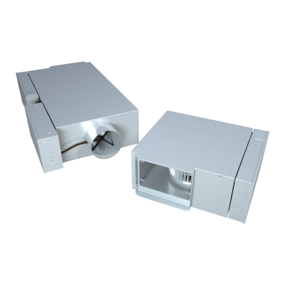
Instructions Mounting The Unit Global IFS Fan Powered Terminal Units are designed to be mounted in the direction indicated by the Control Assembly Label found on the protective shroud. Mount the unit directly on the sub-floor, beneath the raised floor. Ensure the area where the unit is to go is clear of cables, wires, etc. -
Page 4: Start-Up And Operation
12. Set the thermostat to full heating. The fan should be on and the primary air valve (if present) at minimum flow. Verify the primary air volume with sensor taps or pitot tube traverse. Adjust if necessary. 13. Always set the fan volume at full cooling. Global IFS Fan Powered Box Page: 4 of 9... - Page 5 Standard ECM Speed Controller The Global IFS standard speed controller allows manual adjustment of the fan flow using the adjustment dial on the control board and a voltmeter. Remote control of the fan speed is also possible with the BAS input. The following chart describes the controller response to a 0-10 VDC input.
- Page 6 ECM Deluxe Speed Controller Adjustment ECM DELUXE SPEED CONTROLLER The Global IFS Deluxe ECM speed controller works with a high efficiency ECM motor. This low voltage (24 VAC) speed control allows full manual (push button adjust) or BAS (2-10 VDC signal) control of the ECM motor.
-
Page 7: Maintenance
Check the disconnect switch or breaker. The supply voltage must be identical to the wiring diagram. e. Ensure the fan wheel is not touching the blower casing. Global IFS Fan Powered Box Page: 7 of 9... -
Page 8: Typical Wiring Diagram
This could cause a significant power spike if many units are turned on at once. For reference only. For actual wiring specific to the supplied units please refer to the wiring diagram supplied with each unit. Global IFS Fan Powered Box Page: 8 of 9... -
Page 9: Replacement Parts
Discharge Attenuator Part# Reference (506271-XXX) Unit Size Configuration STD BOX/EC STD BOX/EC STD BOX/EC STD BOX/EC STD BOX/EC/WC BOX W/ CWC 10/20 BOX W/ HWC(10), CWC/HWC (20) BOX W/ WC BOX W/ WC Global IFS Fan Powered Box Page: 9 of 9...
Need help?
Do you have a question about the FDU-1-1 and is the answer not in the manual?
Questions and answers