
Summary of Contents for Fan Turbine WT6500
- Page 1 Fan Turbine FAN TURBI NE 5KW This manual is intended solely for use by a Licensed Contractor of Fan Turbine.
- Page 2 Turbine. Please read this Owner's Manual carefully and always use Fan Turbine Authorized Installers or other licensed contractors for proper installation. The Fan Turbine manufactured by Fan Turbine Inc., fanturbine1@gmail.com www.fanturbine.com. 1800-489-0908.
-
Page 3: Table Of Contents
Safety Instructions............1. Introduction Product Description ................2 Shipping Contents ................2 Before Installing the Fan Turbine ............. 3 Transportat ion and Storage ..............3 Preassembly..................4 Turbine Brake ..................4 2. Specifications Technical Specifications ................. 6 3. Turbine Installation... -
Page 4: Safety Instructions
TIP: HELPFUL INFORMATION TO EASE THE INSTALLATION Important Safety Instructions 1. This Owner's Manual contains important instructions for the Fan Turbine installation and maintenance Read entire Owner's Manual prior to installation follow warnings and cautions included in Owner's Manual and/or... - Page 5 Appropriate protective personal equipment such hard hat, work gloves, safety glasses, closed toe work shoes should be worn when installing Turbine. Only Fan Turbine Authorized Installers or other licensed contractors perform the installation and maintenance functions this Fan Turbine: installation directions...
-
Page 6: Introduction
Introduction For Information On: See: Product Description Shipping Contents Before Installing Transportation Storage Preassembly Turbine Brake... -
Page 7: Product Description
Shipping Contents 1. One (1) Fan Turbine generator with bracket, bearing, mount, and hub preassembled. (4) Carbon Blades (1) Slip Ring (24) M6 Bolts and (24) locknuts, (24) steel washers and (24) plastic wasters (1) 3 Phase bridge rectifier AC to DC... -
Page 9: Before Installing The Fan Turbine
Before Installing the Fan Turbine: IMPORTANT Please take note that Fan Turbine is a proprietary wind driven electric generator. designed to reduce annual electric consumption connecting it to the electric grid at the breaker panel. also be used as a stand-alone installation where... -
Page 10: Preassembly
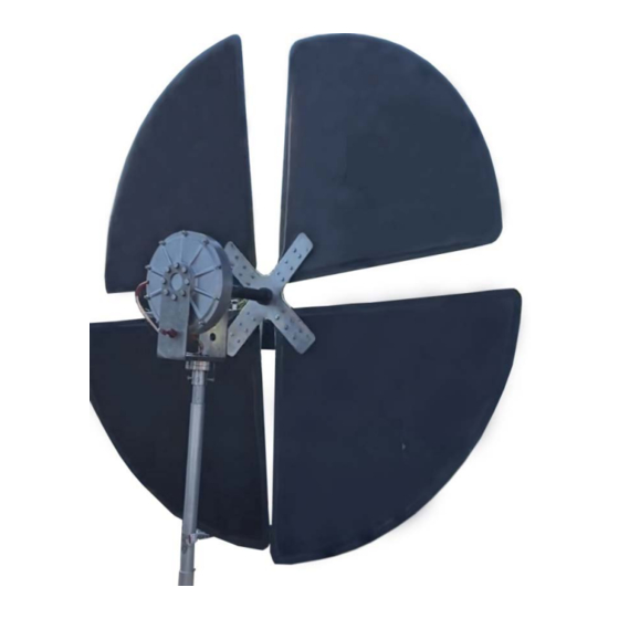
Preassembly Only Fan Turbine Authorized Installers or other licensed contractors can move lift the Fan Turbine assembly. components of the assembly are described in figure 1.2: Figure 1.2: Turbine Components Turbine Brake Only Fan Turbine Authorized Installers or other licensed... - Page 11 Generator shall be in brake position before and during the installation of the blades or generator and shall only be WARNING disconnected once all maintenance or installation is completed. Failure to do so may result in injury and/or property damage. maintenance is to be done turbine, the turbine...
-
Page 12: Specifications
Specifications For Information On: See: Technical Specifications... -
Page 13: Technical Specifications
Technical S p e c i f i c a t i o n s Model WT6500 Specification Rated Power Output 5000 KW at (13.9 m/s) Turbine: kg), Weight Rotor Diameter (1.82 Type Blade Power System™ 4 Carbon – Xenecore Blades... -
Page 14: Turbine Installation
Turbine Installation For Information on: See: Introduction Site Selection Turbine Spacing Mounting Options Rectifier Blades Assembly Wiring Grounding Operation... -
Page 15: Turbine Mounting
PERSONAL INJURY PROPERTY DAMAGE HAZARD Fan Turbine can only connected an Inverter approved Turbine. Failure follow this warning may void the WARNING Turbine warranty and may result personal injury or property damage (including damage to Fan Turbine). -
Page 16: Site Selection
Site Selection The key objective of a site evaluation or study to place Fan Turbine so energy generated from wind is maximized while meeting local zoning requirements. elements to focus on during the site evaluation include: High average wind speeds. -
Page 17: Assembly
ASSEMBLY: SLIP RING : The 3 wire slip ring allows the generator to turn 360 degrees maintaining the 3 wire AC output. The 20A slip ring is positioned between the Mount and the 1.5” pole. The lower wires of the slip ring should be connected to the down lead wire connected to the rectifier/inverter assembly and grid. - Page 18 THE ASSEMBLY COMES WITH M6 CAP BOLTS and NUTS. 1/4"-20 HEX BOLTS AND LOCK NUTS CAN ALSO BE USED. WHILE ONE PERSON IS HOLDING THE BACK OF THE NUT WITH A WRENCH OR M6 CAPS NUT WRENCH (M6 ALLEN WRENCH), THE OTHER PERSON IS SECURING 6 HOLES WITH A PLASTIC WASHER, METAL WASHER AND LOCKNUT.
- Page 19 EACH POSITION IS SECURED BY A PLASTIC WASHER AGAINST THE CARBON, THEN THE METAL WASHER, THEN THE LOCK NUT ON THE OUTSIDE. DO NOT OVERTIGHTEN THE LOCK NUTS WHICH COULD CRUSH THE CARBON BLADES. SAFETY HOLD. THIS INDICATES THE PROPER WAY TO GET CONTROL OF THE GENERATOR WHICH IS SPINNING.
-
Page 20: Rectifier
Rectifier : 3 phase Bridge Rectifier will convert the three phase AC output from the generator to DC. -
Page 21: Blades Assembly
BLADE Assembly PROFESSIONAL INSTALLATION: REQUIRED... - Page 22 Figure 2.7: Figure 2.8: Remove deflector from packaging. Ensure six (6) nuts fully tightened with plastic washer, metal washer, and lock nut Figure 2.9: Ensure the nuts are tight with plastic washers Figure 2.11: against the carbon. Mount the blades with brake on by touching two the generator wires together.
- Page 23 Mount blades one at a time 2 persons. Figure 2.12: Brake Repeat steps remaining blades Figure 2.10: Mount blades 2 persons one at a time with brake on Lock the assembly with 4 x M8 Bolts against the pole and lock in the poles to the mounting stand.
-
Page 24: Turbine Wiring
PERSONA INJURY AND PROPER TY DAMAG E HAZARD Connecting the Fan Turbine to any Inverter other than a Turbine approved Inverter void Fan Turbine warranty WARNING and may result in personal injury property damage (including damage to the Turbine). Installations must meet... -
Page 25: Operation
Please contact Fan Turbine Customer Service with any questions. noise or vibration is detected or the turbine's blades rotate very slowly under extremely windy conditions turn turbine off please contact Fan Turbine Customer Service. -
Page 26: Warranty Information
Warranty Information... - Page 27 Customer Service at 800-489-0908 and written notices shall sent Fan Turbine I n c . f a n t u r b i n e 1 @ g m a i l . c o m _ Attn.: Customer Service - Warranties Purchaser...
- Page 28 Purchaser. All replaced parts products shall become property of Fan Turbine on the date the part or product is replaced.
- Page 29 Turbine, damage caused severe weather acts of God, other act or event beyond control of Fan Turbine, i.e. lightning; product been exposed to winds exceeding (62.6 m/s) been subjected abnormal physical, thermal or electrical stress.
- Page 30 Changes to this Limited Warranty: Fan Turbine may change this warranty from time to time. When Fan Turbine makes changes warranty, it will post them www.FanTurbine .com. warranty that shall apply product...
-
Page 31: Ec Declaration Of Conformity
Directive IEC 60204-1 Safety of Machinery Electrical Equipment Directive Hereby declare that: Equipment Fan Turbine and Fan Turbine Wind Turbine Model numbers in conformity with the applicable requirements of the following documents: Ref. No. Title Edition/Date IEC 61 439-1 Low-Voltage... - Page 32 Fan Turbine Inc. Fan Turbine www.FanTurbine.com...
Need help?
Do you have a question about the WT6500 and is the answer not in the manual?
Questions and answers