Table of Contents
Advertisement
Quick Links
SIGH OFF/ON Pushbutton Switch: Default value is "OFF". When
set to "ON", first breath delivered is a SIGH, then once every 100-
breaths or 7-minutes thereafter (whichever occurs first). Each
SIGH equals 150% of Inspiration Time setting, delivered volume is
increased by 50%. Status displayed in LCD (beaneath Pushbutton
Switch).
ALARM MESSAGE CENTER (AMC): A
centralized location for displaying up to 4-lines
of alarm message information. Up to 2-alarms
with, short messages, may be displayed
simultaneously. If more than 2-alarms occur
simultaneously, only the name of each alarm is
displayed (as shown below in boldface).
BATTERY LOW/FAIL-RECHARGE/
REPLACE BATTERY PACK
EXTERNAL POWER LOW-CHECK
POWER SOURCE/CONNECTIONS
O2 LOW/FAIL-CHECK OXYGEN
SOURCE/CONNECTIONS
EXT AIR LOW/FAIL-CHECK AIR
SOURCE/CONNECTIONS
LOW PRESSURE-PEAK INSPIRATORY
PRESSURE TOO LOW
DISCONNECT-CHECK CIRCUIT
CONNECTIONS
HIGH PRESSURE-PEAK INSPIRATORY
PRESSURE TOO HIGH
APNEA-CHECK PATIENT FOR
SPONTANEOUS BREATHING
APNEA-CPAP AVERAGE RATE LESS
THAN 6-BPM
HIGH PEEP-INSPIRATION BEGAN
BEFORE END PRESSURE PLATEAU
FIO2-GAS MIX ERROR. CHECK
SOURCE/SETTINGS/CONNECTIONS
PRESSURE ALARM SETTINGS-ALARM
SETTINGS REVERSED
VT-DELIVERED TIDAL VOLUME DOES
NOT EQUAL SET TIDAL VOLUME
COMP-COMPRESSOR OUTPUT
LOW/FAIL
INSPIRATION TIME TRUNCATED
TO 3-SEC - NOTE I-TIME & I:E
PLATEAU VOLUME-DELIVERED
VOLUME LESS THAN SET VOLUME
VT SETTINGS - I-TIME X FLOW
UNABLE TO DELIVER SET VOLUME
EXT PWR FAIL/DISCONNECT - CHECK
POWER SOURCE/CONNECTIONS
TOTAL FLOW BACKUP -
CONTACT CUSTOMER SERVICE
INVERSE I:E-INSPIRATORY TIME
LONGER THAN EXHALATION TIME
TRANSDUCER CALIBRATION ABORT
RECALIBRATE TRANSDUCER
The following alarm overrides any of the above
messages when activated:
VENTILATOR FAILURE DETECTED
* this alarm is followed by one of the following *
FAILURE CODE 1
SELF-CHECK FAILURE!
FAILURE CODE 2
NO GAS AND COMPRESSOR FAILURE!
FAILURE CODE 3
EXCESSIVE AIRWAY PRESSURE!
FAILURE CODE 4
MEMORY CHECK FAILURE!
FAILURE CODE 5
EXHALATION VALVE FAILURE!
FAILURE CODE 6
EXCESSIVE NEGATIVE PRESSURE!
FAILURE CODE 7
RUN-TIME CALIBRATION FAILURE!
PEEP OFF/ON-SET Pushbutton Switch:
Sets internally-generated PEEP setpoint.
Default value is "OFF". Range is from 0 to
20 cmH O. Value increases by 1, each
2
time pushbutton is pressed. Value displayed
in LCD (beneath Pushbutton Switch).
EXTERNAL AIR OFF/ON
Pushbutton Switch: Use with
nominal 50-PSI compressed gas
source. Default value is "OFF".
Status displayed in LCD (beneath
Pushbutton Switch).
MODE Indicator: Displays current
setting the MODE Selector Switch
V
Indicator: Displays Minute Volume
min
(in liters), in the A/C mode.
INSPIRATION/EXHALATION Indicator:
Alternately displays the inspiration and
exhalation phase of mechanical and/or
spontaneous breaths.
POWER INFORMATION CENTER: A 2-line
area that displays current status of external
power, internal power, and fuses. The EXT
PWR line blanks when the ventilator is not
connected to an external power source.
VENTILATION RATE Control:
Sets mechanical ventilation rate
for A/C and SIMV modes. Range
is 1 to 150 BPM. Default is
current position of Control. Value
displayed in LCD (above Control).
INSPIRATION TIME I:E RATIO Control:
ALARM MUTE/CANCEL Pushbutton
Sets inspiratory duration for all ventilator-
Switch: The alarm catagory
generated breaths. Range 0.1 to 3.0-
determines what effect pressing this
seconds maximum. Usable range is
switch will have. It will mute an
limited by VENTILATION RATE Control
audible operating alarm signal,
setting (Inverse I:E is not permitted). Fully
cancel an advisory alarm signal, or
counterclockwise position enables fixed
cancel specific alarms such as
1:2 I:E Ratio. Default is current position of
APNEA or EXTERNAL POWER FAIL.
Control. Combination of inspiration time and
A typical mute is 30-seconds, special
I:E Ratio is displayed in LCD (above Control).
alarms have longer mutes.
MANUAL BREATH/TRIGGER: Delivers a Manual Breath equal to one complete ventilatory cycle in A/C and
SIMV. In CPAP , the Manual Breath delivers gas at a 30 LPM flow rate, for 1.67-seconds, pressure limited to
40 cmH O. The Manual Trigger is operational when a System Failure has occured. Gas will flow at a rate of
2
30 LPM, pressure limited to 40 cmH O, for as long as the Pushbutton Switch is pressed.
2
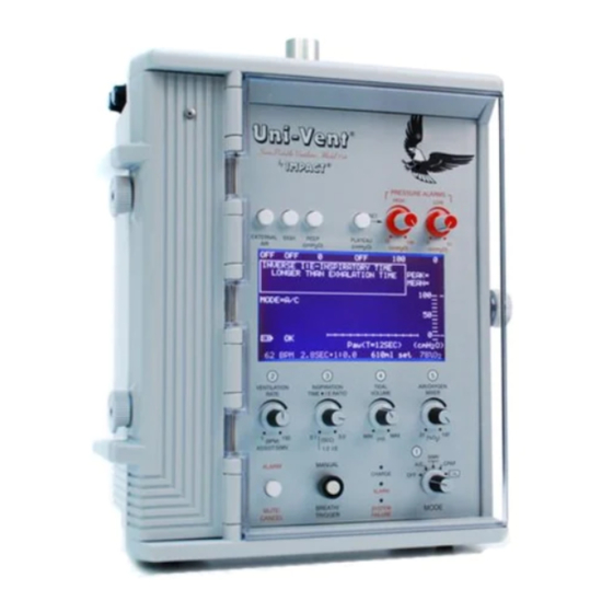
TM
TM
Uni-Vent Eagle
Model 754/754M Portable Ventilator: Description of Controls and Indicators.
PRESSURE PLATEAU OFF/ON Pushbutton Switch:
Default value is "OFF". When switch is pressed,
PLATEAU value is automatically referenced 10
cmH O less than HIGH PRESSURE ALARM/PEAK
2
INSPIRATORY PRESSURE RELIEF Control setpoint.
Plateau range is 5 to 90 cmH O. Value displayed in
2
LCD (beneath Pushbutton Switch).
tm
Uni-Vent
Series Portable Ventilator - Model 754
by
IMPACT
PRESSURE ALARMS
HIGH
LOW
SET
EXTERNAL
SIGH
PEEP
PLATEAU
15
100
0
50
AIR
(cmH O)
(cmH O)
(cmH O)
(cmH O)
2
2
2
2
OFF
OFF
0
OFF
100
0
PEAK= 27
ALARM MESSAGE CENTER
MEAN=
8
100
MODE=A/C
V
= 12.0L
50
min
INSPIRATION
EXT PWR ON
0
- +
OK
P
(T=12 SEC)
(cmH O)
aw
2
.
12 BPM
1.0 SEC 1:4.0
1000ml del
21% O
2
2
3
4
5
VENTILATION
INSPIRATION
TIDAL
AIR/OXYGEN
RATE
TIME
I:E RATIO
VOLUME
MIXER
0.1
3.0
1
150
MIN
MAX
21
100
(BPM)
(SEC)
(ml)
(%O ) 2
ASSIST/SIMV
1:2 I:E
1
SIMV
ALARM
MANUAL
A/C
CPAP
CHARGE
OFF
CAL
ALARM
MUTE/
BREATH/
SYSTEM
MODE
CANCEL
TRIGGER
FAILURE
HIGH PRESSURE ALARM/PEAK INSPIRATORY PRESSURE RELIEF Control:
Sets threshold value for High Pressure Alarm/Peak Inspiratory Pressure Relief.
Range is 15 to 100 cmH O. Default is current postion of Control. Activates
2
when inspiratory pressure exceeds setpoint any time during 4-consecutive
ventilations. Value displayed in LCD (beneath Control).
LOW PRESSURE ALARM Control: Sets threshold
value for Low Pressure Alarm. Range is 0 to 50
cmH O. Default is current postion of Control.
2
Activates when inspiratory pressure does not exceed
setpoint at any time during 2-consecutive ventilations.
Value displayed in LCD (beneath Control).
PEAK and MEAN AIRWAY PRESSURE Indicators: Display
the Peak and MEAN Airway Pressure of the previous breath.
HIGH AIRWAY PRESSURE ALARM Setpoint Indicator: Indicates current
setting of HIGH PRESSURE ALARM Control adjacent to Digital Bar Graph.
DIGITAL BAR GRAPH Indicator: Provides continuous display of airway
pressure. Range is from -10 to +100 cmH O, vertical resolution 2 cmH O/bar.
LOW AIRWAY PRESSURE ALARM Setpoint Indicator: Indicates current
setting of LOW PRESSURE ALARM Control adjacent to Digital Bar Graph.
P Indicator: Displays the most recent 12-seconds of airway pressure
aw
information. Vertical axis is calibrated to coincide with adjacent DIGITAL
BAR GRAPH. Horizontal axis is calibrated in 1-second intervals.
AIR/OXYGEN MIXER Control: Sets FIO when ventilator is connected to
external 50-PSI oxygen source. Range is 21 to 100%. Default is current
position of Control. FIO value displayed in LCD (above Control).
2
TIDAL VOLUME Control: Sets Tidal Volume. Range is based on gas flow not
exceeding 60 LPM (1000 ml/sec). Default value is current position of Control.
Set and delivered Tidal Volume alternately displayed in LCD (above Control).
MODE Selector Switch: Applies operating power to ventilator for Assist-Control
(A/C), Synchronized Intermittent Mandatory Ventilation (SIMV), Continuous
Positive Airway Pressure (CPAP), or Transducer Calibration (CAL) modes.
CHARGE Indicator: Green LED, illuminates when battery recharging current
is flowing. LED does not remain illuminated when battery is fully charged.
ALARM Indicator: Activates for all alarm conditions except a System Failure Alarm. Red
LED flashes on/off when alarm is not muted; stays on continuously when alarm is muted.
The LED Indicator is accompanied by a pulsing tone that remains on until the alarm is muted.
SYSTEM FAILURE Indicator: Activates when CPU is forced to stop operation or a CPU failure
has occurred. Red LED illuminates continuously and is accompanied by a continuous audible
tone that cannot be muted. A System Failure will cause the LCD to blank.
2
2
2
Rev C
(02/98)
Advertisement
Chapters
Table of Contents

Summary of Contents for Impact Instrumentation UNI-VENT Eagle 700 Series
- Page 1 SIGH OFF/ON Pushbutton Switch: Default value is "OFF". When PEEP OFF/ON-SET Pushbutton Switch: HIGH PRESSURE ALARM/PEAK INSPIRATORY PRESSURE RELIEF Control: PRESSURE PLATEAU OFF/ON Pushbutton Switch: set to "ON", first breath delivered is a SIGH, then once every 100- Sets internally-generated PEEP setpoint. Sets threshold value for High Pressure Alarm/Peak Inspiratory Pressure Relief.
- Page 2 MANUAL, OPERATION & SERVICE PORTABLE, SELF-CONTAINED VENTILATION SYSTEM (VENTILATOR, COMPRESSOR, AIR/OXYGEN MIXER) UNI-VENT™ Eagle™ 700 SERIES MODEL 754/754M Impact Instrumentation, Inc. 27 Fairfield Place West Caldwell, New Jersey 07006 © 1997 Impact Instrumentation, Inc. REV. 1.85N (04/05) P/N 906-0754-02...
-
Page 3: Table Of Contents
T A B L E O F C O N T E N T S _____________________________________________________________________________________________ ______________SUBJECT PAGE________ LIST OF ILLUSTRATIONS CONVENTIONS, TERMINOLOGY, DEFINITIONS AND ABBREVIATIONS AS USED IN THIS MANUAL A WORD ABOUT EAGLES SHIPPING CONTENTS ACCESSORIES LIST LIMITED COPYRIGHT RELEASE (MODEL 754M only) viii CALIBRATION/PREVENTATIVE MAINTENANCE NOTICE viii... - Page 4 T A B L E O F C O N T E N T S, (cont'd) _____________________________________________________________________________________________ ______________SUBJECT PAGE________ LED VISUAL INDICATORS STATUS CHARGE ALARM ALARM SYSTEM FAILURE 1-8, 1-9 LCD VISUAL INDICATORS ALARMS - OPERATING BATTERY LOW - EXTERNAL POWER LOW - LOW PRESSURE - DISCONNECT - HIGH PRESSURE - APNEA - HIGH PEEP - O LOW/FAIL - EXT AIR LOW/FAIL - FIO - PRESSURE ALARM...
- Page 5 T A B L E O F C O N T E N T S, (cont'd) _____________________________________________________________________________________________ ______________SUBJECT PAGE________ MODES OF OPERATION ASSIST-CONTROL VENTILATION (ACV) SYNCHRONIZED INTERMITTENT MANDATORY VENTILATION (SIMV) CONTINUOUS POSITIVE PRESSURE VENTILATION (CPAP) CONTROL VENTILATION DURING APNEA USING POSITIVE END EXPIRATORY PRESSURE (PEEP) USING PRESSURE PLATEAU BACKUP VENTILATOR HUMIDIFIERS AND HEAT MOISTURE EXCHANGERS (HME'S)
-
Page 6: List Of Illustrations
T A B L E O F C O N T E N T S, (cont'd) _____________________________________________________________________________________________ ______________SUBJECT PAGE________ ROUTINE CARE: CALIBRATION, CLEANING AND PREVENTATIVE MAINTENANCE CALIBRATION CLEANING PRESSURE HOSE COMPRESSOR INLET FILTER PREVENTATIVE MAINTENANCE BATTERY CARE AND RECHARGING IN CASE OF DIFFICULTY OPERATOR CORRECTABLE PROBLEMS OPERATOR PROBLEMS REQUIRING SERVICE STORAGE INFORMATION... - Page 7 DISPOSABLE CLEAR VENTILATOR PROTECTIVE CIRCUIT DISPLAY DOOR BATTERY COMPARTMENT DOOR 12 VDC POWER CABLE UNIVERSAL AC POWER SUPPLY CARRY HANDLE FUNCTIONAL, INSTRUCTION EASY-TO-USE MANUAL CONTROL PANEL OPERATION AIR HOSE & SERVICE D.I.S.S. X D.I.S.S. OXYGEN HOSE D.I.S.S. X D.I.S.S. Figure 1. Model 754/754M Main Features - v -...
-
Page 8: Conventions, Terminology, Definitions And Abbreviations As Used In This Manual
CONVENTIONS, TERMINOLOGY, DEFINITIONS AND ABBREVIATIONS AS USED IN THIS MANUAL CONVENTIONS WARNING A WARNING message identifies conditions that could have an adverse effect upon the patient or operator. CAUTION A CAUTION statement identifies conditions that could damage this device. NOTE Information immediately following is of sufficient importance that emphasis is made. -
Page 9: A Word About Eagles
The Accessories List contains common items, required from time to time. Each item is preceded by its part number. Accessories may be ordered direct from Impact. When ordering, please include the part number, description and quantity required. Send written purchase orders to: Impact Instrumentation, Inc. Telephonic orders: 973/882-1212 P.O. Box 508 Fax orders:... -
Page 10: Limited Copyright Release (Model 754M Only)
LIMITED COPYRIGHT RELEASE (Model 754M only) Permission is hereby granted to the Department of Defense to reproduce all material furnished under this contract for use in a military service training program and other technical training programs. CALIBRATION/PREVENTATIVE MAINTENANCE NOTICE This device should be incorporated into a regular preventative maintenance program to insure compliance with operating specifications (see LIMITED WARRANTY statement). -
Page 11: Assembly, Interconnections And Initial Adjustments
ASSEMBLY, INTERCONNECTIONS AND INITIAL ADJUSTMENTS ASSEMBLY: Model 754 - No assembly is required before placing this device into operation. Model 754M - Depending upon contract requirements, battery pack installation may be necessary. Please check your contract accordingly. If battery pack installation is required, see BATTERY CARE AND RECHARGING section for instructions. -
Page 12: Interconnection Diagram
INTERCONNECTIONS, (cont’d) 4. Connect Universal AC Power Supply, or 12 VDC Power Cable, between EXTERNAL POWER JACK and external power source (see Figure 5b). NOTE: The standard Universal AC Power Supply is operable from AC voltages between 90 and 265 volts, 47 to 440 Hz. Voltage and line frequency sensing is automatic. -
Page 13: Section I. Operation
SECTION I. OPERATION INTRODUCTION User's will find this instrument quite easy-to-learn and operate. The following text presents a brief overview of device features. A complete understanding of its capabilities and limitations will allow you to take advantage of its many features. Your Model 754/754M is a portable, electronically controlled ventilator, compressor, air/oxygen mixer. -
Page 14: Description Of Controls, Visual Indicators And Connections
FEATURES, (cont’d) Numerical panel markings that indicate sequence-of-operation steps to simplify and speed start-up. Graphics display includes 12-second pressure waveform, its amplitude is calibrated to the adjacent digital bar graph. Automatically compensates pressure transducer to altitude-related barometric pressure changes up to 25,000 ft. -
Page 15: Pressure Alarm/Peak Inspiratory Pressure Relief Control
CONTROLS, (cont'd) EXTERNAL AIR OFF/ON Pushbutton Switch: The EXTERNAL AIR Pushbutton Switch permits you to manually select external compressed air as your primary air source. When the ventilator is turned ON, its CPU "samples" the respective gas fitting and looks for an air pressure, greater than 40-PSI. If a lower pressure, or no pressure is sensed, the LCD will display "OFF"... - Page 16 CONTROLS, (cont'd) VENTILATION RATE Control: The VENTILATION RATE control setting determines the mechanical ventilation rate for ACV and SIMV operation. It is not operable in CPAP (RATE = 0). Its range is from 1 to 150 breaths per minute (BPM). When the ventilator is turned ON, the VENTILATION RATE Control setpoint value equals its current position.
- Page 17 CONTROLS, (cont'd) When the ventilator is turned ON, the AIR/OXYGEN MIXER Control setpoint value equals its current position. Uni-Vent™'s CPU monitors and adjusts gas flow according to the FIO and TIDAL VOLUME setpoints. In CPAP mode, FIO proportions are based on gas flowing at 1000ml/sec. The CPU makes any necessary flow corrections during the first one or two delivered breaths.
-
Page 18: Status
VISUAL INDICATORS When activated, STATUS, and ALARM INDICATORS are continuously displayed. All indicators are displayed within the LCD except for the ALARM, SYSTEM FAILURE, and CHARGE LED's which appear elsewhere on the control panel. When activated, the ALARM and SYSTEM FAILURE LED's illuminate red, the CHARGE LED illuminates green. - Page 19 VISUAL INDICATORS, (cont'd) of operating time capability. Battery icon "ON CHG" is displayed , and the CHARGE LED illuminates, when charging current is flowing into the battery pack. This line will blank if no battery is sensed. OPEN or MISSING FUSES: The POWER INFORMATION CENTER is able to identify open or missing fuses under the following circumstances: 1.
- Page 20 VISUAL INDICATORS, (cont'd) whenever an alarm control is adjusted. Setpoint indicator vertical resolution is 2 cmH O. The respective HIGH or LOW AIRWAY PRESSURE ALARM Setpoint Indicator blinks when a HIGH PRESSURE or LOW PRESSURE Alarm is triggered and blanks when a SYSTEM FAILURE Alarm occurs. Indicator: The P indicator represents a continuous and updating display of airway pressure.
-
Page 21: System Failure
VISUAL INDICATORS, (cont'd) HIGH PEEP Alarm: Initiates when the inspiratory cycle begins before end expiratory pressure plateaus. When activated the AMC displays: HIGH PEEP - INSPIRATION BEGAN BEFORE END PRESSURE PLATEAU or HIGH PEEP. The AMC will blank if a non-operating alarm occurs. LOW/FAIL Alarm: Initiates when low pressure is sensed from an external oxygen supply. -
Page 22: Settings
VISUAL INDICATORS, (cont'd) PLATEAU VOLUME Alarm: Initiates when delivered PRESSURE PLATEAU tidal volume is less than set tidal volume by more than 5%. When activated the AMC displays: PLATEAU VOLUME - DELIVERED VOLUME LESS THAN SET VOLUME. The AMC will blank in the CPAP mode, or if a non-operating alarm occurs. SETTINGS Alarm: Initiates whenever the sum of the flows of the selected gases would exceed a flow rate of 60 liters per minute (LPM). -
Page 23: Disposable Ventilator Circuit
CONNECTIONS, (cont’d) TRANSDUCER HOSE (CONNECTS TO VENTILATOR “TRANSDUCER” GREEN HOSE BARB) GAS DELIVERY HOSE (CONNECTS TO VENTILATOR EXHALATION VALVE “GAS OUT” FITTING) HOSE (CONNECTS TO VENTILATOR “EXHALATION VALVE“ CLEAR HOSE BARB FITTING) EXHALATION VALVE PATIENT CONNECTOR EXHALATION (15mm FEMALE PORT X 22mm MALE) Figure 4. -
Page 24: Operating Power Selection & Stopping
OPERATING POWER SELECTION & STOPPING Uni-Vent™ is designed to operate from various voltages and frequencies (see SPECIFICATIONS). Its Universal AC Power Supply automatically accepts input voltages from 90 to 265 volts AC, 47 to 440 Hz. DC operating voltages, within the range of 11 to 15 volts (negative ground), may be connected directly to the EXTERNAL POWER JACK. -
Page 25: Initial Set-Up, Self -Check And Transducer Calibration
INITIAL SET-UP, SELF-CHECK & TRANSDUCER CALIBRATION INITIAL SET-UP: (Refer to Figures 5a and 5b). Uni-Vent is easily configurable to suit most applications. Additional hoses, fittings and adapters may be required for particular uses. Figures 5a and 5b depict common applications. TEST ALL CONFIGURATIONS FOR CORRECT OPERATION PRIOR TO PATIENT CONNECTION. - Page 26 EXTERNAL GAS SOURCES PIPED PIPED BOTTLED GAS BOTTLED GAS REGULATED REGULATED (AIR) (OXYGEN) 50-PSI OUTPUT 50-PSI OUTPUT COMPRESSOR - OR - - OR - - OR - OXYGEN HIGH PRESSURE HOSE HIGH PRESSURE HOSE D.I.S.S. X D.I.S.S. D.I.S.S. X D.I.S.S. OXYGEN 12 VDC UNIVERSAL...
-
Page 27: Self-Check
SELF-CHECK Uni-Vent™ undergoes a self-checking process every time its MODE Selector Switch is turned from "OFF" to ACV, SIMV, or CPAP; or from CAL to ACV, SIMV, or CPAP. After the initial SELF-CHECK is performed, self- checking is not repeated if the operator turns the MODE Selector Switch to another operating mode position. The SELF-CHECK process consists of interaction between Uni-Vent™'s microprocessor and peripheral circuitry to verify external power/internal battery status, memory check, pressure transducer calibration and control panel settings. -
Page 28: Automatic Calibration (Auto Cal)
TRANSDUCER CALIBRATION, (cont'd) AUTOMATIC CALIBRATION (AUTO CAL) During operation, Eagle™ performs an automatic calibration of its pressure transducer every 5-minutes. This process maintains a consistent transducer baseline over a wide temperature range to assure display, monitoring, and triggering accuracy. If the baseline drifts significantly since the prior AUTO CAL was performed, or the baseline is unstable, Eagle™... - Page 29 USER PROGRAMS, (cont'd) "### Dys" - where "###" represents cumulative days since the last Preventative Maintenance was performed "Version #.##" - where #.## indicates the software version. To enter the USER PROGRAMS menu, simultaneously press MUTE and MANUAL BREATH/TRIGGER Pushbutton Switches while turning the MODE Control Switch to A/C, SIMV, CPAP, or CAL. •...
- Page 30 USER PROGRAMS, (cont'd) SET SPONTANEOUS FLOW: Eagle™'s default Spontaneous Flow is 60 LPM. This USER PROGRAM allows Spontaneous Flow (for use in SIMV or CPAP) to be temporarily changed until operating power is turned OFF. It is adjustable from 10 to 60 LPM in 5 LPM increments. New settings cannot be saved in memory. Once operating power is turned "OFF", Spontaneous Flow is returned to its default value.
-
Page 31: Modes Of Operation
MODES OF OPERATION Your Model 754/754M has been carefully designed to ease the learning transition commonly associated with new instruments. In addition to its clean, uncluttered appearance, Uni-Vent™ includes numerical panel markings to simplify and speed start-up. Only the five primary controls, common to most applications, are marked. They are numbered in order of use, in a 5-step sequence. -
Page 32: Assist-Control Ventilation (Acv)
MODES OF OPERATION, (cont'd) IMPORTANT NOTE The Model 754/754M includes preset trigger sensitivity default. Preset trigger sensitivity default is set between 1.5 and 2.0 cmH O below end pressure. Triggering sensitivity determines how much negative deflection a spontaneously breathing patient must generate before Uni-Vent™ initiates a mechanical breath or demand flow. -
Page 33: Synchronized Intermittent Mandatory Ventilation (Simv)
ASSIST-CONTROL VENTILATION (ACV), (cont'd) ACV operation is permitted in combination with PEEP and/or SIGH, or PEEP and/or PRESSURE PLATEAU (SIGH will become disabled whenever PRESSURE PLATEAU is selected). The following steps are required to initiate ASSIST-CONTROL operation: • 1. Turn MODE Selector Switch to A/C. Allow SELF-CHECK tests to complete. Perform TRANSDUCER CALIBRATION if required (see section entitled TRANSDUCER CALIBRATION). - Page 34 SYNCHRONIZED INTERMITTENT MANDATORY VENTILATION (SIMV), (cont'd) Should the patient become apneic in the SIMV mode, Uni-Vent™ will activate its APNEA Alarm and automatically begin controlled ventilations at its current VENTILATION RATE/INSPIRATORY TIME/TIDAL VOLUME control settings or 12 ventilations per minute/INSPIRATORY TIME/TIDAL VOLUME control settings - whichever is greater (see section entitled CONTROL VENTILATION DURING APNEA;...
-
Page 35: Control Ventilation During Apnea
SYNCHRONIZED INTERMITTENT MANDATORY VENTILATION (SIMV), (cont'd) • 6. Press PLATEAU Pushbutton Switch if SIMV operation with PRESSURE PLATEAU is required. SIGH is automatically disabled (OFF) when PLATEAU is selected. PRESSURE PLATEAU limits peak airway pressure to the PLATEAU level for the duration of an inspiratory cycle. The PRESSURE PLATEAU value is automatically referenced 10 cmH O below the HIGH PRESSURE ALARM/PEAK INSPIRATORY PRESSURE RELIEF Control setting (see section entitled USING... -
Page 36: Using Positive End Expiratory Pressure (Peep)
USING POSITIVE END EXPIRATORY PRESSURE (PEEP) The Model 754/754M is capable of internally controlling PEEP. A separate PEEP valve is not required and must not be added to the disposable patient circuit. The PEEP function provides a means of converting the transducer calibration pressure reference from atmospheric pressure to atmospheric pressure + PEEP pressure. -
Page 37: Backup Ventilator
BACKUP VENTILATOR Eagle™ contains a backup ventilator that is designed to provide a limited degree of operation should a CPU failure occur. A CPU failure is a hardware -detected computer failure that will trigger a SYSTEM FAILURE Alarm. Normal operation will stop, the LCD will blank, the ALARM LED illuminates (flashing), the SYSTEM FAILURE LED illuminates (non-flashing) and a pulsing tone is heard. - Page 38 OPERATOR PERFORMANCE CHECKS, (cont'd) • 1. Verify operating power selections. • 2. When using external power source (from Universal AC Power Supply, or 12 VDC Power Cable) insure that LCD display verifies presence of external power and fuses are not blown or missing. •...
-
Page 39: Alarm Functions
ALARM FUNCTIONS Uni-Vent™ contains numerous alarm circuits, designed to alert attendant personnel and protect the patient. Alarm messages appear in a dedicated area of the LCD display. This area is called the ALARM MESSAGE CENTER (AMC). AMC is the centralized location for alarm information. It consists of a 4-line display area. Each alarm may be displayed with a short, accompanying message (two lines maximum);... - Page 40 OPERATING ALARMS, (cont'd) EXTERNAL POWER LOW Alarm: The EXTERNAL POWER LOW Alarm activates when Uni-Vent™ senses an external power source voltage less than 10.9 VDC at the External Power Input Jack. When activated the AMC displays: EXTERNAL POWER LOW - CHECK POWER SOURCE/CONNECTIONS or EXT PWR. The AMC will blank if a non-operating alarm occurs.
-
Page 41: Alarm Settings
OPERATING ALARMS, (cont'd) APNEA Alarm: The APNEA Alarm is functional in the ACV, SIMV and CPAP modes. When activated in ACV or SIMV, the AMC displays: APNEA - CHECK PATIENT FOR SPONTANEOUS BREATHING or APNEA. When activated in CPAP, the AMC displays: APNEA - CPAP AVERAGE RATE LESS THAN 6-BPM or APNEA. -
Page 42: Non-Operating Alarms
OPERATING ALARMS, (cont'd) Alarm: Initiates when delivered tidal volume is not within 10% of set tidal volume. Its usable range is from 100 to 3000ml. When activated, the TIDAL VOLUME display will alternately flash the "#### set" and " #### del" volumes;... - Page 43 NON-OPERATING ALARMS (cont'd) NO GAS AND COMPRESSOR FAILURE: Occurs when the internal compressor has failed and no external gas(es) are available. The AMC will display: VENTILATOR FAILURE DETECTED FAILURE CODE 2 • NO GAS AND COMPRESSOR FAILURE! EXCESSIVE AIRWAY PRESSURE: Occurs when a continuous pressure, above 100 cmH O, is sensed in the patient circuit for more than 2-seconds.
-
Page 44: Advisory Alarms
ADVISORY ALARMS INSPIRATION TIME TRUNCATED TO 3-SEC Alarm: Initiates when control settings would cause an inspiration time to exceed 3-seconds. It is disabled in the CPAP mode. When activated, operation is allowed to continue, an audible tone is heard and the AMC displays: INSPIRATION TIME TRUNCATED TO 3-SEC-NOTE I-TIME &... -
Page 45: Alarm Muting And Cancelling
ALARM MUTING AND CANCELLING ALARM MUTE/CANCEL Pushbutton Switch: The ALARM MUTE/CANCEL Pushbutton Switch, deactivates the audible portion of an existing OPERATING ALARM for a 30-second period (with the exception of certain power alarm conditions). Mute periods for BATTERY Alarms last for 5-minutes. If an EXTERNAL POWER LOW Alarm occurs and is muted, the mute period will last until the internal battery depletes. -
Page 46: Routine Care: Calibration, Cleaning And Preventative Maintenance
ROUTINE CARE: CALIBRATION, CLEANING, AND PREVENTATIVE MAINTENANCE CALIBRATION This device should be incorporated into a regular preventative maintenance program to insure compliance with operating specifications. Calibration measurements should be made each year unless significant usage warrants a shorter period between preventative maintenance inspections. A comp lete calibration check should be made following each 2000 hours of cumulative use or 12-month period. -
Page 47: Battery Care And Recharging
BATTERY CARE AND RECHARGING The Uni-Vent™ Model 754/754M uses sealed lead-acid batteries, "starved-electrolyte" type, which offer a wide temperature operating range, do not exhibit "memory" characteristics (reduced capacity) or vent hydrogen gas. The life of these batteries depends, to a great extent, upon the care they receive. Following these simple guidelines will prevent premature charge depletion and reduction of battery life. -
Page 48: In Case Of Difficulty
IN CASE OF DIFFICULTY Authorization to service this instrument by other than factory-trained and certified personnel will not be given, nor does Impact Instrumentation, Inc. assume any responsibility and/or liability resulting from such unauthorized servicing. Impact will, upon request, provide competent biomedical engineering departments with service data and schematics. -
Page 49: Storage Information
STORAGE INFORMATION For prolonged storage periods, the Model 754/754M should be stored indoors. The environment should be clean and out of direct sunlight. Storage in non-controlled environments is permissible if batteries are removed. If batteries are not removed, short-term storage temperatures should range between 5°F and 104°F (-15°C to 40°C), relative humidity should be low. - Page 50 SPECIFICATIONS OPERATING MODES: ACV - with/without PEEP, with/without SIGH ACV - with/without PEEP, with/without PRESSURE PLATEAU SIMV - with/without PEEP, with/without SIGH SIMV - with/without PEEP, with/without PRESSURE PLATEAU CPAP - with/without PEEP Control Ventilation - for APNEA backup of ACV, SIMV and CPAP FLOW RATE: Adjustable, 0 to approximately 60 LPM (0 to approximately 1000 ml/SEC) VENTILATION RATE:...
- Page 51 SPECIFICATIONS, (cont'd) LED INDICATOR: CHARGE LCD DIGITAL BAR GRAPH: Range -10 to 100 cmH LCD ALARM DISPLAY: BATTERY LOW, EXTERNAL POWER LOW, LOW PRESSURE, LOW/FAIL, DISCONNECT, HIGH PRESSURE, APNEA, V HIGH PEEP, EXT AIR LOW/FAIL, FIO , INVERSE I/E, COMP, PRESSURE ALARM SETTINGS, TRANSDUCER CALIBRATION ABORT, SYSTEM FAILURE, VENTILATOR FAIL, INSPIRATION TIME TRUNCATED TO 3-SEC, PLATEAU VOLUME,...
- Page 52 SPECIFICATIONS, (cont'd) SIZE: Ventilation System 8.87" Wide X 11.5" High X 4.5" Deep (22.55 cm Wide X 29.21 cm High X 11.43 cm Deep) AC Power Supply (std) 7.75" Wide X 2.62" High X 4.75" Deep (19.69 cm Wide X 6.65 cm High X 12.07 AC Power Supply (opt) 9.75"...
-
Page 53: Limited Warranty
LIMITED WARRANTY When used in accordance with the instructions contained within this Manual, Impact Instrumentation, Inc., warrants this instrument to be free from all defects in materials and workmanship for a period of one (1) year. Batteries, which by their nature are consumable and subjected to environmental extremes, will be warranted only for a period of ninety (90) days. -
Page 54: Preventative Maintenance
SECTION II - SERVICE - TABLE OF CONTENTS _____SUBJECT PAGE SERVICE TECHNICAL DOCUMENTATION ………………………... II - ii INTRODUCTION ……………………………………………………….. 12 - 1 CAUTIONARY NOTE ………………………………………………….. 12 - 1 HELPFUL HINTS ……………………………………………………….. 12 - 1 DISASSEMBLY/REASSEMBLY ………………………………………. 13 - 1 CALIBRATION PROCEDURE …………………………………………. 14 - 1 CIRCUIT DESCRIPTIONS ………………………………………………... - Page 55 SECTION II - SERVICE TECHNICAL DOCUMENTATION FIGURE # DESCRIPTION PAGE Composite Illustration Depicting Major Sub-Assemblies ……………. 18 - 1 Final Mechanical Assembly ………………………………………….. 18 - 2 Final Mechanical Bill of Material .…………………………………... 18 - 3 Display/Switch Panel PCB Schematic ………………………………. 18 - 4 Display/Switch Panel PCB Assembly ……………………………….
- Page 56 TECHNICAL DOCUMENTATION, (cont'd) FIGURE # DESCRIPTION PAGE Reusable Patient Valve Assembly …………………………………… 18 - 39 ---- Reusable Patient Valve Bill of Material ……………………………… 18 - 40 Filter PCB Assembly ………………………………………………… 18 - 41 ---- Filter PCB Bill of Material …………………………………………… 18 - 42 Compressor Air Inlet Assembly …………………….……………….
-
Page 57: Introduction
This device has been classified "life supporting" and "life sustaining" by the United States Food & Drug Administration. If you have not been trained and certified by Impact Instrumentation, Inc., or if you are not a military person trained in the care and servicing of this product, DO NOT attempt to service this device. -
Page 58: Disassembly/Reassembly
DISASSEMBLY/REASSEMBLY TOOLS REQUIRED Screwdriver, Phillips Head, Small Solder (#44 Rosin Core) Screwdriver, Phillips Head, Medium Soldering Iron Soldering Iron (800W) Pliers, Needle Nose - Thin Pliers, Needle Nose - Heavy Heat Sink, (clip -on, or equivalent) Pliers, Soft Jaw (Diamond #529-10) Cable Tie Installation Tool Wire Cutter Nut Driver, #4... - Page 59 SEPARATING UPPER AND LOWER CASE ASSEMBLIES A braided cable is soldered to a lug that is riveted to the Battery Compartment Door. This braid must be carefully removed in order to separate the Upper and Lower Case Assemblies from each other. To remove this braid from the lug, cut and remove enough shrink tubing to expose the braid/lug solder connection.
- Page 60 When mating the Upper Case Assembly (703-0754-06) to Lower Case Assembly (703-0754-05), make sure the Inner wall of Upper Case Assembly (703-0754-06) passes "outside" of Filter PCB (704-0754-03) and Battery Divider tabs align with holes in the Lower Case Assembly (703-0754-05). To reattach braid to solder lug riveted to Battery Compartment Door, first apply a small piece of shrink tubing over the braid.
- Page 61 10. Remove nut and lockwasher securing all Potentiometer Controls (six total) to Front Panel (422-0754-11). 11. Remove Switch Guard (133-0001-00) and two lockwashers securing Manual Trigger Pushbutton Switch to Front Panel (422-0754-11). 12. Remove three 4-40 Keps Nuts (346-0440-01) and four 4-40 x 3/8 Male-to-Female Spacers (368-0029-00) mounting Display/Switch Panel PCB (702-0754-01) to Front Panel (422-0754-11).
- Page 62 Skirt = Red Knob = Gray Cap = Red UPPER CASE ASSEMBLY OUTSIDE VIEW SKIRT, KNOB & CAP LOCATIONS Skirt = Gray Knob = Black Cap = Gray LOWER CASE ASSEMBLY The Lower Case Assembly (703-0754-05) consists of the following essential elements: Flow Manifold and Ribbon Cable, Exhaust Manifold, Filter PCB, Compressor Air Inlet, Compressor and Autocal Valve.
- Page 63 One end of 1/8" ID x 2 1/4" hose (540-0146-00) from Exhaust Manifold (703-0754-04) "Tee" where it connects to black hose barb (480-0235-00) located on front, right side of Lower Case (416-0754-11). One end of 1/8" ID x 1 3/4" hose (540-0160-00) from AUTOCAL Solenoid nickel-plated hose barb (480- 0194-00) where it connects to the white nylon elbow (480-0253-00), a 1/8”...
- Page 64 DISASSEMBLY OF THE COMPRESSOR, AUTOCAL VALVE, AND EXHAUST MANIFOLD FROM LOWER CASE Remove the Compressor Assemb ly (704-0754-05) (includes Autocal Valve Assembly, 704-0754-07), and the Exhaust Manifold Assembly (703-0754-03) as follows: Cut Cable Tie (305-0001-00) connecting ribbon cables from Compressor and Flow Manifold. Remove two 6-32 x 5/16 Phillips Flat Head Screws (357-0632-05-2) securing Autocal Valve Assembly to Compressor.
- Page 65 g. Carefully remove Flow Manifold (703-0754-01) with Connector Sub-Panel (422-0754-41) from Lower Case (416-0754-11). h. Remove Connector Sub-Panel (422-0754-41) from Flow Manifold (703-0754-01). DISASSEMBLY OF THE COMPRESSOR AIR INLET FROM LOWER CASE Remove Compressor Air Inlet Assembly (704-0754-04) from Lower Case (416-0754-11) by removing three 4- 40 x 1/2 Phillips Pan Head Screws (358-0440-08).
- Page 66 Slightly rotate Branch Tee (480-0231-00) and Elbow (480-0232-00) to facilitate removal of Restrictor (478-0003-00) and 5/8" tubing (540-0159-00). Note direction of Restrictor arrow for reassembly. Unscrew Branch Tee (480-0231-00) from exhaust port of Solenoid Valve "A". "A" is the Solenoid closest to the White and Black Elbows (480-0228-00 and 480-0229-00).
- Page 67 3. Remove lower right Hose Barb (480-0226-00) from Compressor. To reassemble, reverse the above steps. DISASSEMBLY OF THE AUTOCAL VALVE Limited disassembly of the Autocal Valve is permissible, as follows: Unscrew two M2 x 0.4 x 16mm Phillips Head Screws securing Solenoid (033-0013-00) to Manifold (470- 0754-61).
-
Page 68: Calibration Procedure
CALIBRATION PROCEDURE COMPUTER CALIBRATION – SOFTWARE VERSION 2.7 Ventilator Uni-Vent Model 754 with M100 or RT200 The calibration software is used for factory and field calibration of the Uni-Vent™ Model 754. Any computer calibration must be followed by a complete operational test. A complete Operation/Verification procedure can be obtained from Impact. - Page 69 NOTE: By default, setup installs the executable file CAL.EXE into directory C:\PROGRAM FILES\IMPACT\M100, and the online help file CAL754.HLP along with this file into subdirectory IMPACT\ HELP. Setup creates two subdirectories in the main directory: IMPACT\Cal754\DOC and IMPACT\ Cal754\ EXPORTS. The DOC subdirectory is used for log files, and the EXPORTS subdirectory for MS EXCEL text delimited files.
- Page 70 Once started, the calibration process runs automatically with little user intervention. At one point of the calibration, “PNT100” will be displayed on the Target (Cal. Point) monitor window (See Figure 1). The technician should then attach a syringe to the 3 leg of the “Tee”...
- Page 71 6. MISCELLANEOUS To change the Operator Name, choose OPERATOR NAME under the SETTINGS submenu. Type the new name in the dialog box and press OK. To fine tune RS232 communications, it is possible to set/change communications timeouts (TIMEOUTS in the SETTINGS submenu).
- Page 72 HARDWARE CALIBRATION 1.0 Overview Hardware Calibration should only be performed after major repair or replacement of the Analog PCB, CPU PCB, Power PCB, or Flow Manifold. It should not be performed as part of routinely scheduled maintenance. Any adjustment in hardware calibration must be followed by a Computer Calibration. Unless proper equipment and expertise is available, hardware calibration should not be attempted and instead be left to properly equipped and trained service personnel.
- Page 73 6 feet of 22mm Tubing 3 pieces of 1/8 ID Tubing (2 ft long ea) Tee- 1/8 hosebarb Syringe, 6 cc Analog PCB Schematic Diagram Air & O2 Pressure sources (cylinders) with Dual Stage regulators (calibrated) Calibration/Test Kit (Impact part number 571-0009-00) 2.0 Set-Up and Procedures 2.1 Connections and Set-Ups Before Beginning, make sure the Model 754 Ventilator is powered off.
- Page 74 4) Turn ON the oxygen valves (1 and 2) located on the Manual Valve Control Test Fixture and adjust the until the flow reaches 60 LPM (measured by the RT-200/M100) 5) Adjust the potentiometer (VR6) to 4.3V 6) Repeat steps 3-5 until both VR5 and VR6 give the correct readings (adjusting one will affect the other).
- Page 75 APPENDIX A: Barometer Calibration Procedure (Above Sea Level) 1.0 Overview Barometer settings shown in the table above apply when calibration is performed at sea-level only. The procedure described below is required when the Ventilator is calibrated at altitudes above sea-level. LET : = calibration site altitude (in feet above sea-level) = atmospheric pressure (in P.S.I.) at calibration site...
- Page 76 Site 2: Given 5000 ft above sea-level = 12.23 (pressure from Table 1 at 5000 feet) 14 − = 2.47 − = -7.53 3. Pressurize to 2.47 PSI and adjust the HI Setting to 4.5V 4. Create a vacuum of 7.53 PSI and adjust the LO Setting to .5V TABLE B ALTITUDE PRESSURE...
-
Page 77: Circuit Descriptions
CIRCUIT DESCRIPTIONS (Refer to attached Schematic and Assembly drawings). 1. DISPLAY/SWITCH PANEL PCB (702-0754-01) The Display/Switch Panel PCB contains the following circuitry: a. MODE SWITCH The Mode Switch (SW11) is a double pole, 5-position switch that connects signals to ground. Each signal has a pullup resistor on the CPU board to bring it to a logic level 1 when not selected by the Mode Switch. - Page 78 2. CPU PCB (702-0754-03) The CPU circuit board can be subdivided into the following sections of circuitry: a. MICROCONTROLLER The microcontroller (U1) is a Phillips 80C552-24 device. It is an 8-bit processor and has an onboard 8 channel A/D converter, RS232 port with internal baud rate generation, two pulse width modulators, and runs on a 20MHz crystal controlled clock.
- Page 79 g. REAL TIME CLOCK The Real Time Clock (U10) contains the maintenance clocks. It keeps track of elapsed time and hours of use since the unit has had its last periodic maintenance, as well as duration of non-use until unit is turned on. A lithium battery on the CPU board powers U10 whenever the instrument is turned off.
- Page 80 latched). Since Output 9 (U10, pin 11) starts out low, the counter’s active low enable pin (U10, pin 13) is also low and counting can begin when the BUAWPRESSUREOK signal goes low. The 555 timer (U11) provides a 2.5Hz clock for the timer. After 4 seconds, the Output 9 signal (pin 11) will switch high if the BUAWPRESSUREOK signal has remained low.
- Page 81 5. POWER PCB (702-0754-04) a. SWITCHING POWER SUPPLY The Switching Power Supply is built around an LM2577 Step-Up Voltage Regulator IC. It is configured as a flyback regulator. The flyback transformer has three secondary windings: +5V, +18V and –18V. The output of the 5V winding is fed back to the regulator IC for closed loop control.
- Page 82 e. FUSE AND POWER SUPPLY MONITOR The Fuse and Power Supply Monitor circuits monitor several voltage points, and activate appropriate alarms when there is a malfunction in the power circuitry. Any time the Mode Switch is moved from the OFF position, Q6 (2N3906: PNP) is turned on since the POWERON signal is connected to ground.
- Page 83 10. UNIVERSAL AC POWER SUPPLY (703-0754-08) The Universal AC Power Supply operates over a nominal input voltage range of 90 – 250VAC, and generates a DC output voltage of nominally 12 Volts. It also incorporates a standard 9-pin RS-232 connector. This connector allows the ventilator to interface with the RS-232 port of a computer.
- Page 84 PREVENTATIVE MAINTENANCE (Refer to ROUTINE CARE AND MAINTENANCE, Section 6, in the Operation portion of this manual) Preventative maintenance inspections (PMI) should be incorporated on a routine basis to insure proper device performance. These inspections should consist of both visual and performance checks, and cleaning when warranted.
- Page 85 Note: A complete Operation/Verification procedure can be obtained from Impact. Call Technical Support 973/882- 1212 or email service@impactii.com. CLEANING: Refer to the ROUTINE CARE AND MAINTENANCE "CLEANING" section in the OPERATION portion of this manual. 16 - 2...
-
Page 86: Troubleshooting Guide
TROUBLESHOOTING GUIDE The following Troubleshooting Guide describes symptoms and their possible causing condition(s). It is strongly recommended that servicing personnel read, and become thoroughly familiar with the operation of this device. INDICATOR PROBLEMS Check for defective LED Check for appropriate signal to LED Check for defective Buzzer Check for appropriate signal to Buzzer Check for defective LCD... - Page 87 GAS DELIV ERY PROBLEMS Check for defective EPLD (U6) Check Flow Manifold Check for defective Transducers Check for leaks Variable Orifice Valves clogged or defective Check Compressor Check for proper output flows Check for leaks Check Exhaust Manifold Check for leaks Exhaust valve(s) defective Antiasphyxia valve not seated or missing Internal hose(s) not connected or leaking...
-
Page 88: Technical Documentation
TECHNICAL DOCUMENTATION NOTE: REFER TO APPLICABLEBILL OF MATERIAL FOR PART NUMBER DESCRIPTION. LOWERCASEASSEMBLY CONNECTORPANELASSEMBLY FILTER PCBASSEMBLY FLOWMANIFOLDASSEMBLY EXHAUSTMANIFOLDASSEMBLY COMPRESSOR AIRINLETASSEMBLY COMPRESSOR ASSEMBLY RIBBON CABLEASSEMBLY AUTOCALVALVEASSEMBLY BATTERYPACK ASSEMBLY UPPERCASEASSEMBLY DISPLAY/SWITCHPANELASSEMBLY PRINTEDCIRCUITBOARDASSEMBLIES FIGURE 6, COMPOSITEILLUSTRATION DEPICTINGMAJORSUB-ASSEMBLIES PAGE 1 8 - 1... - Page 89 Subassemblies & Sealant Not Shown: 14 15 ITEM IMPACTP/N ITEM IMPACTP/N ITEM IMPACT P/N 310-0754-01 340-0064-00 540-0140-00 312-0041-00 358-0440-05 703-0754-05 312-0073-00 358-0632-08 703-0754-06 325-0030-00 376-0007-00 703-0754-07 325-0754-07 376-0019-00 704-0754-01 338-0004-00 480-0253-00 340-0063-00 540-0032-00 SEEBILLOFMATERIAL701-0754-01(PAGE18-3)FORCOMPLETE PART NUMBER DESCRIPTION FIGURE 7, FINAL MECHANICALASSEMBLY PAGE 1 8 - 2...
- Page 90 310-0754-01 SHIELD, EMI 312-0041-00 TAPE, FOAM, WHITE, P/S, 1 1/2" LG 312-0073-00 TAPE, COPPER, 2" W X 8" LG 325-0030-00 LABEL, CALIBRATION/PMI 325-0754-07 LABEL, CAUTION 338-0004-00 RIVET 340-0063-00 GROMMETING, .875 LG 340-0064-00 GROMMET, 5/8" DIA. 358-0440-05 SCREW, PH, PAN HD, 4-40 X 5/16 358-0632-08 SCREW, PH, PAN HD, 6-32 X 1/2 376-0007-00...
- Page 93 ITEM NO. IMPACT P/N ITEM NAME/DESCRIPTION REF DES 027-0010-00 SPEAKER, PIEZO SPK1 029-0006-00 INDUCTOR, FERRITE, 1 1/2 TURN L1,2,3 047-0914-00 DIODE, SIGNAL, 1N914 D3-6,8,10 051-2222-00 TRANSISTOR, NPN, 2N2222 051-3906-00 TRANSISTOR, PNP, 2N3906 Q2,3,4 055-0004-00 IC, TEMP SENSOR, LM34DZ 055-0232-00 IC, RS232 RCVR/DRVR, MAX232 055-2272-00 IC, DUAL OP-AMP, TLC2272 067-0001-00...
- Page 96 ITEM NO. IMPACT P/N ITEM NAME/DESCRIPTION REF DES 047-0914-00 DIODE, SIGNAL, 1N914 047-0914-00 DIODE, SIGNAL, 1N914 047-5818-00 DIODE, SCHOTTKEY, 1N5818 049-5231-05 DIODE, ZENER, 5.1V D1-7 051-2222-00 TRANSISTOR, NPN, 2N2222 051-3906-00 TRANSISTOR, PNP, 2N3906 Q2,3 055-0274-00 IC, LP QUAD OP-AMP, TLC27L4BIN U1,2,3,4 055-0317-00 IC, ADJ VOLT REG, LM317T...
- Page 97 253-1066-41-1 CAP, ELECT, 10UF, 35V, KA C12,20,23 253-1066-41-1 CAP, ELECT, 10UF, 35V, KA 253-4766-21 CAP, ELECT, 47UF, 25V, KA 259-1044-51 CAP, METAL FILM, 0.1UF, 5%, 50V C1,2,10,13,21,24,26 259-1044-51 CAP, METAL FILM, 0.1UF, 5%, 50V C101-105 259-1044-51 CAP, METAL FILM, 0.1UF, 5%, 50V C31,32,33,35,36 266-1003-12 CAP, CERAMIC, 100PF, 100V...
- Page 100 ITEM NO. IMPACT P/N ITEM NAME/DESCRIPTION REF DES 012-0007-00 BUSSWIRE, 22 AWG, 1/2" LG J1,2 021-0021-00 BATTERY, LITHIUM, 3.0V 047-0914-00 DIODE, SIGNAL, 1N914 D1,2,5,6 049-4565-10 DIODE, ZENER, 1N4565 049-5231-05 DIODE, ZENER, 5.1V 051-3906-00 TRANSISTOR, PNP, 2N3906 053-7424-00 IC, TTL, OCTAL BUFFER, 74LS240 U7,8 053-7437-30 IC, TTL, OCTAL LATCH, 74LS373...
- Page 101 240-0754-03 PCB, 4-LAYER, CPU 253-1066-41-1 CAP, ELECT, 10UF, 35V, KA C4,5,8,9,10 253-2256-51 CAP, ELECT, 2.2UF, 50V, KA 253-4766-11 CAP, ELECT, 47UF, 10V, HFS 255-1066-11 CAP, TANTALUM, 10UF, 16V C14,15,16 259-1044-51 CAP, METAL FILM, 0.1UF, 5%, 50V C6,7,13,19,101-115 266-1024-51 CAP, FILM, .001UF, 5%, 50V 266-3303-12 CAP, CERAMIC, 33PF, 5%, 50V C1,2,17...
- Page 104 ITEM NO. IMPACT P/N ITEM NAME/DESCRIPTION REF DES 023-0021-00 TRANSFORMER, RM8 023-0022-00 POWER SUPPLY, LCD, EL, 15V 029-0003-00 INDUCTOR, TOROIDAL, 36uh L2,3 029-0005-00 INDUCTOR, RADIAL, 100uh 037-0003-00 RELAY, SPST, N.O. K1,2 047-0104-00 DIODE, RECT, FAST RECOVERY, FR104 047-0303-00 DIODE, RECTIFIER, FR303 047-0914-00 DIODE, SIGNAL, 1N914 D1,4,12-15,19,20,24-27...
- Page 105 230-0003-00 MOV, 22 VDC, 125A PEAK SURGE 240-0754-04 PCB, 2-LAYER, POWER 252-4776-51-1 CAP, ELECT, HFS, 470UF, 50V, AXIAL 253-1066-41-1 CAP, ELECT, 10UF, 35V, KA 253-1086-11 CAP, ELECT, HFS, 1000UF, 10V 253-2276-21 CAP, ELECT, SU, 220UF, 16V 253-2276-31 CAP, ELECT, HFS, 220UF, 25V C9,12 253-4766-31 CAP, ELECT, HFS, 47UF, 25V...
- Page 108 029-0012-00 INDUCTOR, 330uh, RM4 CORE 029-0015-00 INDUCTOR, 47uh, MOLDED 047-0914-00 DIODE, SIGNAL, 1N914 D10,11,12,15,16,17 047-4002-00 DIODE, RECTIFIER, IN4002 047-5819-00 DIODE, SCHOTTKEY, 1N5819 D1-7 051-0026-00 TRANSISTOR, NPN, DRLNGTN, MPSA26 Q7,13 051-2222-00 TRANSISTOR, NPN, 2N2222 051-3906-00 TRANSISTOR, PNP, 2N3906 Q8,12 051-4400-00 TRANSISTOR, N-CHANNEL, IRFZ44N Q1-6,9 051-9234-00 TRANSISTOR, P-CHANNEL, IRF9Z34...
- Page 109 212-4991-00 RES, M.F.,4.99K, 1/8W, 1% 240-0754-05 PCB, 2-LAYER, MOTOR DRIVE 252-4776-21 CAP, ELECT, SU, 470UF, 16V 253-1056-51-1 CAP, ELECT, 1UF, 50V, KA 253-2266-31 CAP, ELECT, KA, 22UF, 25V 253-4766-51-1 CAP, ELECT, HFS, 47UF, 50V C26,27,28 253-4776-21-1 CAP, ELECT, HFS, 470UF, 16V, RADIAL 255-4766-31 CAP, TANTALUM, 47UF, 25V C103A,105A...
- Page 110 26 23 Not shown Not shown ITEM IMPACTP/N ITEM IMPACTP/N ITEM IMPACT P/N ITEM IMPACTP/N 010-0023-00 340-0052-00 470-0754-11 490-0056-00 016-0056-00 340-0057-00 470-0754-21 602-0006-00 016-0067-00 340-0058-00 470-0754-31 602-0007-00 093-0067-06 340-0061-00 470-0754-41 700-0754-17 240-0754-07 358-0440-08 480-0221-00 700-0754-18 240-0754-08 358-0440-11 480-0222-00 704-0754-06 312-0057-00 358-0440-17 480-0223-00 804-0003-00...
- Page 111 ITEM NO. IMPACT P/N ITEM NAME/DESCRIPTION REF DES 010-0023-00 CABLE, RIBBON, 6-COND, 11 1/2" 016-0056-00 TUBING, SHRINK, 1/4" X 4" LG 016-0067-00 TUBING, SHRINK, 3/16" X 3/4" LG 093-0067-06 CONNECTOR, PLUG, 6-PIN, IDC 240-0754-07 PCB, MANIFOLD INTERFACE, 3-XDCR 240-0754-08 PCB, MANIFOLD INTERFACE, 2-XDCR 312-0057-00 TAPE, TEFLON, 1/4"...
- Page 112 (Located Inside Plug) TEM IMPACT P/N ITEM IMPACTP/N ITEM IMPACTP/N 016-0068-00 099-0013-06 708-0750-01 029-0011-00 099-0014-00 099-0004-02 305-0001-00 SEEBILLOFMATERIAL703-075403(PAGE18-26)FORCOMPLETE PARTNUMBERDESCRIPTION FIGURE 19, DC POWERCABLE PAGE 18-25...
- Page 113 ITEM NO. IMPACT P/N ITEM NAME/DESCRIPTION REF DES 016-0068-00 TUBING, SHRINK, 3/8" X 5/8" LG 029-0011-00 FERRITE, CLAMP ON 099-0004-02 CONNECTOR, AUTO 099-0013-06 PLUG, CABLE, POWER/COMM 099-0014-00 BEND, RELIEF (USE W/099-0013-06) 305-0001-00 CABLE TIE, MINIATURE, 4" LG 708-0750-01 CABLE ASSEMBLY BILL OF MATERIAL: 703-0754-03 18 - 26...
- Page 114 Not shown ITEM IMPACTP/N ITEM IMPACTP/N ITEM IMPACT P/N 010-0021-00 480-0229-00 540-0146-00 016-0056-00 480-0230-00 540-0150-00 093-0068-04 480-0231-00 540-0159-00 357-0440-04 480-0232-00 602-0006-00 414-0754-11 540-0032-00 700-0754-09 478-0003-00 540-0136-00 700-0754-10 480-0227-00 540-0138-00 704-0754-21 480-0228-00 540-0144-00 SEEBILLOFMATERIAL703-0754-04(PAGE18-28)FORCOMPLETE PARTNUMBERDESCRIPTION FIGURE20, EXHAUSTMANIFOLD PAGE 18 - 27...
- Page 115 ITEM NO. IMPACT P/N ITEM NAME/DESCRIPTION REF DES 010-0021-00 CABLE, RIBBON, 4-COND, 9" 016-0056-00 TUBING, SHRINK, 1/4" OD X 4" LG 093-0068-04 CONNECTOR, PLUG, 4-PIN, IDC 357-0440-04 SCREW, PH, FLAT HD, 4-40 X 1/4 414-0754-11 CHASSIS, SOLENOID 478-0003-00 RESTRICTOR, .030 ID X 1/8 X 1/8 BARB 480-0227-00 HOSEBARB, 10-32 X 1/8 TUBE, RED 480-0228-00...
- Page 116 Components 35 36 Mounted t o Underside ofCase: Components Mounted t o Connector Panel (not shown): 09 16 Interconnecting 24 21 Components & Sub-Assemblies (not shown): 22 23 49 50 Not shown 43 44 ITEM IMPACTP/N ITEM IMPACTP/N ITEM IMPACT P/N ITEM IMPACTP/N 016-0004-00 346-...
- Page 117 ITEM NO. IMPACT P/N ITEM NAME/DESCRIPTION REF DES 016-0004-00 TUBING, SHRINK, 3/16" X 1" LG 081-0028-00 FUSE, 10A, 250V, 5X20mm, Fast Acting F1,2 089-0022-00 CONNECTOR, POWER/COMM, 6-PIN 089-0024-00 COVER, SNAP (USE WITH 089-0022-00) 092-0008-00 PIN, FEMALE (USE W/093-0060-08) 099-0010-02 CONNECTOR, PLUG, 2-CONDUCTOR 305-0001-00 CABLE TIE, MINIATURE, 4"...
- Page 118 700-0754-05 JUMPER, 18 AWG, BLUE, 12" 700-0754-06 JUMPER, 18 AWG, BLUE, 3" 700-0754-07 JUMPER, 18 AWG, ORANGE, 12" 700-0754-08 JUMPER, 18 AWG, BROWN, 10" 703-0754-01 ASSY, FLOW MANIFOLD 703-0754-04 ASSY, EXHAUST MANIFOLD 704-0754-03 ASSY, PCB, FILTER 704-0754-04 ASSY, COMPRESSOR AIR INLET 704-0754-05 ASSY, COMPRESSOR BILL OF MATERIAL:...
- Page 119 Interconnecting Components & Sub-Assemblies (not shown) Not Shown ITEM IMPACTP/N ITEM IMPACTP/N ITEM IMPACT P/N ITEM IMPACTP/N 133-0001-00 338-0007-00 392-0025-00 422-0754-11 312-0079-00 346-0440-01 392-0027-00 602-0001-01 312-0085-00 358-0440-04 392-0028-00 602-0007-00 312-0086-00 368-0028-00 392-0030-00 606-0002-00 312-0087-00 368-0029-00 392-0031-00 702-0754-01 312-0088-00 368-0030-00 392-0750-11 702-0754-02 312-0089-00 368-0034-00...
- Page 120 ITEM NO. IMPACT P/N ITEM NAME/DESCRIPTION REF DES 133-0001-00 GUARD, SWITCH, BLACK 312-0079-00 TAPE, FOAM, WHITE, P/S, 5 1/4"LG 312-0085-00 TAPE, COPPER, 2" W X 5 1/2" LG 312-0086-00 TAPE, COPPER, 1" W X 3 1/4" LG 312-0087-00 TAPE, COPPER, 1" W X 3 1/4" LG 312-0088-00 TAPE, COPPER, 1"...
- Page 121 Components Mounted 07 12 20 21 toUndersideofCase: 30 35 Chassis Mounted Components: 33 48 55 17 18 Components Attached t o Not shown Line Cord: 57 58 ITEM IMPACTP/N ITEM IMPACTP/N ITEM IMPACT P/N ITEM IMPACTP/N 006-2013-02 210-0400-02 358-0440-06 414-0754-41 016-0004-00 305-0001-00 358-1032-06...
- Page 122 ITEM NO. IMPACT P/N ITEM NAME/DESCRIPTION REF DES 006-2013-02 CABLE, 77" LG 016-0004-00 TUBING, SHRINK, 3/16" X 1" LG 016-0010-00 TUBING, SHRINK, 3/8" X 1" LG 016-0069-00 TUBING, SHRINK, 3/8" X 2" LG 016-0070-00 TUBING, SHRINK, 1/8" X 3 3/4" LG 016-0071-00 TUBING, SHRINK, 3/16"...
- Page 123 378-0440-08 STANDOFF, SELF-CLINCHING, 4-40 X 1/2 390-0004-00 HANDLE 402-0754-04 CASE, UNIVERSAL AC PWR SUPPLY 404-0021-11 BRACKET, MOUNTING (DOVETAIL) 404-0306-91 BRACKET, SS 404-0754-51 BRACKET, SUPPORT (DOVETAIL) 404-0754-61 BRACKET, MOUNTING, POWER RESISTOR 414-0754-41 CHASSIS 450-0008-00 BUMPER, RUBBER, FOOT, .50 X .12, BLK 602-0001-01 SEALANT, SILICONE RUBBER, RTV 602-0006-00...
- Page 124 ITEM IMPACTP/N ITEM IMPACTP/N ITEM IMPACT P/N 016-0029-00 310-0016-00 700-0754-46 021-0019-00 581-0018-00 099-0009-02 600-0003-00 SEEBILLOFMATERIAL704-0754-01(PAGE18-36)FORCOMPLETE PARTNUMBERDESCRIPTION FIGURE 24, BATTERY PACK ASSEMBLY 18 - 37...
- Page 125 ITEM NO. IMPACT P/N ITEM NAME/DESCRIPTION REF DES 016-0029-00 TUBING, SHRINK, 123mm FLAT X 9 3/4" LG 021-0019-00 BATTERY, LEAD ACID, 6VDC, 5AH B1/B2 099-0009-02 CONNECTOR, PLUG, 2-CONDUCTOR 310-0016-00 INSULATOR, BATTERY, 5AH 581-0018-00 TAPE, MYLAR, CLEAR, 2" W 600-0003-00 GLUE, HOT MELT 700-0754-46 JUMPER, 18 AWG, ORANGE, 3"...
- Page 126 ITEM IMPACTP/N ITEM IMPACTP/N ITEM IMPACT P/N 480-0252-00 490-0024-00 540-0076-00 490-0005-00 490-0025-00 540-0154-00 490-0020-00 490-0027-00 540-0155-00 490-0021-00 490-0062-00 820-0034-00 490-0022-00 490-0061-00 490-0023-00 334-0032-00 SEEBILLOFMATERIAL704-0754-02(PAGE18-40)FORCOMPLETE PARTNUMBERDESCRIPTION NOTE: ITEMS12THRU16ARENOTPARTOFTHISASSEMBLYBUT ARE NECESSARYTOCONNECTPATIENTVALVEASSEMBLYTOVENTILATOR. FIGURE25, REUSABLEPATIENTVALVE ASSEMBLY PAGE 18 - 39...
-
Page 127: Reusable Patient Valve Assembly
ITEM NO. IMPACT P/N ITEM NAME/DESCRIPTION REF DES 480-0252-00 HOSEBARB, 10-32 X 1/8" TUBE, GREEN 490-0005-00 VALVE, LEAF 490-0020-00 VALVE, HOUSING 490-0021-00 EXHALATION CAP, OUTER 490-0022-00 EXHALATION CAP, INNER 490-0023-00 COLLAR, THREADED 490-0024-00 CROSS HAIR 490-0025-00 ELBOW, GAS INLET 490-0027-00 REDUCER, 15MM MALE TO 10MM MALE 490-0062-00 VALVE, DIAPHRAGM... - Page 128 ITEM IMPACTP/N ITEM IMPACTP/N ITEM IMPACT P/N 011-0002-00 029-0013-00 344-0004-00 011-0003-00 092-0008-00 344-0005-00 011-0004-00 093-0060-08 700-0754-11 011-0005-00 093-0062-03 700-0754-12 012-0009-00 240-0754-09 700-0754-13 016-0034-00 255-1056-31 700-0754-14 016-0063-00 259-1044-51 700-0754-15 016-0064-00 312-0078-00 700-0754-16 016-0065-00 344-0001-00 016-0066-00 344-0002-00 SEEBILLOFMATERIAL704-0754-03(PAGE18-42)FORCOMPLETE PARTNUMBERDESCRIPTION FIGURE26, FILTER PCB ASSEMBLY PAGE 18 - 41...
-
Page 129: Filter Pcb Assembly
ITEM NO. IMPACT P/N ITEM NAME/DESCRIPTION REF DES 011-0002-00 BRAID, GND, 1/4" X 9" 011-0003-00 BRAID, GND, 1/4" X 8" 011-0004-00 BRAID, GND, 1/4" X 4" 011-0005-00 BRAID, GND, 1/4" X 2" 012-0009-00 BUSSWIRE, 18 AWG, 1" LG 016-0034-00 TUBING, SHRINK, 1/8" X 1" LG 016-0063-00 TUBING, SHRINK, 1/4"... - Page 130 ITEM IMPACTP/N ITEM IMPACTP/N ITEM IMPACT P/N 312-0021-00 420-0754-21 480-0233-00 340-0019-00 480-0132-00 480-0234-00 370-0008-00 480-0226-00 540-0020-00 SEEBILLOFMATERIAL704-0754-04(PAGE18-44)FORCOMPLETE PARTNUMBERDESCRIPTION FIGURE27, COMPRESSOR AIR INLETASSEMBLY PAGE 18 - 43...
-
Page 131: Compressor Air Inlet Assembly
ITEM NO. IMPACT P/N ITEM NAME/DESCRIPTION REF DES 312-0021-00 TAPE, TEFLON, 1/2" WIDE 340-0019-00 BUSHING, 3/8 ID, 21/32 SHLDR, 7/8 OD 370-0008-00 SPRING, .360 OD X 4 1/4" LG 420-0754-21 HOUSING, COMP, AIR INLET, FILTER 480-0132-00 NIPPLE, CLOSE, 1/2", CHROME 480-0226-00 HOSEBARB, 1/8NPTM X 3/8 ID, 2-BARB 480-0233-00... - Page 132 Not Shown Not Shown ITEM IMPACTP/N ITEM IMPACTP/N ITEM IMPACT P/N 041-0026-00 357-0632-05-2 704-0754-07 305-0001-00 370-0010-00 312-0080-00 540-0142-00 SEEBILLOFMATERIAL704-0754-05(PAGE18-46)FORCOMPLETE PARTNUMBERDESCRIPTION FIGURE 28, COMPRESSOR ASSEMBLY PAGE 18 - 45...
-
Page 133: Compressor Assembly
ITEM NO. IMPACT P/N ITEM NAME/DESCRIPTION REF DES 041-0026-00 COMPRESSOR, DIAPHRAGM 305-0001-00 CABLE TIE, MINIATURE, 4" LG 312-0080-00 TAPE, ELECTRICAL, 3/4" W X 12" LG 357-0632-05-2 SCREW, PH, FLAT HD, 6-32 X 5/16 370-0010-00 SPRING, .360 OD X 3 1/2" LG 540-0142-00 HOSE, PVC, 3/8 ID X 1/2 OD X 4 1/2"... - Page 134 ITEM IMPACTP/N ITEM IMPACTP/N ITEM IMPACTP/N 010-0024-00 092-0010-00 093-0052-14 SEEBILLOFMATERIAL704-0754-06(PAGE18-48)FORCOMPLETE PARTNUMBERDESCRIPTION FIGURE29,RIBBONCABLEASSEMBLY PAGE 18 - 47...
-
Page 135: Ribbon Cable Assembly
ITEM NO. IMPACT P/N ITEM NAME/DESCRIPTION REF DES 010-0024-00 CABLE, RIBBON, 14-COND, 10" 092-0010-00 CONNECTOR, TRANSITION HDR, 10-PIN 093-0052-14 CONNECTOR, PLUG, 14-PIN, IDC BILL OF MATERIAL: 704-0754-06 18 - 48 REV. 0 (05/98) RIBBON CABLE ASSEMBLY... - Page 136 Not shown ITEM IMPACTP/N ITEM IMPACTP/N ITEM IMPACT P/N 016-0040-00 340-0077-00 480-0192-00 033-0013-00 357-0440-05 480-0194-00 093-0082-02 404-0754-41 480-0227-00 340-0062-00 470-0754-61 602-0006-00 SEEBILLOFMATERIAL704-0754-07(PAGE18-50)FORCOMPLETE PARTNUMBERDESCRIPTION FIGURE 30, AUTOCAL VALVE ASSEMBLY PAGE 18 - 49...
-
Page 137: Autocal Valve Assembly
016-0040-00 TUBING, SHRINK, 3/4" ID X 1 1/2" LG 033-0013-00 SOLENOID, 5-VDC, 3-WAY 093-0082-02 CONNECTOR, PLUG, 2-PIN, IDC 340-0062-00 GASKET, NEOPRENE, 1/4" ID X 3/8" OD 340-0077-00 GASKET, SOLENOID 357-0440-05 SCREW, PH, FLAT HD, 4-40 X 5/16 404-0754-41 BRACKET, MTG, AUTOCAL SOLENOID 470-0754-61 MANIFOLD, AUTOCAL SOLENOID 480-0192-00... - Page 138 Not shown-DEPMEDSonly ITEM IMPACTP/N ITEM IMPACTP/N ITEM IMPACT P/N 334-0020-00 703-0754-09 825-0004-00 402-0014-00 704-0754-19 909-0754-04 402-0754-06 820-0067-00 906-0754-02 703-0754-03 825-0002-00 940-0001-00 SEEBILLOFMATERIAL802-0754-02(PAGE18-52)FORCOMPLETE PARTNUMBERDESCRIPTION FIGURE31, ACCESSORY KIT, MODEL 754M PAGE 18 - 51...
-
Page 139: Accessory Kit Assembly
ITEM NO. IMPACT P/N ITEM NAME/DESCRIPTION REF DES 334-0020-00 STRAP, VELCRO, 24" LG 402-0014-00 CASE, PADDED, VENTILATOR & ACC 402-0754-06 CASE, REUSABLE, TRANSIT, 754M (DEPMEDS ONLY) N/A 703-0754-03 ASSY, DC POWER CABLE 703-0754-09 ASSY, POWER SUPPLY, OPTIONAL 704-0754-19 ASSY, KIT, O2 RESERVOIR 820-0067-00 VENTILATOR CIRCUIT, DISPOSABLE 825-0002-00... -
Page 140: Master Bill Of Material
ITEM NO. IMPACT P/N ITEM NAME/DESCRIPTION REF DES 701-0754-01 ASSY, FINAL MECHANICAL 702-0754-01 ASSY, PCB, SWITCH PANEL 702-0754-02 ASSY, PCB, ANALOG 702-0754-03 ASSY, PCB, CPU 702-0754-04 ASSY, PCB, POWER SUPPLY 702-0754-05 ASSY, PCB, MOTOR DRIVE 703-0754-01 ASSY, FLOW MANIFOLD 703-0754-03 ASSY, DC POWER CABLE 703-0754-04 ASSY, EXHAUST MANIFOLD...
Need help?
Do you have a question about the UNI-VENT Eagle 700 Series and is the answer not in the manual?
Questions and answers