
Subscribe to Our Youtube Channel
Summary of Contents for Hirschmann OpEdge-8D
- Page 1 User Manual Installation Industrial Edge Gateway OpEdge-8D Installation OpEdge-8D Technical support Release 01 10/2022 https://hirschmann-support.belden.com...
- Page 2 Control GmbH according to the best of the company's knowledge. Hirschmann reserves the right to change the contents of this document without prior notice. Hirschmann can give no guarantee in respect of the correctness or accuracy of the information in this document.
-
Page 3: Table Of Contents
1.6.2 USB interface Input/output interfaces 1.7.1 Signal contact Installation Checking the package contents Installing and grounding the device 2.2.1 Installing the device onto the DIN rail 2.2.2 Grounding the device Installing an SFP transceiver (optional) Installation OpEdge-8D Release 01 10/2022... - Page 4 Disassembly Removing the device Removing an SFP transceiver (optional) Technical data General technical data Signal contact Power consumption/power output Dimension drawings EMC and immunity Network range Scope of delivery Accessories Underlying technical standards Further support Installation OpEdge-8D Release 01 10/2022...
-
Page 5: Important Information
WARNING WARNING indicates a potentially hazardous situation which, if not avoided, could result in death or serious injury. CAUTION CAUTION indicates a possible danger which, if not avoided, may result in minor injuries. Installation OpEdge-8D Release 01 10/2022... - Page 6 NOTICE NOTICE provides information about procedures that do not involve the risk of injury. Installation OpEdge-8D Release 01 10/2022...
-
Page 7: Safety Instructions
Certified usage Use the product only for the application cases described in the Hirschmann product information, including this manual. Operate the product only according to the technical specifications. See “Technical data” on page 34. Connect to the product only components suitable for the requirements of the specific application case. - Page 8 Qualified personnel receive training on a regular basis. National and international safety regulations Verify that the electrical installation meets local or nationally applicable safety regulations. Installation OpEdge-8D Release 01 10/2022...
- Page 9 Relevant for North America: The power cords are suitable for ambient air temperatures of at least +75 °C (+167 °F). The power cord wires are made of copper. Table 3: Requirements for connecting the supply voltage Installation OpEdge-8D Release 01 10/2022...
- Page 10 In accordance with the above-named EU directive(s), the EU conformity declaration will be at the disposal of the relevant authorities at the following address: Hirschmann Automation and Control GmbH Stuttgarter Str. 45-51 72654 Neckartenzlingen Germany You find the EU conformity declaration as PDF file for downloading on the Internet at: https://www.doc.hirschmann.com/certificates.html...
- Page 11 LED or laser components LED or LASER components according to IEC 60825-1 (2014): CLASS 1 LASER PRODUCT CLASS 1 LED PRODUCT Installation OpEdge-8D Release 01 10/2022...
- Page 12 Recycling note After usage, this device must be disposed of properly as electronic waste, in accordance with the current disposal regulations of your county, state, and country. Installation OpEdge-8D Release 01 10/2022...
-
Page 13: About This Manual
The “Installation” user manual contains a device description, safety instructions, a description of the display, and the other information that you need to install the device. The manual is available for download on the Internet: https:// www.doc.hirschmann.com Installation OpEdge-8D Release 01 10/2022... -
Page 14: Key
The symbols used in this manual have the following meanings: Listing Work step Subheading Installation OpEdge-8D Release 01 10/2022... -
Page 15: Description
The devices provide you with a large range of functions, which the manuals for the operating software inform you about. You will find these manuals in the form of PDF files for downloading on the Internet on the Hirschmann product pages (https://www.doc.hirschmann.com). -
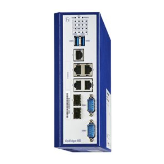
Page 16: Device Views
LED display element 2 × USB interface 5 × Gigabit Ethernet ports (RJ45) for 10/100/1000 Mbit/s Twisted pair connections COM port (DB9 port) COM port (DB9 port) 2 × SFP ports for 1000 Mbit/s fiber optic connections Installation OpEdge-8D Release 01 10/2022... -
Page 17: Right Side View
1.2.2 Right side view 6-pin terminal block connection Grounding screw Installation OpEdge-8D Release 01 10/2022... -
Page 18: Left Side View
You can connect end devices and other segments to the device ports using twisted pair cables or optical fibers (F/O). You find information on pin assignments for making patch cables here: See “Pin assignments” on page 19. Installation OpEdge-8D Release 01 10/2022... -
Page 19: 10/100/1000 Mbit/S Twisted Pair Port
10/100 Mbit/s 1000 Mbit/s MDI mode BI_DA+ TX− BI_DA− BI_DB+ — BI_DC+ — BI_DC− RX− BI_DB− — BI_DD+ — BI_DD− MDI-X mode BI_DB+ RX− BI_DB− BI_DA+ — BI_DD+ — BI_DD− TX− BI_DA− — BI_DC+ — BI_DC− Installation OpEdge-8D Release 01 10/2022... -
Page 20: Display Elements
TX activity — None No data activity (LED on the left) Yellow Lights up Device is transmitting data RX activity — None No data activity (LED on the right) Yellow Lights up Device is receiving data Installation OpEdge-8D Release 01 10/2022... -
Page 21: Management Interfaces
Management interfaces 1.6.1 DB9 port OpEdge-8D devices have a DB9 port for console access. The port is labeled "COM2". The "COM1" port has no functionality in the current release. For information about the position on the device: See “Front view” on page 16. -
Page 22: Input/Output Interfaces
In the process, the device signals events such as a line interruption. When an event occurs, the device opens the relay contact and interrupts the closed circuit. The management setting specifies which events switch a contact. Installation OpEdge-8D Release 01 10/2022... -
Page 23: Installation
Failure to follow these instructions can result in death, serious injury, or equipment damage. 2.2.1 Installing the device onto the DIN rail Note: Verify that there is at least 10 cm (4 in) of space above and below the device. Installation OpEdge-8D Release 01 10/2022... -
Page 24: Grounding The Device
The device has a functional ground connection. The casing is grounded via the separate ground screw on the bottom right of the front panel. Ground the device via the ground screw. Installation OpEdge-8D Release 01 10/2022... -
Page 25: Installing An Sfp Transceiver (Optional)
Installing an SFP transceiver (optional) Prerequisites: Exclusively use Hirschmann SFP transceivers. See “Accessories” on page 41. Figure 2: Installing SFP transceivers: Installation sequence Proceed as follows: Take the SFP transceiver out of the transport packaging (1). Remove the protection cap from the SFP transceiver (2). -
Page 26: Connecting The Power Supply And Signal Lines
Fasten the wires connected by tightening the terminal screws. Signal contact (optional) Connect the wires according to the pin assignment on the device with the clamps. Fasten the wires connected by tightening the terminal screws. Installation OpEdge-8D Release 01 10/2022... -
Page 27: Operating The Device
Note: Relevant for North America: The torque for tightening the supply voltage terminal block and the signal contact terminal block on the OpEdge-8D devices is 0.79 Nm (7 lb-in). The tightening torque for the COM port on the OpEdge-8D devices is 0.79 Nm (7 lb-in). -
Page 28: 1000 Mbit/S F/O Port (Optional)
Ethernet ports: link status is not evaluated (signal contact) Optical ports: Full duplex TP ports: Autonegotiation 2.8.1 First Login (Password) To help prevent undesired access to the device, it is imperative that you change the default password during initial setup. Installation OpEdge-8D Release 01 10/2022... - Page 29 Command Line Interface via the COM2 port. You will find detailed information on factory reset in the software user documentation. You will find the software user documentation as PDF file on the Internet at https:// www.doc.hirschmann.com Installation OpEdge-8D Release 01 10/2022...
-
Page 30: Monitoring The Ambient Air Temperature
The temperature displayed in the GUI is the internal temperature of the device. It is up to +20 °C (+68 °F) higher than the ambient temperature. This depends on the configuration of your device. Installation OpEdge-8D Release 01 10/2022... -
Page 31: Maintenance And Service
Maintenance and service When designing this device, Hirschmann largely avoided using high-wear parts. The parts subject to wear and tear are dimensioned to last longer than the lifetime of the product when it is operated normally. Operate this device according to the specifications. -
Page 32: Disassembly
Disable the supply voltage. Disconnect the terminal blocks. Disconnect the grounding. To remove the device from the DIN rail, press the device downwards and pull it out from under the DIN rail. Installation OpEdge-8D Release 01 10/2022... -
Page 33: Removing An Sfp Transceiver (Optional)
Open the locking mechanism of the SFP transceiver (1). Pull the SFP transceiver out of the slot via the open locking mechanism (2). Close the SFP transceiver with the protection cap (3). Installation OpEdge-8D Release 01 10/2022... -
Page 34: Technical Data
Signal contact Signal contact Connection type 6-pin terminal block Tightening torque 0.79 Nm (7 lb-in) Nominal value = 0.5 A at U = 24 V AC = 0.5 A at U = 48 V DC Installation OpEdge-8D Release 01 10/2022... -
Page 35: Power Consumption/Power Output
Power consumption/power output Device name Maximum Power output power consumption OpEdge-8D 25 W 85 Btu (IT)/h Dimension drawings inch inch 2.56 2.56 0.35 0.35 6.29 6.29 Figure 5: Dimensions of the OpEdge-8D device Installation OpEdge-8D Release 01 10/2022... -
Page 36: Emc And Immunity
Voltage surges - power supply connection EN 61000-4-5 line/ground ± 1 kV EN 61000-4-5 line/line ± 0.5 kV Voltage surges - data line EN 61000-4-5 line/ground ± 1 kV Conducted disturbances EN 61000-4-6 150 kHz ... 80 MHz 10 V Installation OpEdge-8D Release 01 10/2022... -
Page 37: Network Range
Network range Note: The line lengths specified for the transceivers apply for the respective fiber data (fiber attenuation and BLP/ dispersion). Product code Mode Wave length Fiber System Example for F/O line Fiber attenuation BLP M-SFP-... attenuation length dispersion -SX/LC... 850 nm 50/125 µm 0 dB ... - Page 38 Product code Mode Wave length Fiber System Example for F/O line Fiber attenuation BLP M-SFP-... attenuation length dispersion -LH+/LC.. 1550 nm 9/125 µm 13 dB ... 32 dB 38.52 mi ... 72.07 mi 0.25 dB/km 19 ps/(nm×km) (62 km ... 116 km) (typically) -LH+/LC..
- Page 39 10/100/1000 Mbit/s twisted pair port Length of a twisted pair segment max. 100 m (328 ft) (for Cat5e cable) Table 9: Network range: 10/100/1000 Mbit/s twisted pair port Installation OpEdge-8D Release 01 10/2022...
-
Page 40: Scope Of Delivery
Scope of delivery Number Article 1 × Device 1 × Safety and general information sheet 1 × 6-pin terminal block for power supply 1 × 2-pin terminal block for the signal contact Installation OpEdge-8D Release 01 10/2022... -
Page 41: Accessories
SFP-GIG-LX/LC 942 196-001 SFP-GIG-LX/LC EEC 942 196-002 a. Further information on certifications can be found on the Internet at the Hirschmann product pages (www.hirschmann.com). Note: Operate OpEdge-8D devices with fiber optic SFP transceivers only. Copper SFP transceivers are inadmissible. Bidirectional Gigabit Ethernet SFP transceiver... -
Page 42: Underlying Technical Standards
If your device has a shipping approval according to Germanischer Lloyd, you find the approval mark printed on the device label. You will find out whether your device has other shipping approvals on the Hirschmann website under www.hirschmann.com in the product information. -
Page 43: A Further Support
Further support Technical questions For technical questions, please contact any Hirschmann dealer in your area or Hirschmann directly. You find the addresses of our partners on the Internet at http://www.hirschmann.com. A list of local telephone numbers and email addresses for technical support directly from Hirschmann is available at https://hirschmann-support.belden.com.
Need help?
Do you have a question about the OpEdge-8D and is the answer not in the manual?
Questions and answers