Table of Contents
Advertisement
Quick Links
Advertisement
Table of Contents

Summary of Contents for Intech Instruments LPI-LCD-6
- Page 1 LPI-LCD-6 4~20mA Panel Display. Installation Guide.
- Page 2 Setting the Rounding. Page 6 Setting the Units. Page 6 Calibration. Page 7 Backlight. Page 7 Contrast. Page 7 Troubleshooting. The Proper Installation & Maintenance of LPI-LCD-6. Page 8 Page 8 Mounting. Page 8 Wiring. Page 8 Commissioning. Page 8 Maintenance.
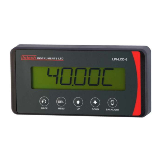
- Page 3 Easy Front Mount Installation. 4~20mA Panel Display. Loop Powered Display Backlight. Description. The LPI-LCD-6 - 4~20mA panel display is ideal for displaying a variety of process variables, and is easy to scale to your required engineering units. Features. Easy installation (front mounting unit takes up virtually no space behind the panel).
- Page 4 LPI-LCD-6 Layout & Dimensions. LPI-LCD-6 Dimensions. 72mm 12mm 144mm 25mm Mounting & Dimensions. This unit is supplied with two stickers to assist with installation. Apply the front sticker if you are drilling from the front of the panel, and back sticker if you are drilling form the back of the panel.
- Page 5 LPI-LCD-6 Terminal Layout. Included with your LPI-LCD-6 is a wiring sticker, which should be applied to the back panels, after the unit has been mounted. The LPI-LCD-6 is powered from the 4~20mA loop input signal and connects to terminal 1 & 2.
- Page 6 LPI-LCD-6 Setup & Calibration. Main Menu. From the operational display area, press the ‘MENU’ button . ‘D.POINT’ will appear on the display. Scroll through the menu items using the ‘UP’ and ‘Down’ buttons . Press to enter the selected menu, or the ‘BACK’ button to go back to your operational display.
- Page 7 Once the 2POINT option has been selected from the Calibration menu, Point1 will appear on the display and toggle with the default display value for the first calibration point (default = 0). Apply the Point 1 input signal to the LPI-LCD-6 display.
- Page 8 Refer to ‘Terminal Layout’ diagrams above for connection information. Commissioning. Once all the above conditions have been carried out and the wiring checked apply power to the LPI-LCD-6 loop and allow five minutes for it to stabilize. Take a low reading (approx. 10%) and high reading (approx. 90%) of the variable being measured by the transducer supplying the signal to the LPI-LCD-6, and ensure that this agrees with the level being indicated by the PLC or indicator, etc., that the LPI-LCD-6 is connected into.
Need help?
Do you have a question about the LPI-LCD-6 and is the answer not in the manual?
Questions and answers