Table of Contents
Advertisement
Quick Links
Installation Manual L6P Load Cell
General
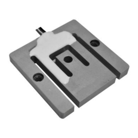
The L6P is an aluminium so called 'Planar Beam' load cell (force sensor), that can be used in a wide array
of applications. A load cell translates a mechanical force into an electrical signal.
Best performance of the Load cell is achieved through adherence to the following provisions and
instructions.
General Design
The low-profile build of the L6P load cell makes it ideal to use in applications where height is a matter of
importance. The load cell is designed in a way so it can be fixed on both left and right side and must be
loaded in the middle. The sensing element is made of high strength Aluminium (colourless anodized for
environmental protection).
The L6P load cell is OIML R60 certified and can therefore also be used in OIML certified applications.
Due to the L6P load cells aluminium body and IP65 protection class is can be used in a wide array of
applications where ingress protection is important.
Installation
Mechanical
To prevent load cells from being damaged during installation, load cells should be handled with care,
especially those with a low rated capacity.
Special attention should be paid in preventing the load cell cable from being damaged during and after
installation. Never carry load cells at their cables and provide dripping loops to prevent direct water
ingress into the cable entry.
Moisture could decrease the insulation resistance of the circuit and might cause unstable readings. A
bag with drying agent (e.g. silica gel ) should be enclosed in the junction box to absorb condensation.
This bag should never make contact with any not-insulated wiring in the junction box.
Also, if more than one load cell is used then the deflection and output of each individual cell should be
similar on each load point.
Preferably the load cell should be mounted on a stiff, rigid & level base that will not deflect while the
system is loaded.
Avoid electric welding after installation of the load cells. If welding is necessary and the load cells cannot
be removed, then disconnect each individual load cell cable from the junction box or measuring device.
Place the earth clamp of the welding apparatus in the close proximity of the weld to avoid a current
path through the load cells.
Specifications and dimensions are subject to change without notice and do not constitute any liability whatsoever.
Nr. 2022.08 Installation Manual L6P Rev0
Page 1/3
Figure 1 shows a type of mounting bracket
design necessary for optimal functioning of
the L6P.
The mounting method is to be provided by
the (end-)customer.
Note the required lower middle area, that
provides space for the middle part of the L6P
to deflect downwards into, when a force is
applied to this part of the L6P.
Figure 1
Zemic Europe B.V.
T: +31 76 50 39480
info@zemic.nl
www.zemiceurope.com
Advertisement
Table of Contents

Summary of Contents for Zemic L6P
- Page 1 Installation Manual L6P Load Cell General The L6P is an aluminium so called ‘Planar Beam’ load cell (force sensor), that can be used in a wide array of applications. A load cell translates a mechanical force into an electrical signal.
- Page 2 Figure 2 Dimensions Be mindful of the following dimensions for mounting the L6P shown in Figure 3, as the middle part (34,50mm wide) needs enough unobstructed clearance for its deflection downward. Also enough space needs to be available underneath the middle part, to accommodate the mounting method (in Figure 3 an M6 bolt is used) plus room underneath the mounting method for the deflection.
- Page 3 Don’t cut the cable at the gland to facilitate removal - please - we cannot test load cells without cables! Zemic Europe B.V. Specifications and dimensions are subject to change without notice and do not constitute any liability whatsoever. T: +31 76 50 39480 info@zemic.nl Nr. 2022.08 Installation Manual L6P Rev0 www.zemiceurope.com Page 3/3...
Need help?
Do you have a question about the L6P and is the answer not in the manual?
Questions and answers