
Subscribe to Our Youtube Channel
Related Manuals for ProSoft MVI56-DFCM

Summary of Contents for ProSoft MVI56-DFCM
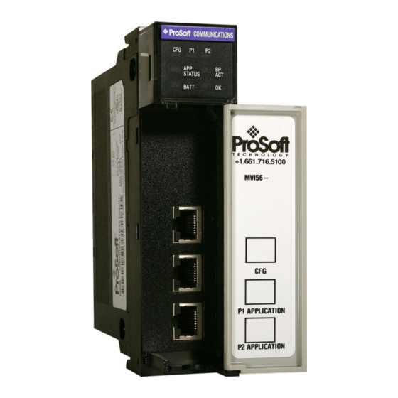
- Page 1 MVI56-DFCM ControlLogix Platform DF1 Half/Full Duplex Master/Slave Serial Communication Module December 3, 2020 USER MANUAL...
-
Page 2: Your Feedback Please
® ProSoft Technology , is a registered copyright of ProSoft Technology, Inc. All other brand or product names are or may be trademarks of, and are used to identify products and services of, their respective owners. In an effort to conserve paper, ProSoft Technology no longer includes printed manuals with our product shipments. -
Page 3: Warnings
MVI56-DFCM ♦ ControlLogix Platform Contents DF1 Half/Full Duplex Master/Slave Serial Communication Module User Manual Warnings North America Warnings Power, Input, and Output (I/O) wiring must be in accordance with Class I, Division 2 wiring methods, Article 501- 4 (b) of the National Electrical Code, NFPA 70 for installation in the U.S., or as specified in Section 18-1J2 of the Canadian Electrical Code for installations in Canada, and in accordance with the authority having jurisdiction. -
Page 4: Table Of Contents
Important Installation Instructions ...................... 2 MVI (Multi Vendor Interface) Modules ....................2 Warnings ............................3 Battery Life Advisory .......................... 3 Guide to the MVI56-DFCM User Manual Start Here System Requirements ....................8 Package Contents ....................8 Setting Jumpers ....................... 9 Installing the Module in the Rack ................ - Page 5 Functional Specifications..................65 Functional Overview ....................66 5.2.1 General Concepts ....................66 5.2.2 Data Flow between MVI56-DFCM Module and ControlLogix Processor ....70 5.2.3 Normal Data Transfer ..................... 74 5.2.4 Configuration Data Transfer Blocks (-9000, -6000 to -6004, -6100 to -6104, 6000 to 6004, 6100- to 6104, and 9000) .....................
-
Page 6: Guide To The Mvi56-Dfcm User Manual
MVI56-DFCM ♦ ControlLogix Platform Start Here DF1 Half/Full Duplex Master/Slave Serial Communication Module User Manual Guide to the MVI56-DFCM User Manual Details Function Section to Read This section introduces the customer to the Introduction Start Here (page 7) module. Included are: package contents,... -
Page 7: Start Here
: install and launch programs, execute menu commands, navigate dialog boxes, and enter data Hardware installation and wiring: install the module, and safely connect DFCM and ControlLogix devices to a power source and to the MVI56-DFCM module’s application port(s) ProSoft Technology, Inc. Page 7 of 97... -
Page 8: System Requirements
Rockwell Automation ControlLogix™ processor, with compatible power supply and one free slot in the rack, for the MVI56-DFCM module. The module requires 800 mA of available power. Rockwell Automation RSLogix 5000 programming software version 2.51 or higher ... -
Page 9: Setting Jumpers
There are three jumpers located at the bottom of the module. The following illustration shows the MVI56-DFCM jumper configuration: Set the PRT 2 (for application port 1) and PRT 3 (for application port 2) jumpers select RS232, RS422, or RS485 to match the wiring needed for your application. -
Page 10: Installing The Module In The Rack
Installing the Module in the Rack If you have not already installed and configured your ControlLogix processor and power supply, please do so before installing the MVI56-DFCM module. Refer to your Rockwell Automation product documentation for installation instructions. Warning: You must follow all safety instructions when installing this or any other electronic devices. Failure to follow safety procedures could result in damage to hardware or data, or even serious injury or death to personnel. -
Page 11: Connecting Your Pc To The Controllogix Processor
MVI56-DFCM ♦ ControlLogix Platform Start Here DF1 Half/Full Duplex Master/Slave Serial Communication Module User Manual Connecting Your PC to the ControlLogix Processor There are several ways to establish communication between your PC and the ControlLogix processor. The following steps show how to establish communication through the serial interface. -
Page 12: Using The Sample Ladder Logic
User Manual Using the Sample Ladder Logic The sample program for your MVI56-DFCM module includes custom tags, data types, and ladder logic for data I/O and status monitoring. For most applications, you can run the sample ladder program without modification, or, for advanced applications, you can incorporate the sample program into your existing application. - Page 13 MVI56-DFCM ♦ ControlLogix Platform Start Here DF1 Half/Full Duplex Master/Slave Serial Communication Module User Manual Connect the straight connector end of the cable to the serial port on your computer. ProSoft Technology, Inc. Page 13 of 97...
-
Page 14: Downloading The Sample Program To The Processor
MVI56-DFCM ♦ ControlLogix Platform Start Here DF1 Half/Full Duplex Master/Slave Serial Communication Module User Manual Downloading the Sample Program to the Processor Note: The key switch on the front of the ControlLogix processor must be in the REM or PROG position. -
Page 15: Configuring The Rslinx Driver For The Pc Com Port
MVI56-DFCM ♦ ControlLogix Platform Start Here DF1 Half/Full Duplex Master/Slave Serial Communication Module User Manual 1.8.1 Configuring the RSLinx Driver for the PC COM Port When trying to connect serially, if RSLogix is unable to establish communication with the processor, follow these steps. - Page 16 MVI56-DFCM ♦ ControlLogix Platform Start Here DF1 Half/Full Duplex Master/Slave Serial Communication Module User Manual Click to select the driver, and then click C . This action opens the Configure ONFIGURE RS-232 DF1 Devices dialog box. Click the A button. RSLinx will attempt to configure your serial port to ONFIGURE work with the selected driver.
-
Page 17: Connecting Your Pc To The Module
The communication port driver in RSLinx can occasionally prevent other applications from using the PC’s COM port. If you are not able to connect to the module’s configuration/debug port using ProSoft Configuration Builder (PCB), HyperTerminal or another terminal emulator, follow these steps to disable the RSLinx driver. - Page 18 MVI56-DFCM ♦ ControlLogix Platform Start Here DF1 Half/Full Duplex Master/Slave Serial Communication Module User Manual Notice how the DF1 driver is opened, and the driver is looking for a processor on Node 1. If the network is being browsed, then you will not be able to stop this driver.
- Page 19 MVI56-DFCM ♦ ControlLogix Platform Start Here DF1 Half/Full Duplex Master/Slave Serial Communication Module User Manual You may now use the COM port to connect to the Config/Debug port of the module. Note: You may need to shut down and restart your PC before it will allow you to stop the driver (usually only on Windows NT machines).
-
Page 20: Using The Rslogix 5000 V16 Add-On Instruction
Download the manuals and sample program from the ProSoft Technology web site You can always download the latest version of the sample ladder logic and user manuals for the MVI56-DFCM module from the ProSoft Technology web site, at www.prosoft-technology.com/support/downloads From that link, navigate to the download page for your module and choose the sample ladder program to download for your version of RSLogix 5000 and your processor. - Page 21 MVI56-DFCM ♦ ControlLogix Platform Using the RSLogix 5000 v16 Add-On Instruction DF1 Half/Full Duplex Master/Slave Serial Communication Module User Manual Select S 0 for the controller. ProSoft Technology, Inc. Page 21 of 97...
-
Page 22: Creating The Module
MVI56-DFCM ♦ ControlLogix Platform Using the RSLogix 5000 v16 Add-On Instruction DF1 Half/Full Duplex Master/Slave Serial Communication Module User Manual Creating the Module Add the MVI56-DFCM module to the project. In the C window, select I/O C and click the ONTROLLER... - Page 23 Parameter DFCM Enter a description for the module. Example: DF1 Half/Full ESCRIPTION Duplex Master/Slave Serial Communication Module Select D -INT ORMAT Enter the slot number in the rack where the MVI56-DFCM module is located NPUT SSEMBLY NSTANCE NPUT UTPUT SSEMBLY...
- Page 24 MVI56-DFCM ♦ ControlLogix Platform Using the RSLogix 5000 v16 Add-On Instruction DF1 Half/Full Duplex Master/Slave Serial Communication Module User Manual Click OK to close the dialog box. Notice that the module now appears in the window. ONTROLLER RGANIZATION ProSoft Technology, Inc.
-
Page 25: Importing The Add-On Instruction Ladder Rung
MVI56-DFCM ♦ ControlLogix Platform Using the RSLogix 5000 v16 Add-On Instruction DF1 Half/Full Duplex Master/Slave Serial Communication Module User Manual Importing the Add-On Instruction Ladder Rung In the C window, expand the T folder and subfolders ONTROLLER RGANIZATION ASKS until you reach the M folder. - Page 26 MVI56-DFCM ♦ ControlLogix Platform Using the RSLogix 5000 v16 Add-On Instruction DF1 Half/Full Duplex Master/Slave Serial Communication Module User Manual Navigate to the location on your PC where you saved the Add-On Instruction (for example, My Documents or Desktop). Select the MVI56DFCM_A X_Y.L5X file...
- Page 27 MVI56-DFCM ♦ ControlLogix Platform Using the RSLogix 5000 v16 Add-On Instruction DF1 Half/Full Duplex Master/Slave Serial Communication Module User Manual When the import is completed, the new rung with the Add-On Instruction will be visible as shown in the following illustration.
-
Page 28: Adding Multiple Modules (Optional)
DF1 Half/Full Duplex Master/Slave Serial Communication Module User Manual Adding Multiple Modules (Optional) Important: If your application requires more than one MVI56-DFCM module in the same project, follow the steps below. In the I/O C folder, click the right mouse button to open a shortcut... - Page 29 MVI56-DFCM ♦ ControlLogix Platform Using the RSLogix 5000 v16 Add-On Instruction DF1 Half/Full Duplex Master/Slave Serial Communication Module User Manual Click OK to confirm. The new module is now visible: Expand the T folder, and then expand the M folder.
- Page 30 MVI56-DFCM ♦ ControlLogix Platform Using the RSLogix 5000 v16 Add-On Instruction DF1 Half/Full Duplex Master/Slave Serial Communication Module User Manual Select the MVI56DFCM_A X_Y.L5X file, and then click I MPORT This action opens the I window, which shows the tags that will...
- Page 31 MVI56-DFCM ♦ ControlLogix Platform Using the RSLogix 5000 v16 Add-On Instruction DF1 Half/Full Duplex Master/Slave Serial Communication Module User Manual 10 Associate the I/O connection variables to the correct module. The default values are Local:1:I and Local:1:O so these require change.
- Page 32 MVI56-DFCM ♦ ControlLogix Platform Using the RSLogix 5000 v16 Add-On Instruction DF1 Half/Full Duplex Master/Slave Serial Communication Module User Manual 11 Change the default tags DFCM and AOI56DFCM to avoid conflict with existing tags. In this step, you should append a string to the default tag names, such as "_2", as shown in the following illustration.
-
Page 33: Ladder Logic
Module Data Object (DFCMModuleDef) All data related to the MVI56-DFCM is stored in a user defined data type. An instance of the data type is required before the module can be used. This is done by declaring a variable of the data type in the Controller Tags Edit Tags dialog box. -
Page 34: Module Definition (Dfcmmodule)
MVI56-DFCM ♦ ControlLogix Platform Ladder Logic DF1 Half/Full Duplex Master/Slave Serial Communication Module User Manual 3.2.1 Module Definition (DFCMModule) Data Type Description Name Start reg to transfer from PLC to module WriteStartReg Number of registers to write from PLC WriteRegCnt... -
Page 35: Df1 Port Parameters (Dfcmport)
MVI56-DFCM ♦ ControlLogix Platform Ladder Logic DF1 Half/Full Duplex Master/Slave Serial Communication Module User Manual 3.2.2 DF1 Port Parameters (DFCMPort) Data Type Description Name 0=Port Disabled,1=Port Enabled Enabled 0=Master, 1=Slave Type 0-254 local station id for device emulated on this port... -
Page 36: Df1 Master Commands (Dfcmcmd)
Number of registers associated with the command Count Swap code used with command Swap Address of device to interface with on the DF1 network Node DF1 function code as defined for MVI56-DFCM module Func First parameter for function Parameter_1 Second parameter for function Parameter_2... -
Page 37: User Data Objects (Dfmc.data)
DF1 Command Set document for a complete list of command parameters. User Data Objects (DFMC.DATA) These objects hold data to be transferred between the processor and the MVI56-DFCM module. User data is read and write data, transferred between the processor and the module as "pages"... -
Page 38: Status Object (Dfcm.status)
MVI56-DFCM ♦ ControlLogix Platform Ladder Logic DF1 Half/Full Duplex Master/Slave Serial Communication Module User Manual Status Object (DFCM.STATUS) This object views the status of the module. The DFCMInStat object shown below is updated each time a read block is received by the processor. Use this data to monitor the state of the module at a "real-time rate". -
Page 39: Special Functions And Controls (Dfcm.control)
MVI56-DFCM ♦ ControlLogix Platform Ladder Logic DF1 Half/Full Duplex Master/Slave Serial Communication Module User Manual Special Functions and Controls (DFCM.CONTROL) The DFCMCONTROL object encapsulates and organizes variables and parameters for several special module functions, as well as slave polling control. - Page 40 MVI56-DFCM ♦ ControlLogix Platform Ladder Logic DF1 Half/Full Duplex Master/Slave Serial Communication Module User Manual Data Type Description Name DFCMSlaveControl Control Slave Polling for Slave SlaveControl Status BOOL Trigger to Enable or Disable Slaves TriggerSlaveControl Slave Address PortNumber Number of Slaves...
-
Page 41: Special Functions And Controls (Dfcm.control)
MVI56-DFCM ♦ ControlLogix Platform Ladder Logic DF1 Half/Full Duplex Master/Slave Serial Communication Module User Manual Special Functions and Controls (DFCM.CONTROL) The DFCMUTIL object encapsulates and organizes variables and parameters used by the ladder logic and Add-On Instruction (AOI) to manage logic flow and optimize backplane block transfers based on user-selected ReadData and WriteData register counts. - Page 42 UPLEX ASTER LAVE ERIAL OMMUNICATION ODULE Select D -INT. Comm Format Enter the slot number in the rack where the MVI56-DFCM Slot module is located. Input Assembly Instance Input Size Output Assembly Instance Output Size Configuration Assembly Instance Configuration Size ProSoft Technology, Inc.
- Page 43 MVI56-DFCM ♦ ControlLogix Platform Ladder Logic DF1 Half/Full Duplex Master/Slave Serial Communication Module User Manual Select the Requested Packet Interval value for scanning the I/O on the module. This value represents the minimum frequency that the module will handle scheduled events.
-
Page 44: Diagnostics And Troubleshooting
MVI56-DFCM ♦ ControlLogix Platform Diagnostics and Troubleshooting DF1 Half/Full Duplex Master/Slave Serial Communication Module User Manual Diagnostics and Troubleshooting In This Chapter LED Status Indicators ................44 Reading Status Data from the Module ........... 49 The module provides information on diagnostics and troubleshooting in the following forms: ... -
Page 45: Led Status Indicators
The battery voltage is low or battery is not present. Allow battery to charge by keeping module plugged into rack for 24 hours. If BAT LED still does not go off, contact ProSoft Technology, as this is not a user serviceable item. - Page 46 If the APP, BP ACT and OK LEDs blink at a rate of every one-second, this indicates a serious problem with the module. Call ProSoft Technology support to arrange for repairs. ProSoft Technology, Inc.
-
Page 47: Clearing A Fault Condition
Verify correct configuration data is being transferred to the module from the ControlLogix controller. If the module's OK LED does not turn GREEN, verify that the module is inserted completely into the rack. If this does not cure the problem, contact ProSoft Technology Technical Support. ProSoft Technology, Inc. -
Page 48: Troubleshooting
DF1 Half/Full Duplex Master/Slave Serial Communication Module User Manual 4.1.2 Troubleshooting Use the following troubleshooting steps if you encounter problems when the module is powered up. If these steps do not resolve your problem, please contact ProSoft Technology Technical Support. Processor Errors Steps to take... -
Page 49: Reading Status Data From The Module
User Manual Reading Status Data from the Module The MVI56-DFCM module returns a 29-word Status Data block that can be used to determine the module’s operating status. This data is located in the module’s database at registers 7600 (N45:0) to 7628 (N45:28) and at the location specified in the configuration. - Page 50 User Manual Navigation All of the submenus in ProSoft Configuration Builder for this module contain commands to redisplay the menu or return to the previous menu. You can always return from a submenu to the next higher menu by pressing [M] on your keyboard.
-
Page 51: Main Menu
Use these commands only if you fully understand their potential effects, or if you are specifically directed to do so by ProSoft Technology Technical Support staff. - Page 52 MVI56-DFCM ♦ ControlLogix Platform Diagnostics and Troubleshooting DF1 Half/Full Duplex Master/Slave Serial Communication Module User Manual Viewing Block Transfer Statistics Press [B] from the Main menu to view the Block Transfer Statistics screen. Use this command to display the configuration and statistics of the backplane data transfer operations between the module and the processor.
- Page 53 Use these commands only if you fully understand their potential effects, or if you are specifically directed to do so by ProSoft Technology Technical Support staff.
- Page 54 Use these commands only if you fully understand their potential effects, or if you are specifically directed to do so by ProSoft Technology Technical Support staff.
-
Page 55: Data Analyzer
MVI56-DFCM ♦ ControlLogix Platform Diagnostics and Troubleshooting DF1 Half/Full Duplex Master/Slave Serial Communication Module User Manual 4.2.3 Data Analyzer The data analyzer mode allows you to view all bytes of data transferred on each port. Both the transmitted and received data bytes are displayed. Use of this feature is limited without a thorough understanding of the protocol. - Page 56 MVI56-DFCM ♦ ControlLogix Platform Diagnostics and Troubleshooting DF1 Half/Full Duplex Master/Slave Serial Communication Module User Manual Viewing Data in Hexadecimal Format Press [H] from the Database View menu to display the data on the current page in hexadecimal format. Viewing Data in ASCII (Text) Format Press [A] from the Database View menu to display the data on the current page in ASCII format.
- Page 57 MVI56-DFCM ♦ ControlLogix Platform Diagnostics and Troubleshooting DF1 Half/Full Duplex Master/Slave Serial Communication Module User Manual Important: When in analyzer mode, program execution will slow down. Only use this tool during a troubleshooting session. Before disconnecting from the Config/Debug port, please press [S] to stop the data analyzer, and then press [M] to return to the main menu.
- Page 58 After selecting the above option, the following window will appear: Next name the file, and select a directory to store the file in. In this example, we are creating a file ProSoft.txt and storing this file on our root C: drive. After you have done this, press the button.
-
Page 59: Database View Menu
MVI56-DFCM ♦ ControlLogix Platform Diagnostics and Troubleshooting DF1 Half/Full Duplex Master/Slave Serial Communication Module User Manual When you have captured the data you want to save, open the Transfer menu and choose Capture Text. On the secondary menu, choose Stop. - Page 60 MVI56-DFCM ♦ ControlLogix Platform Diagnostics and Troubleshooting DF1 Half/Full Duplex Master/Slave Serial Communication Module User Manual Displaying the Current Page of Registers Again Press [S] from the Database View menu to show the current page of registers again. This screen displays the current page of 100 registers in the database.
-
Page 61: Master Command Error List Menu
MVI56-DFCM ♦ ControlLogix Platform Diagnostics and Troubleshooting DF1 Half/Full Duplex Master/Slave Serial Communication Module User Manual Returning to the Main Menu Press [M] to return to the Main menu. 4.2.5 Master Command Error List Menu Use this menu to view the command error list for the module. Press [?] to view a list of commands available on this menu. -
Page 62: Master Command List Menu
MVI56-DFCM ♦ ControlLogix Platform Diagnostics and Troubleshooting DF1 Half/Full Duplex Master/Slave Serial Communication Module User Manual 4.2.6 Master Command List Menu Use this menu to view the command list for the module. Press [?] to view a list of commands available on this menu. -
Page 63: Reference
Automation PLCs and power monitoring equipment, as well as several other third party devices in the marketplace. The MVI56-DFCM module has two Application Serial ports supporting the DF1 protocol, with each port user-configurable to act as a Master or as a slave. Data transfer between the module and the ControlLogix processor is asynchronous to the DF1 network, with the module’s internal database being used to exchange data between the processor and... -
Page 64: Hardware Specifications
MVI56-DFCM ♦ ControlLogix Platform Reference DF1 Half/Full Duplex Master/Slave Serial Communication Module User Manual 5.1.2 Hardware Specifications Description Specification 800 mA @ 5 VDC Backplane Current Load 3 mA @ 24 VDC 0°C to 60°C (32°F to 140°F) Operating Temperature -40°C to 85°C (-40°F to 185°F) -
Page 65: Functional Specifications
Master port or from the processor and is easily transferred to the processor’s data registers. Tested Hardware Connections Several hardware connections have been tested by ProSoft Technology or have been customer field tested. The following physical connections have been tested successfully: ... -
Page 66: Functional Overview
MVI56-DFCM ♦ ControlLogix Platform Reference DF1 Half/Full Duplex Master/Slave Serial Communication Module User Manual Functional Overview 5.2.1 General Concepts The following discussion explains several concepts that are important for understanding module operation. Module Power Up On power up the module begins performing the following logical functions:... - Page 67 Backplane Data Transfer The MVI56-DFCM module communicates directly over the ControlLogix backplane. Data is paged between the module and the ControlLogix processor across the backplane using the module's input and output images. The update frequency of the images is determined by the scheduled scan rate defined by the user for the module and the communication load on the module.
- Page 68 Data contained in this database is paged through the input and output images by coordination of the ControlLogix ladder logic and the MVI56-DFCM module's program. Up to 248 words of data can be transferred from the module to the processor at a time.
- Page 69 MVI56-DFCM ♦ ControlLogix Platform Reference DF1 Half/Full Duplex Master/Slave Serial Communication Module User Manual The block identification codes used by the module are listed below: Descriptions Block Range Configuration data (sent from module) -9000 Port 2 Override File Maps (sent from module)
-
Page 70: Data Flow Between Mvi56-Dfcm Module And Controllogix Processor
Master Driver Mode In Master Mode, the MVI56-DFCM module is responsible for issuing read or write commands to slave devices on the DF1 network. These commands are user configured in the module via the Master Command List received from the ControlLogix processor or issued directly from the ControlLogix processor (event command control). - Page 71 MVI56-DFCM ♦ ControlLogix Platform Reference DF1 Half/Full Duplex Master/Slave Serial Communication Module User Manual Description Step The Master driver obtains configuration data from the ControlLogix processor. The configuration data obtained includes the number of commands and the Master Command List. These values are used by the Master driver to determine the type of commands to be issued to the other nodes on the DF1 network (Refer to the Configuring the Module section).
- Page 72 MVI56-DFCM ♦ ControlLogix Platform Reference DF1 Half/Full Duplex Master/Slave Serial Communication Module User Manual The following table describes the functions supported by the module and the format of each command: Module Information Data Device Information Data Col #...
- Page 73 User Manual Slave Driver Mode The Slave Driver Mode allows the MVI56-DFCM module to respond to data read and write commands issued by a Master on the DF1 network. The following flow chart and associated table describe the flow of data into and out of the module.
-
Page 74: Normal Data Transfer
MVI56-DFCM ♦ ControlLogix Platform Reference DF1 Half/Full Duplex Master/Slave Serial Communication Module User Manual 5.2.3 Normal Data Transfer Normal data transfer includes the paging of the user data found in the module’s internal database in registers 0 to 4999 and the status data. These data are transferred through read (input image) and write (output image) blocks. - Page 75 MVI56-DFCM ♦ ControlLogix Platform Reference DF1 Half/Full Duplex Master/Slave Serial Communication Module User Manual Status Data Definition This section contains a description of the members present in the DFCMSTATUS object. This data is transferred from the module to the processor as part of each Read block.
- Page 76 MVI56-DFCM ♦ ControlLogix Platform Reference DF1 Half/Full Duplex Master/Slave Serial Communication Module User Manual Offset Content Description Parse Block Count This field contains the total number of blocks successfully parsed that were received from the processor. Command Event Block This field contains the total number of command event blocks received from the processor.
-
Page 77: Configuration Data Transfer Blocks (-9000, -6000 To -6004, -6100 To -6104, 6000 To 6004, 6100- To 6104, And 9000)
MVI56-DFCM ♦ ControlLogix Platform Reference DF1 Half/Full Duplex Master/Slave Serial Communication Module User Manual 5.2.4 Configuration Data Transfer Blocks (-9000, -6000 to -6004, -6100 to - 6104, 6000 to 6004, 6100- to 6104, and 9000) When the module performs a restart operation, it will request configuration information from the ControlLogix processor. - Page 78 MVI56-DFCM ♦ ControlLogix Platform Reference DF1 Half/Full Duplex Master/Slave Serial Communication Module User Manual Description Length Offset Command Definition 194 to 205 Command Definition 206 to 217 Command Definition 218 to 229 Command Definition 230 to 241 Spare 242 to 248 -6000 to -6004 and -6100 to -6104 Each of these blocks must be handled by the ladder logic for proper module operation.
- Page 79 MVI56-DFCM ♦ ControlLogix Platform Reference DF1 Half/Full Duplex Master/Slave Serial Communication Module User Manual Master Command List Data Blocks (6000 to 6004 and 6100 to 6104) Each port on the module can be configured as a DF1 Master device containing its own list of one hundred commands.
-
Page 80: Event Command Blocks (1000 Or 2000)
MVI56-DFCM ♦ ControlLogix Platform Reference DF1 Half/Full Duplex Master/Slave Serial Communication Module User Manual 5.2.5 Event Command Blocks (1000 or 2000) Event Command Blocks send DF1 commands directly from the ladder logic to one of the Master ports. The Event Command Write Block format is:... -
Page 81: Slave Status Blocks (3002, 3003, 3102, And 3103)
MVI56-DFCM ♦ ControlLogix Platform Reference DF1 Half/Full Duplex Master/Slave Serial Communication Module User Manual 5.2.6 Slave Status Blocks (3002, 3003, 3102, and 3103) Slave status blocks send status information of each slave device on a Master port. Slaves attached to the Master port can have one of the following states:... - Page 82 MVI56-DFCM ♦ ControlLogix Platform Reference DF1 Half/Full Duplex Master/Slave Serial Communication Module User Manual Ladder logic can be written to override the value in the slave status table to disable slaves (state value of 3) by sending a special block of data from the processor to the slave.
-
Page 83: Command Control Blocks (5000 To 5006 Or 5100 To 5106)
MVI56-DFCM ♦ ControlLogix Platform Reference DF1 Half/Full Duplex Master/Slave Serial Communication Module User Manual 5.2.7 Command Control Blocks (5000 to 5006 or 5100 to 5106) Command control blocks place commands in the command list into the command queue. Each port has a command queue of up to 100 commands. The module services commands in the queue before the Master command list. -
Page 84: Override File Map Configuration Blocks (7000 And 7100, 50 Entries Per Port)
MVI56-DFCM ♦ ControlLogix Platform Reference DF1 Half/Full Duplex Master/Slave Serial Communication Module User Manual 5.2.8 Override File Map Configuration Blocks (7000 and 7100, 50 entries per port) The Override File Mapping feature allows users to assign PCCC-type data table memory addresses (like N10, F8, B3, etc.) to specific areas of the module's user data memory. -
Page 85: Block 9999: Cold Boot
MVI56-DFCM ♦ ControlLogix Platform Reference DF1 Half/Full Duplex Master/Slave Serial Communication Module User Manual Get Module Time (Block 9973) Block Identification Code 9973 is used to requests the module’s date and time. You can use this data to set the ControlLogix clock to match the module's data and time. -
Page 86: Warm Boot Block (9998) Mvi56-Dfcm
Spare 1 to 247 DFCM Database Definition This section contains a listing of the internal database of the MVI56-DFCM module. This information can be used to interface other devices to the data contained in the module. File Start File End... -
Page 87: Basic Command Set Functions
MVI56-DFCM ♦ ControlLogix Platform Reference DF1 Half/Full Duplex Master/Slave Serial Communication Module User Manual Module Information Data Device Information Data Col # Enable Internal Poll Count Swap Node Func Function Parameters Func Code Address Interval Code Address Code... -
Page 88: Plc-5 Command Set Functions
MVI56-DFCM ♦ ControlLogix Platform Reference DF1 Half/Full Duplex Master/Slave Serial Communication Module User Manual 5.3.2 PLC-5 Command Set Functions Command Function Definition PLC5 SLC500 & Power- ControlLogix Function MicroLogix monitor II Code 0x0F 0x00 Word Range Write (Binary Address) 0x0F... - Page 89 MVI56-DFCM ♦ ControlLogix Platform Reference DF1 Half/Full Duplex Master/Slave Serial Communication Module User Manual The PLC-5 and SLC-500 command set require the use of files. These files are emulated in the module. The module defines these files each as containing 200-word registers that overlay the internal database.
-
Page 90: Error Codes
MVI56-DFCM ♦ ControlLogix Platform Reference DF1 Half/Full Duplex Master/Slave Serial Communication Module User Manual Error Codes The module error codes are listed in this section. Error codes returned from the command list process are stored in the command list error memory region. A word is allocated for each command in the memory area. -
Page 91: Errors When Ext Sts Is Present
MVI56-DFCM ♦ ControlLogix Platform Reference DF1 Half/Full Duplex Master/Slave Serial Communication Module User Manual 5.4.3 Errors When EXT STS Is Present Code (Hex) Description Code (Int) 0xF000 Not used -4096 0xF001 A field has an illegal value -4095 0xF002 Less levels specified in address than minimum for any address... -
Page 92: Cable Connections
User Manual Cable Connections The application ports on the MVI56-DFCM module support RS-232, RS-422, and RS- 485 interfaces. Please inspect the module to ensure that the jumpers are set correctly to correspond with the type of interface you are using. - Page 93 MVI56-DFCM ♦ ControlLogix Platform Reference DF1 Half/Full Duplex Master/Slave Serial Communication Module User Manual RS-232: Modem Connection (Hardware Handshaking Required) This type of connection is required between the module and a modem or other communication device. The Use CTS Line parameter for the port configuration should be set to Y for most modem applications.
- Page 94 MVI56-DFCM ♦ ControlLogix Platform Reference DF1 Half/Full Duplex Master/Slave Serial Communication Module User Manual RS-232: Null Modem Connection (No Hardware Handshaking) This type of connection can be used to connect the module to a computer or field device communication port.
-
Page 95: Rs-485 Application Port(S)
MVI56-DFCM ♦ ControlLogix Platform Reference DF1 Half/Full Duplex Master/Slave Serial Communication Module User Manual 5.5.3 RS-422 The RS-422 interface requires a single four or five wire cable. The Common connection is optional, depending on the RS-422 network devices used. The cable required for this interface is shown below: 5.5.4 RS-485 Application Port(s) -
Page 96: Db9 To Rj45 Adaptor (Cable 14)
MVI56-DFCM ♦ ControlLogix Platform Reference DF1 Half/Full Duplex Master/Slave Serial Communication Module User Manual 5.5.5 DB9 to RJ45 Adaptor (Cable 14) ProSoft Technology, Inc. Page 96 of 97... -
Page 97: Support, Service & Warranty
Configuration/Debug status information LED patterns Details about the interfaced serial, Ethernet or Fieldbus devices Note: For technical support calls within the United States, ProSoft’s 24/7 after-hours phone support is available for urgent plant-down issues. Europe / Middle East / Africa Regional Office North America (Corporate Location) Phone: +1.661.716.5100...
Need help?
Do you have a question about the MVI56-DFCM and is the answer not in the manual?
Questions and answers