Advertisement
Quick Links
LED Drivers for LCD Backlights
White Backlight LED Drivers
for Small to Medium LCD Panels
(Switching Regulator Type)
BD60A00NUX, BD60A60NUX
●Description
This IC is boost DC/DC converter that can drive white LED with constant current. More stabled white LED lighting can be
achieved by direct current connection without electric tolerance and High-speed response by current mode. Moreover,
separating IC power supply (2.7V~5.5V) and coil power supply (2.3V~20V) makes it possible to widen input range, which
will be helpful to be applied to various kinds of applications. Over voltage setting can be selected corresponding to the
number of LED lightings. BD60A00NUX is for max 11 lightings, BD60A60NUX is for max 6 lightings.
●Features
1) Boost DC/DC converter
2) Drive LED 11 lightings (VOUT=3.6V×11+0.7V=40.3V <Vf MAX=3.7V>) BD60A00NUX
3) Brightness control by outside PWM signal (PWM frequency =100Hz~30kHz, 25kHz 1% dimming application)
4) Brightness control by DC input
5) Soft start function (1ms typ.)
6) Over voltage protection 42V typ. ( BD60A00NUX), 28Vtyp.( BD60A60NUX)
7) SBD open protection and output short protection
8) Over current protection
9) LED terminal over voltage protection
10) UVLO
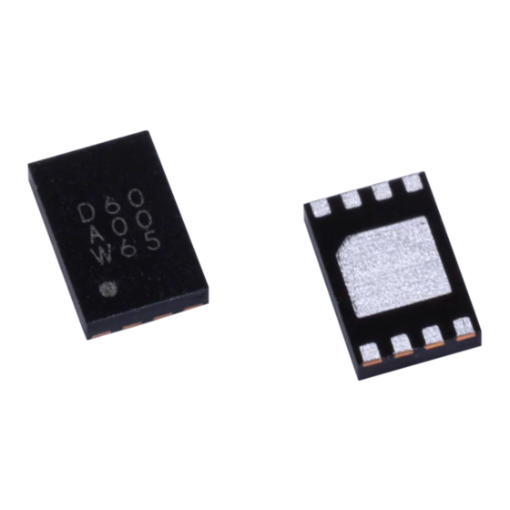
11) VSON008x2030 package (2.0mm × 3.0mm × 0.6mm MAX)
●Applications
Digital video cameras, digital single-lens reflexes, digital still cameras, digital photo frames, personal navigations (PND),
mobile phones, smart phones, MID, PDA, hand-held computers, MP3 players, GPS, digital media players, etc.
●Absolute maximum ratings
Parameter
Maximum applied voltage 1
Maximum applied voltage 2
Maximum applied voltage 2
Operating temperature range
Storage temperature range
Power dissipation 1
*1 4 layer (ROHM Standard board) has been mounted. When it's used by more than Ta=25℃, it's reduced by 20mW/˚C.
●Recommended operating range (Ta=-40℃ ~ +85℃)
Parameter
Operating power supply voltage
Operating coil voltage
*When the operating supply voltage is over 4.61V for BD60A00NUX, please refer the application P.17
www.rohm.com
© 2011 ROHM Co., Ltd. All rights reserved.
Symbol
Ratings
VMAX1
7
VMAX2
45
VMAX3
31
Topr
-40 ~ +85
Tstg
-55 ~ +150
Pd1
2000
Symbol
Ratings
VIN
2.7 ~ 5.5 *
Vcoil
2.3 ~ 20
1/22
BD60A00NUX
Unit
Condition
V
Vin, EN, PWM, ISET terminals
FB, SW, Vout terminals
V
BD60A00NUX
FB, SW, Vout terminals
V
BD60A60NUX
℃
℃
*1
mW
Unit
Conditions
V
Vin terminal
V
Coil voltage
2011.12 - Rev.A
No.11040EAT42
Advertisement

Summary of Contents for Rohm BD60A00NUX
- Page 1 Storage temperature range Tstg -55 ~ +150 ℃ Power dissipation 1 2000 *1 4 layer (ROHM Standard board) has been mounted. When it’s used by more than Ta=25℃, it’s reduced by 20mW/˚C. ●Recommended operating range (Ta=-40℃ ~ +85℃) Parameter Symbol Ratings Unit...
- Page 2 Current Limit Value at LED Current Limit ILOCP ISET Resistor 1kΩ Setting LED Leak Current IqLED μA EN=0V ISET Terminal Voltage Iset *1 This parameter is tested with DC measurement. www.rohm.com 2011.12 - Rev.A 2/22 © 2011 ROHM Co., Ltd. All rights reserved.
- Page 3 Feedback Voltage Input VOUT Over Voltage Protection Input Switching Terminal ●Terminal Diagram P IN P IN G N D G ND G N D Fig.2 Terminal Diagram www.rohm.com 2011.12 - Rev.A 3/22 © 2011 ROHM Co., Ltd. All rights reserved.
- Page 4 BD60A00NUX, BD60A60NUX ●Main characteristics examples 1) Efficiency ●BD60A60NUX <efficiency – ILED> LED 6series, coil : VLF302512MT-100M ●BD60A00NUX <efficiency – ILED> LED 10series, coil : VLF302512MT-100M coil : VLF302512MT-100M www.rohm.com 2011.12 - Rev.A 4/22 © 2011 ROHM Co., Ltd. All rights reserved.
- Page 5 IC Power=5.0V, Coil Power=2.7V to 20V, LED 6serial, LED current =25mA, coil 1094AS-10M(TOKO), SBD RB521A-40TR(ROHM) BD60A60 Vcoil vs efficiency VIN=5V Ta=25℃ LED 6灯(20V) coil 1094AS-10M(TOKO) SBD RB521S-40(Rohm) for BD60A60 LED電流設定 25mA PWM=100% eff=(Vout*ILED)/(Vcoil*Icoil+VINI*VIN)*100 Vcoil (V) www.rohm.com 2011.12 - Rev.A 5/22 © 2011 ROHM Co., Ltd. All rights reserved.
- Page 6 Technical Note BD60A00NUX, BD60A60NUX 100mV/div VOUT LED current 40µs/div PWM 20kHz Duty 50% 100mV/div VOUT LED current 200ns/div PWM 20kHz Duty 1% www.rohm.com 2011.12 - Rev.A 6/22 © 2011 ROHM Co., Ltd. All rights reserved.
- Page 7 LED 8 灯(26V) coil 1094AS-10M(TOKO) 10.00 SBD RB060M-60TR(ROHM) LED current 25mA PWM frequency 20kHz 1.00 0.10 0.01 10.0 100.0 PWM duty (%) 0.4% Possible to Duty 0.4% at PWM=20kHz www.rohm.com 2011.12 - Rev.A 7/22 © 2011 ROHM Co., Ltd. All rights reserved.
- Page 8 Since a soft start function stops working at the time of following PWM=H when EN=H is held with PWM=L After EN=H should input a PWM signal within 10ms. Soft start time Finish Within 10ms Soft Start Soft Start Reset Reset Reset Fig.3 Soft start www.rohm.com 2011.12 - Rev.A 8/22 © 2011 ROHM Co., Ltd. All rights reserved.
- Page 9 Ton = (0.16A × (1-6.0V / 32.5V) × (1 / 0.75MHz) × (10µH /6.0V) × 2) = 0.85µs (1- VIN/VOUT) × (1/fsw)=1.36µs > Ton peak current = (6.0V / 10µH)×0.85µs =0.51A www.rohm.com 2011.12 - Rev.A 9/22 © 2011 ROHM Co., Ltd. All rights reserved.
- Page 10 Moreover, this function can be off by boosting supply voltage up to more than hysteresis voltage. 2.20 V 2.32 V DC/DC Active reset Active Current Driver www.rohm.com 2011.12 - Rev.A 10/22 © 2011 ROHM Co., Ltd. All rights reserved.
- Page 11 VF of LED LED current 20mA Fig. 9 One LED shorted VOUT VOUT LED short 5.9V 0.7V LED current 20mA 0.1mA 100uS Fig.10 FB terminal – VOUT terminal shorted www.rohm.com 2011.12 - Rev.A 11/22 © 2011 ROHM Co., Ltd. All rights reserved.
- Page 12 Normal current setting range is 10mA~30mA, and also LED current at off setting is MAX 2µA of leak current. ISET Normal current setting example RISET LED current 20.0kΩ (E96) 30.0mA 24.0kΩ (E24) 25.0mA 30.0kΩ (E24) 20.0mA 56.0kΩ (E24) 10.7mA www.rohm.com 2011.12 - Rev.A 12/22 © 2011 ROHM Co., Ltd. All rights reserved.
- Page 13 R2 22kΩ ISET 470kΩ 1000 x 0.6V 1000 LED current = 0.6V - DAC output 470kΩ 22kΩ 0.1 0.2 0.3 0.4 0.5 0.6 0.7 DC Voltage [V] www.rohm.com 2011.12 - Rev.A 13/22 © 2011 ROHM Co., Ltd. All rights reserved.
- Page 14 Vout RESET 6.8kΩ ISET 6.49Ω 22kΩ DC (V) 10μH 2.7V to 4.6V Cout 3s7p 2.2μF 4.7μF Vout RESET 33kΩ 5Ω 47kΩ ISET 100kΩ 47nF 0 - 3.3V www.rohm.com 2011.12 - Rev.A 14/22 © 2011 ROHM Co., Ltd. All rights reserved.
- Page 15 ) = 20mA × (5/32.5) ×(1 / 0.6MHz) / (2.2µF×0.5) ripple error = 4.7mV real Output voltage ●LED selection Please select LED VF that input voltage is smaller than output voltage (VOUT). www.rohm.com 2011.12 - Rev.A 15/22 © 2011 ROHM Co., Ltd. All rights reserved.
- Page 16 C、S C、S C、S C、S × C、S C、S C、S C、S ※ C・・・Vcoil-Vin common power supply S・・・Vcoil-Vin separated power supply ×・・・No use due to LED terminal over voltage protection www.rohm.com 2011.12 - Rev.A 16/22 © 2011 ROHM Co., Ltd. All rights reserved.
- Page 17 To select input voltage to 5V(input voltage 4.61V over), we recommend under application to insert 4.7Ω between input voltage line and Vin terminal 10μH 2.7V to 5.5V Cout 4.7Ω 2.2μF 4.7μF Vout PWM Input 25mA RESET ISET RISET 24kΩ www.rohm.com 2011.12 - Rev.A 17/22 © 2011 ROHM Co., Ltd. All rights reserved.
- Page 18 <Others> When those pins are not connected directly near the chip, influence is give to the performance of BD60A00NUX, and limit the current drive performance. As for the wire to the inductor, make its resistance component small so as to reduce electric power consumption and increase the entire efficiency.
- Page 19 Technical Note BD60A00NUX, BD60A60NUX ● Recommended PCB layout www.rohm.com 2011.12 - Rev.A 19/22 © 2011 ROHM Co., Ltd. All rights reserved.
- Page 20 D1: This schottky diode (SBD) is for output rectification. In order to obtain higher switching efficiency, please use low Vf, low reverse leak, and high current capacity. Size Pressure Manufacturer Product Number Vertical Horizontal Height ROHM RB160M-60 ROHM RB521S-40 ROHM RB060M-60 www.rohm.com 2011.12 - Rev.A 20/22 © 2011 ROHM Co., Ltd. All rights reserved.
- Page 21 Perform thermal design in which there are adequate margins by taking into account the permissible dissipation (Pd) in actual states of use. (14) Selection of coil Select the low DCR inductors to decrease power loss for DC/DC converter. www.rohm.com 2011.12 - Rev.A 21/22 © 2011 ROHM Co., Ltd. All rights reserved.
- Page 22 0.08 S 1.5±0.1 C0.25 0.25 Direction of feed 1pin +0.05 0.25 −0.04 Reel ∗ (Unit : mm) Order quantity needs to be multiple of the minimum quantity. www.rohm.com 2011.12 - Rev.A 22/22 © 2011 ROHM Co., Ltd. All rights reserved.
- Page 23 ROHM shall bear no responsibility in any way for use of any of the Products for the above special purposes. If a Product is intended to be used for any such special purpose, please contact a ROHM sales representative before purchasing.
Need help?
Do you have a question about the BD60A00NUX and is the answer not in the manual?
Questions and answers