
Summary of Contents for ALIGNER CCD2.0WIFI
- Page 1 R0368 Cod. R0368 ‐ rev.1.0 (03/2020) WHEEL ALIGNMENT CCD2.0WIFI INSTALLATION AND ASSISTANCE MANUAL FOR TESTING AND CALIBRATIONS RESERVED TO AUTHORISED ASSISTANCE CENTRES ...
- Page 2 (03/2020) 0 INTRODUCTION This manual is intended to provide the installer with complete instructions for the connections and calibration of the "Aligner CCD2.0WiFi" wheel alignment equipment The instructions regarding use and maintenance, reserved for the end user, are collected in the specific manual supplied with the machine or downloadable from the manufacturer's website. ...
-
Page 3: Table Of Contents
R0368 Cod. R0368 ‐ rev.1.0 (03/2020) CONTENTS INTRODUCTION ............................2 0 ASSEMBLY ............................... 2 1 CONNECTIONS ............................3 2 Power line connection ........................3 2.1 ASSOCIATION OF DETECTORS TO THE SERVICE PC ................4 3 THE "connect" WIFI NETWORK ......................6 4 Description and Configuration ......................6 4.1 Initialisation of the front WIFI detectors ................... 6 4.2 Configuration of the default SSID on the front WIFI detectors ............7 4.3 ... -
Page 4: Introduction
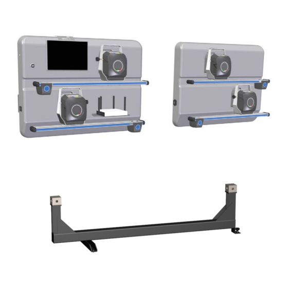
R0368 Cod. R0368 ‐ rev.1.0 (03/2020) 1 ASSEMBLY It is necessary to fix the frames supplied with the equipment on the wall in advance. Use the M8 anchors supplied (4 per frame), fixing them level at a height that is considered practical and functional, as illustrated in Figure 1. It is possible to fix the panels side by side or on two opposite walls, as indicated in chap. 2. Figure 1 Attention: The frames suitable for attachment of the detector panels and those of the bracket panels (optional STDA156) are different from each other. To identify them easily consider that those for detectors have wide vertical strips while those for brackets have narrow vertical strips, as illustrated in Figure 2 Figure 2 Page 2/14... -
Page 5: Connections
R0368 Cod. R0368 ‐ rev.1.0 (03/2020) 2 CONNECTIONS 2.1 Power line connection The alignment sensor panels must be connected to the 115/230Vac 50/60Hz power line; the maximum power used is 100W. Use the power outlet located on the side of the panels. The panels can be connected to the network separately (on two different walls) or the right panel can be powered on the power strip behind the left panel, as in the example in Figure 3. ATTENTION: The power line should not be turned off during the night as the detectors must be recharged. Figure 3 ... -
Page 6: Association Of Detectors To The Service Pc
R0368 Cod. R0368 ‐ rev.1.0 (03/2020) 3 ASSOCIATION OF DETECTORS TO THE SERVICE PC To perform the configuration and calibration of the CCD2.0WiFi detectors, a PC (*) must be used if necessary, with the service SW installed . The CCD20Config service SW can be downloaded from the manufacturer's support site. (*) A PC with S.O. is required Win7 or Win10 with common 802.11b/g/n WLAN Wireless Network card Figure 5 Firstly connect the service PC to the "connect" Wi‐Fi network of the CCD2.0WiFi system, which is generated by the Access Point supplied with the equipment, to which the front detectors and the Tablet are also ... - Page 7 R0368 Cod. R0368 ‐ rev.1.0 (03/2020) The Figure 8 page appears. Pressing the F5 key will start the WIFI search. Figure 8 At the end of the search the references of the detectors found are reported; press F4 to confirm. Figure 9 Attention: if the WiFi search of the detectors does not generate results, try to enable/disable the broadcasting setting; pressing the Alt+F2 keys shows the appearance as set out below: Broadcasting enabled / Broadcasting disabled (default selection) Note: with the access point normally supplied, Zyxel NBG6604, the search is carried out with broadcasting disabled. When the WIFI association is completed, the two icons in the lower right corner turn BLUE. Instead, if the association has not been carried out (or the front detectors are off) these icons are GREY. ...
-
Page 8: The "Connect" Wifi Network
R0368 Cod. R0368 ‐ rev.1.0 (03/2020) 4 THE "connect" WIFI NETWORK 4.1 Description and Configuration The WiFi network of the CCD2.0WiFi set‐up essentially consists of the 2 front detectors connected to the "connect" SSID generated by the access point and the tablet also connected to the "connect" SSID. SSID = connect Figure 10 It is possible to connect the Detectors and the Tablet to a different SSID, useful if for example there are multiple CCD2.0WiFi settings in the same room. To change the name of the SSID on the Access Point, refer to the instructions provided by the ... -
Page 9: Configuration Of The Default Ssid On The Front Wifi Detectors
R0368 Cod. R0368 ‐ rev.1.0 (03/2020) 4.3 Configuration of the default SSID on the front WIFI detectors After connecting the service PC to the WiFi network to be used as default (normally connect) press the Alt + F3 key from the WiFi search page (see Figure 8); access is given to the advanced configuration page, illustrated in Figure 11 Choose the default SSID (normally connect) and confirm with the F5 key. The SSID is shown on the right side, and below If the desired network does not is the password. appear, wait for the page to be Check that the password is correct. automatically refreshed, possibly Normally for SSID connect it is "123connect” enter and exit this page. If necessary correct it. Figure 11 Select the detector from the listed items and confirm with the F5 key The chosen detector is shown in the upper ... -
Page 10: Connection Of Sensors And Internal Devices Of The Detectors
Battery charger cable (with serial cable also connected to JP300) ‐ Wiring code 18390 JP102 Battery Cable (where provided) ‐ Wiring cod. 14144 (label JP11) JP300 Enclosure data connection cable (LOWER SIDE) ‐ Wiring code 18390 JP303 Convergence CCD signal cable ‐ Wiring code 18286 JP304 CCD alignment signal cable ‐ Wiring code 18926 JP301 Detector encoder signal cable (provided only on the rear right detector) Wiring code 18284 JP202 Keypad JP200 Alphanumeric display (not provided on CCD2.0WiFi models) Wiring code 18282 JP302 Service connector XP200 Programming jumper The CPU 20624/20177 board is already integrated with the inclinometer device. A detector equipped with the CPU 20624/20177 can be recognised from the FW version which is 4.0 (or later) ‐ see chap. 6.1. The CPU 20624/20177 can be updated with the FW or configured (as Left/Right front/rear model type etc.) through the dedicated SW tool ... -
Page 11: Calibration
R0368 Cod. R0368 ‐ rev.1.0 (03/2020) 5 CALIBRATION 5.1 Detectors calibration The wheel alignment detectors are already calibrated at the factory; moreover, the calibration values are stored in the CPU memory of the detector itself. Therefore, when installing or replacing a detector, it is not necessary to calibrate or configure the equipment with calibration data. The calibration is performed only in case of replacement of transducers or following ascertained repetitive errors due to movements of transducers (consequently to falls, impacts etc.). Use the following calibration systems according to the models supplied: ... - Page 12 R0368 Cod. R0368 ‐ rev.1.0 (03/2020) Starting from the home page, press the F2 key to enter the Service Menu. Figure 17 Use the F2/F3 keys to select the "Calibration Menu" option, then confirm with F4. Access through the following password: “F8; F7; F6; F8”. Figure 18 Select, using the F3/F2 keys, the "Detector Calibration" option and confirm with the F4 key. Figure 19 If ...
- Page 13 R0368 Cod. R0368 ‐ rev.1.0 (03/2020) The angles that are calibrated are indicated by the following abbreviations, (see Figure 21). AFL Alignment Front Left AFR Alignment Front Right ARL Alignment Rear Left ARR Alignment Rear Right CFL Camber Front Left CFR Camber Front Right CRL Camber Rear Left CRR Camber Rear Right TFL Toe Front Left TFR Toe Front Right TRL Toe Rear Left ...
- Page 14 R0368 Cod. R0368 ‐ rev.1.0 (03/2020) Figure 22 Legend of the Figure 22: 1 ‐ Detectors calibrated in the current phase 2. Current calibration phase 3 ‐ Calibration phases already acquired 4 ‐ Angle calibrated in the current phase with the relative tolerance 5 ‐ Currently read angular value 6 ‐ ...
-
Page 15: Test Procedures
R0368 Cod. R0368 ‐ rev.1.0 (03/2020) 6 TEST PROCEDURES Through the TEST program it is possible to verify the correct operation of all the devices of the wheel alignment system. It is necessary to access the TEST procedures menu by pressing the F2 key from the home page, then selecting the "Test Application" option, the Figure 24 page appears. Figure 24 6.1 Reading the FW release (communication test) The screen shows all the FW versions read by the detectors. ... -
Page 16: Horizontal/Vertical Angles Reading Testi
The screen shows the readings of the angular transducers (encoders) mounted on the detector pins. Turning the pin, it is possible to check that the value read corresponds to the rotation angle made (see Figure 28). The F5 key or grey key on the detector is used to reset the value indicated on the screen. ATTENTION: The CCD2.0WiFi models have the angular transducer (encoder) mounted only on the rear right detector. Figure 28 6.4 Test Keypads The keypads of the 4 detectors are shown on the screen. If a key is repeatedly pressed, the one ...
Need help?
Do you have a question about the CCD2.0WIFI and is the answer not in the manual?
Questions and answers