
Related Manuals for NEURO20 N20 PRO-SYS


Summary of Contents for NEURO20 N20 PRO-SYS
- Page 1 Electro Muscle Stimulation NEURO20 PRO SYSTEM OPERATING MANUAL Version 1.0 © 2022 Neuro20 Technologies ®...
- Page 2 ® Indicates a trademark is registered in the U.S. and other countries. Published by Neuro20 Technologies Corp. 3802 Spectrum Blvd. Suite 116E Tampa, FL 33626 USA +1.917-503-6876 info@neuro20.com www.neuro20.com Copyrighted in the United States of America Product No. Neuro20 PRO System 1.0 Operating Manual: N20PRO-OM-V1.0 07/22...
- Page 3 ® ® Neuro20 PRO System OPERATING MANUAL N20PRO-OM-V1.0 07/22 © NEURO20 TECHNOLOGIES 2022...
- Page 4 Neuro20 PRO System Operating Manual | © Neuro20™ | N20PRO-OM-V1.0 | 07/22 ii | www.neuro20.com...
-
Page 5: Table Of Contents
Neuro20 PRO System Operating Manual | © Neuro20™ | N20PRO-OM-V1.0 | 07/22 TABLE OF CONTENTS SYMBOLS DESCRIPTION..............IV INTRODUCTION................INDICATIONS OF USE...............1 SAFETY.....................2 CONTRAINDICATIONS..............2 WARNINGS..................2 PRECAUTIONS.................5 ADVERSE REACTIONS..............8 PRODUCT DESCRIPTION..............9 SYSTEM COMPONENTS AND OVERVIEW........11 Neuro20 PRO Control Box............12 Battery & Charger..............13 Operating Tablet ..............14... -
Page 6: Symbols Description
Neuro20 PRO System Operating Manual | © Neuro20™ | N20PRO-OM-V1.0 | 07/22 SYMBOLS DESCRIPTION The symbols and their descriptions will appear throughout sections of the Operating Manual. These symbols are associated with the Contraindications, Warnings, Precautions, and potential Adverse Effects. When seeing a symbol read carefully and consider the information prior to operating the equipment. -
Page 7: Introduction
+1.917-503-6876. Proper use and maintenance of the system is the sole responsibility of the registered owner/operator. The Neuro20 PRO System is a medical device not intended for resale, loan, or lease to any third-party operator. Any resale, lease, loan, or distribution of the Neuro20 PRO System may only occur with the written consent of Neuro20 Technologies. -
Page 8: Safety
Neuro20 PRO System Operating Manual | © Neuro20™ | N20PRO-OM-V1.0 | 07/22 SAFETY Contraindications, Warnings, Precautions, Potential Adverse Effects Device User Manual Do not operate this device until the User Manual with the Indications of Use, Contraindications, Warnings, Precautions, and potential Adverse Effects are carefully read and understood. - Page 9 Precaution: Safety of powered muscle stimulators for use during pregnancy has not been established. Menstruation Do not use the Neuro20 electrical system over the lumbar or abdominal regions or over the uterus during menstruation as stimulation may temporarily increase menstrual flow.
- Page 10 Explosion hazard exists if the Neuro20 PRO System is used in the presence of flammable anesthetics mixture with air, oxygen, or nitrous oxide. External Stimulator Systems Electrical stimulation should not be applied directly over external stimulator systems with lead wires.
-
Page 11: Precautions
Neuro20 PRO System Operating Manual | © Neuro20™ | N20PRO-OM-V1.0 | 07/22 WARNINGS (continued) User Activity Portable powered muscle stimulators should not be used while driving, operating machinery, or during any activity in which involuntary muscle contractions may put the user at undue risk of injury. Do not use when bathing or swimming. - Page 12 Neuro20 PRO System Operating Manual | © Neuro20™ | N20PRO-OM-V1.0 | 07/22 PRECAUTIONS (continued) Lead Wires Never connect lead wires to a power line or electro-surgery equipment. Powered muscle stimulators should be used only with the leads and electrodes recommended for use by the manufacturer.
- Page 13 Control Box, or suit connection. Condensation Sudden temperature changes can cause condensation to build up inside of the stimulator, allow for the Neuro20 PRO Control Box to reach ambient temperature before use. Strangulation can occur due to length of exposed component materials. Do not wrap any exposed component part around the throat or neck area.
-
Page 14: Adverse Reactions
Neuro20 encourages all patients to report any adverse reactions to their healthcare professional and then via email to info@neuro20.com. Neuro20 will keep a record of all adverse reaction reports in order to maintain updates, transparency, and public safety at all times and only share information to meet any necessary regulatory requirements. -
Page 15: Product Description
The system will actively recruit multiple muscle fibers per repetition and enhance movement patterns for quicker muscle education. The Neuro20 PRO System may also be used for muscle recovery in the form of passively stimulating the muscles in a pattern that is both relaxing and cleansing of metabolic waste significantly deceasing the effects of delayed onset muscle soreness (DOMS). - Page 16 Neuro20 PRO System Operating Manual | © Neuro20™ | N20PRO-OM-V1.0 | 07/22 Model Number: N20 PRO-SYS The Neuro20 PRO System is designed to be operated for sessions for 1-10 users at a time. One Control Box is assigned per user and attaches to each user’s Smart Suit.
-
Page 17: System Components And Overview
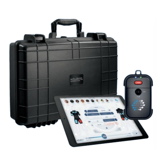
Neuro20 PRO System Operating Manual | © Neuro20™ | N20PRO-OM-V1.0 | 07/22 SYSTEM COMPONENTS AND OVERVIEW Neuro20 PRO System Components: • Neuro20 PRO Control Box - Model Number: N20PRO-CB • Neuro20 PRO Software 1.0 - Model Number: N20PRO-SW • Neuro20 Smart Suit 1.0 - Model Number: N20-SS •... -
Page 18: Neuro20 Pro Control Box
(continued) Neuro20 PRO Control Box - Model Number: N20PRO-CB The Neuro20 PRO Control Box is a powered muscle stimulator that attaches to the Smart Suit. The Control Box generates electrical impulses and is controlled by the operator through the Software installed on the Operating Tablet. The Control Box wirelessly connects to operating tablet. -
Page 19: Battery & Charger
Neuro20 PRO System Operating Manual | © Neuro20™ | N20PRO-OM-V1.0 | 07/22 SYSTEM COMPONENTS AND OVERVIEW (continued) Battery & Charger The battery & charger (LP-E5 battery, model LF7.4900) for the Neuro20 PRO Control Box are provided by a 3rd party provider. -
Page 20: Operating Tablet
Neuro20 PRO System Operating Manual | © Neuro20™ | N20PRO-OM-V1.0 | 07/22 SYSTEM COMPONENTS AND OVERVIEW (continued) Operating Tablet – (Apple iPad, 9th generation) The Operating Tablet comes with pre-installed Neuro20 PRO Software. The tablet wirelessly connects to the Neuro20 PRO Control Box and operates the Neuro20 PRO Software. -
Page 21: Neuro20 Smart Suit
The suits are unisex in sizes ranging from XS to XXXL. Do not use, or attempt to use any other stimulation suit with the Neuro20 PRO system. Neuro20 Smart Suit... - Page 22 Neuro20 PRO System Operating Manual | © Neuro20™ | N20PRO-OM-V1.0 | 07/22 SYSTEM COMPONENTS AND OVERVIEW (continued) Neuro20 Smart Suit - Model Number: Neuro20-SS (continued) Electrodes (pads) on the Neuro20 Smart Suit fit over the following muscle groups. Neuro20 Smart Suit - Electrodes / Muscle Group Diagram...
-
Page 23: Operating Procedures
Neuro20 PRO System Operating Manual | © Neuro20™ | N20PRO-OM-V1.0 | 07/22 OPERATING PROCEDURES Neuro20 Smart Suit Upon opening the package inspect the suit to ensure there are no exposed wires, holes, or tears. Putting on the Neuro20 Smart Suit •... - Page 24 Control Box. Make sure that the latch at the top of the hip clip is open (in the vertical position). 2. Align the slide and guide rails of the of the Neuro20 PRO Control Box with the rails on the hip clip of the Smart Suit.
- Page 25 Neuro20 PRO System Operating Manual | © Neuro20™ | N20PRO-OM-V1.0 | 07/22 OPERATING PROCEDURES (continued) Attaching Neuro20 PRO Control Box (continued) www.neuro20.com | 19...
- Page 26 OPERATING PROCEDURES (continued) Detaching the Neuro20 PRO Control Box 1. Press the Neuro20 PRO Control Box Power Button and ensure that the indicator lights are off. 2. Open the Velcro fastening strap attached to the suit, close the hook and pile strap to each other and ensure that it is no longer through the fastener.
- Page 27 Software Registration and Owners Profile Setup Power on the Operating Tablet by pressing the power button, then press the home button.. Power Button Home Button Open the Neuro20 PRO Software by tapping the icon at the bottom of the screen. www.neuro20.com | 21...
- Page 28 Neuro20 PRO System Operating Manual | © Neuro20™ | N20PRO-OM-V1.0 | 07/22 OPERATING PROCEDURES (continued) Log-In Screen Once the user opens the tablet app, the following screen shall appear: Once the device is registered at www.neuro20.com then Enter your e-mail and Password and press Sign-In.
- Page 29 Neuro20 PRO System Operating Manual | © Neuro20™ | N20PRO-OM-V1.0 | 07/22 OPERATING PROCEDURES (continued) Main screen After logging in, the following main screen appears: Figure 9 The software version of the tablet software appears in the bottom-left corner. Three buttons appear: Manage Profiles, Manage Devices and Start Training.
- Page 30 Neuro20 PRO System Operating Manual | © Neuro20™ | N20PRO-OM-V1.0 | 07/22 OPERATING PROCEDURES (continued) Profile Management This section describes the Profile Management functionality of the Neuro20 PRO Software. This section allows the Own/Manager to control and manage those assigned to the individual Neuro20 PRO Control Boxes and suits.
- Page 31 OPERATING PROCEDURES (continued) Importing a User This option allows the user to import a member assigned to a different Neuro20 PRO System. The import function is accessible via the Import Profile or QR code buttons: 1. Click the Import Profile button to open the Operating Tablet’s camera.
- Page 32 Neuro20 PRO System Operating Manual | © Neuro20™ | N20PRO-OM-V1.0 | 07/22 OPERATING PROCEDURES (continued) Search function If the user clicks the Search Icon, a pane shall appear on the right-hand side, showing the profiles in the device database. The Search tool allows the manager to look for specific profile names.
- Page 33 Neuro20 PRO System Operating Manual | © Neuro20™ | N20PRO-OM-V1.0 | 07/22 OPERATING PROCEDURES (continued) Device management The Device Management screen shows all Neuro20 PRO Control Boxes connected to the device. Prior to first connection Before the first device is connected to the tablet the screen appears as follows: 1.
- Page 34 Neuro20 PRO System Operating Manual | © Neuro20™ | N20PRO-OM-V1.0 | 07/22 OPERATING PROCEDURES (continued) After first connection Once a device is Activated to the Software, the Control Box will appear. The Owner can Activate up to 10 Control Boxes.
- Page 35 Neuro20 PRO System Operating Manual | © Neuro20™ | N20PRO-OM-V1.0 | 07/22 OPERATING PROCEDURES (continued) The connection status of the device is shown at the bottom of each block. If the Control Box is correctly connected, a green dot appears and reads “Connected”.
- Page 36 Neuro20 PRO System Operating Manual | © Neuro20™ | N20PRO-OM-V1.0 | 07/22 OPERATING PROCEDURES (continued) Each device features the percentage battery charge, a picture of the Control Box with serial number, and the connection status. The upper section of each block shows the charge level of the Control Box. The battery indication on the symbol is proportional to the charge level of the device.
- Page 37 Neuro20 PRO System Operating Manual | © Neuro20™ | N20PRO-OM-V1.0 | 07/22 OPERATING PROCEDURES (continued) Firmware Updates Executing firmware updates for Control Boxes occur in the Device Management screen. Press the Update Firmware button and the update will occur. The following prompt will appear (refer to picture) and press Okay.
- Page 38 Neuro20 PRO System Operating Manual | © Neuro20™ | N20PRO-OM-V1.0 | 07/22 OPERATING PROCEDURES (continued) To Assign a member to each Control Box: 1. Power on the Control Box by pressing the red Stop button. Turn on and Assign one Control Box at a time prior to adding another Member.
- Page 39 Neuro20 PRO System Operating Manual | © Neuro20™ | N20PRO-OM-V1.0 | 07/22 OPERATING PROCEDURES (continued) The member Assigned to a Control Box will have their profile appear beneath the box like so Note: Any member accounts that are not activated through the registration process, cannot be assigned to a device.
- Page 40 Neuro20 PRO System Operating Manual | © Neuro20™ | N20PRO-OM-V1.0 | 07/22 OPERATING PROCEDURES (continued) Liability Release Prior to every training session the operator must read the liability release form shown on the Device Screen and press “I agree” button to proceed.
- Page 41 Neuro20 PRO System Operating Manual | © Neuro20™ | N20PRO-OM-V1.0 | 07/22 OPERATING PROCEDURES (continued) Training Session Setup The following screen appears: 1. Select a Training Mode, and the chosen mode will appear on a blue background with a checkmark to indicate its selection.
- Page 42 Neuro20 PRO System Operating Manual | © Neuro20™ | N20PRO-OM-V1.0 | 07/22 OPERATING PROCEDURES The Training Modes are Strength, Body Toning, Cool Down, Massage, TENS, and Patterned Movements. Note: Some Patterned Movements signal the User to initiate their voluntary movement over-ride (Rt./Lft. Throwing, Rt./Lft. Batting, Jumping, Rt./Lft. Kicking) while other Patterned Movements do not require a signal to initiate the voluntary movement (Cycling, Walking, Jogging, Running, Sprinting).
- Page 43 Neuro20 PRO System Operating Manual | © Neuro20™ | N20PRO-OM-V1.0 | 07/22 OPERATING PROCEDURES 3. Select the desired Ramp Up setting • None – no ramp. • Slow – 1-second ramp. • Medium – 2-second ramp. • Fast – 3-second ramp.
- Page 44 Neuro20 PRO System Operating Manual | © Neuro20™ | N20PRO-OM-V1.0 | 07/22 OPERATING PROCEDURES 4. Select the Stimulation and Rest Time values to determine the length of the muscle stimulation and the length of rest between stimulation. Press the “seconds” boxes and a scrolling menu appears to set the respective times for Stimulation and Rest Time between 1-60 seconds.
- Page 45 Neuro20 PRO System Operating Manual | © Neuro20™ | N20PRO-OM-V1.0 | 07/22 OPERATING PROCEDURES Set Up for Patterned Movements that Signal the User when to voluntarily move with the pattern (Throwing, Batting, Jumping, Kicking). Instead of selecting Duration of the training session like the other modes, the operator will be prompted to select the number of Repetitions and Cycle Time.
- Page 46 Neuro20 PRO System Operating Manual | © Neuro20™ | N20PRO-OM-V1.0 | 07/22 OPERATING PROCEDURES Training Session Screen The training screen appears with all the Assigned Members and the selected Training Mode in the top center of the screen. This screen will appear different for Patterned Movements.
- Page 47 Neuro20 PRO System Operating Manual | © Neuro20™ | N20PRO-OM-V1.0 | 07/22 OPERATING PROCEDURES Training Timer Petterned Movement For Patterned Movements that operate with a Cycle Time, the timer on the bottom of the screen will show a 5 minute Stimulation Adjustment period in which the operator will change the intensity percentage of the stimulation.
- Page 48 Neuro20 PRO System Operating Manual | © Neuro20™ | N20PRO-OM-V1.0 | 07/22 OPERATING PROCEDURES Adding Stimulation 1. Press on the member’s profile picture at the top of the screen, or press Select All in the top right of the screen. A blue circle will appear around the User’s picture.
- Page 49 Neuro20 PRO System Operating Manual | © Neuro20™ | N20PRO-OM-V1.0 | 07/22 OPERATING PROCEDURES 5. Adjust stimulation intensity with the + and – buttons on screen. The percentage value will increase or decrease by 0.5% increments. 6. Once the operator reaches the desired intensity of stimulation percentage for a body part for any user deselect the body part for that user by pressing the body part button, turning the body part button to grey.
- Page 50 Neuro20 PRO System Operating Manual | © Neuro20™ | N20PRO-OM-V1.0 | 07/22 OPERATING PROCEDURES Deselect any body part by pressing the button again, turning the button grey. This action will freeze the stimulation intensity at its current level. 44 | www.neuro20.com...
- Page 51 Neuro20 PRO System Operating Manual | © Neuro20™ | N20PRO-OM-V1.0 | 07/22 OPERATING PROCEDURES Pausing the Training Press the Pause button located at the bottom center of the circle to freeze the program for the selected user (highlighted blue circle around the user’s profile photo).
- Page 52 Neuro20 PRO System Operating Manual | © Neuro20™ | N20PRO-OM-V1.0 | 07/22 OPERATING PROCEDURES Training Session Stop Training Session Stop allows the session to be stopped for all users. To stop the session, press the Session Stop button in the bottom-right of the screen.
- Page 53 Neuro20 PRO System Operating Manual | © Neuro20™ | N20PRO-OM-V1.0 | 07/22 OPERATING PROCEDURES Session end Once the elapsed time ends and the remaining time becomes zero, stimulation intensities are reduced to zero and all users are deselected. Then, an extra dialogue box shall appear, as follows: Press Exit training to open the Main Screen.
-
Page 54: Electromagnetic Compatibility
Neuro20 PRO System Operating Manual | © Neuro20™ | N20PRO-OM-V1.0 | 07/22 ELECTROMAGNETIC COMPATIBILITY The Neuro20 PRO System was tested and found to comply with the electromagnetic compatibility (EMC) limits for medical devices to IEC 60601-1- 2. These limits are designed to provide reasonable protection against harmful interference in a typical medical installation. - Page 55 Table 201: Guidance and manufacturer’s declaration - electromagnetic emission The Neuro20 PRO System is intended for use in the electromagnetic environment specified below. The customer or the user of the Neuro20 PRO System should ensure that it is used in such environment...
- Page 56 The Neuro20 PRO system is intended for use in the electromagnetic environment specified below. The customer or the user of the Neuro20 PRO system should assure that it is used in such an environment, and that precautions regarding that environment are heeded.
- Page 57 TV broadcast cannot be predicted theoretically with accuracy. To assess the electromagnetic environment due to fixed RF transmitters, an electromagnetic site survey should be considered. If the measured field strength in the location in which the Neuro20 PRO System is used exceeds the applicable RF compliance level above, the Neuro20 PRO System should be observed to verify normal operation.
- Page 58 Neuro20 PRO System The Neuro20 PRO System is intended for use in an electromagnetic environment in which radiated RF disturbances are controlled. The customer or the user of the Neuro20 PRO System can help prevent electromagnetic interference by maintaining a minimum...
-
Page 59: Technical Specifications
Environmental conditions for Storage & Transport: -25 to +70 °C (-13 to +158°F). 15-90% Humidity. During intended use, the user should wear the Neuro20 PRO Smart Suit, whilst the trainer should adjust stimulation intensity on the Neuro20 PRO Operating Tablet, in liaison with the user. - Page 60 Neuro20 PRO System Operating Manual | © Neuro20™ | N20PRO-OM-V1.0 | 07/22 TECHNICAL SPECIFICATIONS Symbols on the Unit and Case Caution! (electrical output) Patient’s shock protection type: BF (Body Floated) Equipment. This equipment is not earthed but contains a battery within an insulated unit.
-
Page 61: Troubleshooting
Neuro20 PRO System Operating Manual | © Neuro20™ | N20PRO-OM-V1.0 | 07/22 TROUBLESHOOTING What if my Neuro20 Operating Tablet does not turn on? a. Check to ensure the Neuro20 Operating Tablet is properly charged. If not, plug in and ensure that the charging indication light and charging symbol are on. - Page 62 Neuro20 PRO System Operating Manual | © Neuro20™ | N20PRO-OM-V1.0 | 07/22 TROUBLESHOOTING (continued) What if an Orange Exclamation Point in a Triangle appears when searching for Members? If the user’s account is not confirmed, an orange exclamation mark will appear next to the member’s name and e-mail address in the search.
- Page 63 Neuro20 PRO System Operating Manual | © Neuro20™ | N20PRO-OM-V1.0 | 07/22 TROUBLESHOOTING (continued) What if a red exclamation point in a Circle appears? This warning means that the Health Assessment Form is either expired or missing for this member.
- Page 64 Neuro20 PRO System Operating Manual | © Neuro20™ | N20PRO-OM-V1.0 | 07/22 TROUBLESHOOTING (continued) What if the Neuro20 PRO Control Box is not connecting to the Operating Tablet? a. Check the Indicator Light on the Neuro20 PRO Control Box to ensure that the Control Box is on.
- Page 65 Neuro20 PRO System Operating Manual | © Neuro20™ | N20PRO-OM-V1.0 | 07/22 TROUBLESHOOTING (continued) What if one or more of the User’s icons shows a warning indication? a. Warning indications may appear for multiple reasons. b. This feature occurs when the Control Box is out of range of the Operating Tablet, is turned OFF, or the battery runs out.
-
Page 66: General Maintenance
+104°F) and the humidity range is 15-90% Humidity. The temperature range for Storage & Transport is -25 to +70 °C (-13 to +158°F) and the humidity range is 15-90% Humidity. Neuro20 PRO Control Boxes should be stored in the padded case provided at the time of purchase. - Page 67 Keep away from lint, dust and debris. To clean the Neuro20 PRO Control Box use a soft, clean, lint free, dry, nylon brush and gently wipe the surface. If there is any visible damage to a Neuro20 PRO Control Box, remove the item in question from use, store properly, and immediately contact at support@neuro20.com.
- Page 68 Neuro20 PRO System Operating Manual | © Neuro20™ | N20PRO-OM-V1.0 | 07/22 GENERAL MAINTENANCE (continued) The Neuro20 Smart Suit must be washed on a regular wash cycle, not to exceed a spinning speed of 800 RPM, and in a water temperature at 30 degree C or below.
- Page 69 Neuro20 Operating Manual: is essential equipment and must be maintained. Ensure that the manual remains dry and legible. Ensure that the manual always remains with the Neuro20 PRO System. If the manual is lost or damaged immediately replace by downloading from the website www.neuro20.com.
-
Page 70: Product Registration
At the point of sale of the Neuro20 PRO System requires that certain information is collected and stored in an internal database to be used for certification, tracking and shipment purposes. - Page 71 Neuro20 PRO System Operating Manual | © Neuro20™ | N20PRO-OM-V1.0 | 07/22 LIMITED WARRANTY (continued) Should the Purchaser believe that any portion of the Product is defective within the scope of this warranty, the Purchaser must immediately stop using the defective Product, and inform Manufacturer in writing, via e-mail at warranty@ neuro20.com of the suspected defect within thirty (30) days of discovery of...
- Page 72 Neuro20 PRO System Operating Manual | © Neuro20™ | N20PRO-OM-V1.0 | 07/22 LIMITED WARRANTY (continued) All limitations and exclusions herein are agreed to and accepted by the Purchaser upon purchase of the Product. Purchaser agrees that any dispute regarding this warranty shall be resolved by arbitration in Hillsborough County, Florida.
- Page 73 “Attention: Permissions Coordinator,” at info@neuro20.com Published by Neuro20 Technologies Corp. info@neuro20.com www.neuro20.com For orders and more information please contact: Tel: +1 (917) 503-6876 email: info@neuro20.com or visit www.neuro20.com Product No. Neuro20 PRO System Operating Manual: N20PRO-OM-V1.0 07/22 www.neuro20.com | 67...
- Page 74 68 | www.neuro20.com...
Need help?
Do you have a question about the N20 PRO-SYS and is the answer not in the manual?
Questions and answers