
Summary of Contents for GEFASOFT LUCON 2 Master
- Page 1 LUCON® 2 PRODUCT MANUAL (original instructions) Issue date: May 25, 2022 Revision: Keep for future reference!
- Page 2 The information contained in this documentation is part of the transfer of product know-how and is intended exclusively for use by the user. Copying or other types of duplication and sharing with third parties is not permitted without the express written permission of the company GEFASOFT Automatisierung und Software GmbH.
-
Page 3: Table Of Contents
table of contents General ....................5 1.1 Identification data ...................... 5 Product ........................5 Product manual ......................5 1.2 Indicators on the light controller ................6 Type plate ........................6 Warning signs ......................6 Note ..........................6 Software Licensing Information .................. 7 How to use this guide ................ - Page 4 Technical data ..................47 Disposal ....................48 Page 4 from 48...
-
Page 5: General
1 General 1.1 Identification data Product Producer GEFASOFT Automatisierung und Software GmbH Regensburg Article No. 00039600 LUCON® 2 Master 00039601 LUCON® 2 Slave Product manual Revision Issue date May 25, 2022 Page 5 from 48... -
Page 6: Indicators On The Light Controller
1.2 Indicators on the light controller Type plate In addition to the type of designation, the type plate contains the article number and the serial number. Among other things, it contains the EU conformity mark, which indicates that the product complies with European safety standards. -
Page 7: Software Licensing Information
Software Licensing Information The software in the Light controller includes the lwIP TCP/IP implementation. The copyright information for this implementation is as follows: Copyright © 2001-2004 Swedish Institute of Computer Science. All rights reserved. Redistribution and use in source and binary forms, with or without modification, are permitted provided that the following conditions are met: 1. - Page 8 The software in the Light controller includes software components from STMicroelectronics. The copyright information for this implementation is as follows: Copyright © 2016 STMicroelectronics Redistribution and use in source and binary forms, with or without modification, are permitted provided that the following conditions are met: 1.
-
Page 9: How To Use This Guide
Tips and information on the operation of the product! Note Commitment to a particular behaviour or activity for the safe handling of the equipment. Supplementary instructions Reference to GEFASOFT Automatisierung und Software GmbH supplementary instructions. Click Page 9 from 48... -
Page 10: Safty
If the product is to be used in other environments or for other purposes as described in the operating instructions, the manufacturer GEFASOFT Automatisierung und Software GmbH must be contacted and express permission obtained. Necessary changes and adjustments to the product may only be carried out by the manufacturer. -
Page 11: Improper Use
3.3 Improper use “ ” A use other than that described under Intended use or that goes beyond such use is considered to be improper! 3.4 Residual risks Electric current Observe the following safety instruction: HAZARD Safety notice Electric shock! Defective electrical components may be live. -
Page 12: Design And Function
4 Design and function The LUCON® 2 is a precision light controller with current and voltage control for LED lighting for industrial image processing applications. The lighting can be controlled both in continuous operation and in flash mode. Currents of up to 20 A are possible. By regulating current and voltage, a high degree of efficiency and thus lower heat generation is possible. -
Page 13: Lucon® 2 Slave
LUCON® 2 Slave Figure 2: Device views LUCON® 2 Slave Housing Mounting bracket Cross-connector bus Rotary switch for address configuration Sticker with type plate Status LED display Sticker with interface assignment Interfaces Page 13 from 48... -
Page 14: Status Led-Display
4.2 Status LED-display Figure 3: Front views LUCON® 2 Status-LED COM-LED Trigger-LED Link-LED LED-Out-LED Act-LED Color Status Description Status A "small" error has occurred (e.g. voltage limit too small => output still switched) flashes A "major" error has occurred (if status, trigger and LED-OUT LED (250 ms) flash simultaneously) =>... - Page 15 Color Status Description Trigger Delay before or after pulse execution is active flashes A "major" error has occurred (if status, trigger and LED-OUT LED (250 ms) flash simultaneously) => no operation possible green Device is ready for trigger (in pulse and switch mode) flashes LUCON®...
-
Page 16: Interfaces And Connections
4.3 Interfaces and connections LUCON® 2 Master 9 10 11 12 13 14 15 16 Figure 4: Connections LUCON® 2 Master Type Terminal Assignment Description Supply GND Supply GND Power Supply Supply +12 V to +48 V Supply +12 V to +48 V TRO- Trigger output - (internally not connected to GND) -
Page 17: Lucon® 2 Slave
LUCON® 2 Slave Figure 5: Connections LUCON® 2 Slave Type Terminal Assignment Description TRO- Trigger output – (internally not connected to GND) TRO+ Trigger output + Trigger TRI- Trigger input - (internally not connected to GND) TRI+ Trigger input + Output for lighting + Not connected Output... -
Page 18: Trigger-Interfaces
Trigger-Interfaces The LUCON® 2 lighting controls have both a trigger input (camera triggers lighting control) and a trigger output (lighting control triggers camera). Both are galvanically isolated by means of optocouplers. On the one hand, this serves as protection, but at the same time it allows great flexibility in the voltage levels of the triggers. - Page 19 Parameter Min. Typ. Max. Trigger voltage + 30 V Trigger current 25 mA 50 mA Output pulse duration 25 µs Output delay (hardware-related) 3 µs Delay due to opto-coupler circuitry Due to the different output impedances in an open-collector circuit, the switching edges differ.
-
Page 20: Technical Drawing
4.4 Technical drawing Figure 8: Technical drawing - specifications in mm Page 20 from 48... -
Page 21: Commissioning
5 Commissioning 5.1 Mount LUCON® 2 light controller Depending on the number of lightings, connect a LUCON® 2 Master module with a corresponding number of LUCON® 2 Slave modules (max. 15 slave modules). Safety notice HAZARD Electric shock! Only install the light controllers and connect the cables when the power is switched off and disconnected from the mains. -
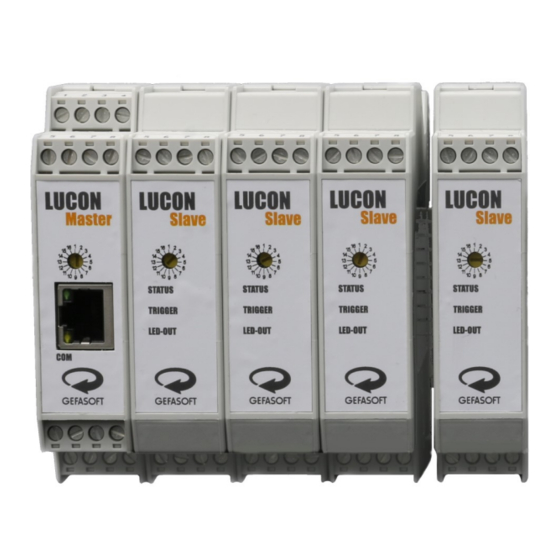
Page 22: Connecting The Light Controller
Figure 10: Module order The LUCON® 2 light controllers are not hot-pluggable. This means that all modules must be mounted in a voltage-free state! The power supply can only be activated once all modules have been mounted. Do not install any modules if the LUCON® 2 Master module is live! 5.2 Connecting the light controller Electric shock! -
Page 23: Configure Channel Numbers
5.3 Configure channel numbers On the front of the device (see Figure 11) there is a rotary coding switch which can be set with a slotted screwdriver. This sets the channel number. Figure 11: Configure channel numbers (marked area) To simplify troubleshooting or maintenance, it is advisable to give the LUCON® 2 Master module the number 01. -
Page 24: Operating
6 Operating The parameters are configured either via commands (RS232 or UDP, see chapter 6.2) or via the integrated configuration website (see chapter 6.4.3). The commands are downward compatible with the LUCON® 2 Master and LUCON® 2 Slave of the first generation. -
Page 25: Control Modes
Control modes In principle, two control modes are available: • Command-based operation: The LUCON® 2 Master module is connected to a control system (e.g. PC or PLC) via a communication interface (RS232 or network). Commands are used to switch the lighting on the various channels on and off, change their brightness or switch between operating modes. - Page 26 1000 Pulse current (A) Figure 12: Pulse length as a function of pulse current The maximum possible pulse length (in seconds) can be determined from the following equation (I = current in A): 0,002 Figure 13 provides an overview of the necessary cooling time. 10000 1000 20 A...
-
Page 27: Temporal Peculiarities In Current Control
Temporal peculiarities in current control Internally, the LUCON® 2 light controllers have different measuring ranges to achieve the highest possible precision in current control. Due to circuitry reasons, there are differences in the times required until the current is regulated. Figure 14 shows the relationship between current and delay time graphically. -
Page 28: Communication Interfaces
6.3 Communication interfaces RS232 Type Serial interface Protocol RS232 Baud rate 57600 bps Databits Equality None Stopbits Flow control None Figure 15: RS232 pin assignment on the 9-pin Sub-D connector Ethernet Type Ethernet interface (RJ45) 10.0.30.2 Subnet 255.255.255.0 Protocol Port 50 000 When using the network interface, make sure that both the light controller and the remote station (e.g. -
Page 29: Parameterisation
6.4 Parameterisation The LUCON® 2 light controllers can be configured and operated with a variety of parameters and settings. The parameters can be set using commands (see chapter 6.4.2) or using the integrated web interface (see chapter 6.4.3). An overview of all possible parameters is provided in chapter 6.4.2.2 and chapter 6.4.2.3. - Page 30 6.4.3.2) (xx stands for the desired current in mA). Then some voltages have to be determined: • The supply voltage VSUPPLY (Supply-Voltage, R01USU), • the voltage across the illumination VLED (Voltage over LED, R01UL) • and the voltage at the cathode of the lighting VIN (LED input voltage, R01ULI). The values can also be conveniently displayed in the web interface (see chapter 6.4.3.2).
-
Page 31: Parameterisation Via Commands
Parameterisation via commands Basically, all settings and parameters are initially only stored in the temporary memory. This means that they are lost after a restart (power failure or software restart). The configuration must also be stored in the permanent memory (commands: S00S, S01S, ...). - Page 32 Command overview communication module (address: 00) 6.4.2.2 SET-command Command Description Example Set current in continuous mode on several S00MCM|01,60|04,120 output modules; syntax of the values is: (Set channel 01 to 60mA and |"channel", "current value"|"channel", "current channel 04 to 120mA) value"...
- Page 33 READ command Example / Response Command Describtion (without delimiter) Debug output status R00DB Response e.g.: 'RS232,1+4+8' Firmware version R00F Response e.g.: '1.0.2' IP address R00IP Response e.g. '192.168.123.10' Subnetmask R00SM Response e.g. '255.255.255.0' UDP-port R00UDP Response: '50000‘ MAC address R00MAC Response e.g.: '54:10:EC:9A:A7:11' Serial number R00SN...
- Page 34 Command overview power module (address: 01 to 16) 6.4.2.3 SET command Command Description Example Continuous mode (software mode) S01MC|10.9 Set current value (mA) in continuous mode. For S01MC|1230 current values <= 50 mA, input to 1/10 mA is possible (e.g. 45.4 mA). Max.: 3000 mA Switch mode S01MT|4500...
- Page 35 Activate/deactivate output trigger S01O|0 (0 = output trigger disabled, S01O|1 1 = output trigger enabled) Set output trigger polarity S01OTE|R (0 or R = output trigger should rise, S01OTE|0 1 or F = output trigger should fall) S01OTE|F Set output trigger source S01OTS|0 (0 = input trigger, 2 = activate lighting) S01OTS|1...
- Page 36 READ command Example / Response Command Describtion (without delimiter) Temperature (°C) of the channel R01T Response e.g.: '45' Firmware version R01F Response e.g.: '1.0.2' Current value (mA) R01C Response syntax: "Actual", "Target" (only useful in Response e.g. '49|50' continuous mode) Pulse current (mA) R01PC Response the set value for the current in pulse mode.
- Page 37 Voltage at the cathode of the illumination (mV) R01ULI Response e.g.: '2000' Voltage at the anode of the lighting (mV) R01ULO Response e.g.: '36000' Input trigger polarity (for pulse mode) R01I 0 = pulses when trigger rises, Response e.g.: '0' 1 = pulses when trigger falls, 2 = pulses when trigger rises or falls).
-
Page 38: Parameterisation Via Configuration Website
Parameterisation via configuration website In addition to configuration via commands, the LUCON® 2 Master module offers the possibility of parameterising the light controller via a web interface. The prerequisite for this is the use of the Ethernet interface (see chapter 6.3.2). To access the web interface, the IP address of the LUCON®... - Page 39 Network configuration 6.4.3.1 The network settings are only adopted after a restart of the LUCON® 2 Master module. However, the temporary parameters ("Save temporary") are deleted again after a restart. Figure 18: LUCON® 2 network configuration (1) In the upper section of this page there are also links to sub-pages. There it is possible to save the network configuration to a file ("Save") and to restore it from a file ("Restore").
- Page 40 Channel configuration 6.4.3.2 In the main menu on the left, the channels can be configured under the item "Channels". First, the main page of the channels appears with sliders for the current outputs (see Figure 20, the respective channels must be configured for use). In addition, configuration files for all channels can be created and restored here.
- Page 41 The main configuration of the channel is done under the "Configuration" tab (see Figure 22). Figure 22: Channel configuration Furthermore, there are the tabs "Save", "Restore", "Restart" and "Factory Settings". Here you can create and restore individual configuration files for each channel, restart the channels and restore the factory settings.
- Page 42 Module" (LUCON® 2 Master and LUCON® 2 Slave). For the communication module, the possible entries are limited to the password and the firmware file (see Figure 23). Both are available after consultation with GEFASOFT Automatisierung und Software GmbH. Figure 23: Firmware update of the communication module...
- Page 43 In the case of the power module, in addition to the password and the firmware file (both are available after consultation with GEFASOFT Automatisierung und Software GmbH), the channels are required for updating (see Figure 24). The selection can consist of one, several or all channels.
-
Page 44: Faq
5) If all channel numbers are set correctly and communication is still not possible after restarting all devices, please contact GEFASOFT Automatisierung und Software GmbH for further assistance. Can I damage my LUCON® controller if the output polarity is wrong? No, the LUCON®... - Page 45 Too high an input voltage, on the other hand, can permanently damage the LUCON® 2 LED light controller. However, the LUCON® 2 may have to be sent to GEFASOFT Automatisierung und Software GmbH for repair, as the protective circuit can be permanently destroyed to prevent serious damage.
- Page 46 If all parameters are correct, it could be that the light controller is in the cooling time after a pulse (see chapter 6.2.3). During this time, trigger signals are ignored, otherwise damage to the light controller could occur. Page 46 from 48...
- Page 47 8 Technical data LUCON® 2 Master LUCON® 2 Slave Article number 00039600 00039601 Supply voltage (V 12 V to 48 V – 2) V Output voltage (V 0,7 V to (V Output current Up to 3 A continuous or up to 20 A pulsed Output current step size 0,1 mA (1,0 mA to 50,0 mA) 0,5 mA (50,5 mA to 100,0 mA)
- Page 48 If requested, GEFASOFT Automatisierung und Software GmbH can be of assistance on +49(0)941 / 788300. Page 48 from 48...
Need help?
Do you have a question about the LUCON 2 Master and is the answer not in the manual?
Questions and answers