Advertisement
Quick Links
Advertisement

Summary of Contents for Freizeitausrustung Koralewski VANDBAR
- Page 1 VANDBAR User- and Installation Manual EN Revision: R0.0...
- Page 2 Manufacturer and Service Freizeitausrüstung Koralewski Stefan Koralewski Thälmannstrasse 14 16348 Wandlitz Germany Contact Fon: 0049 33397 682918 Web: vandbar.com Email: mail@vandbar.com Service For any inquiries, please submit the serial number (see left bar hold) VANDBAR - User- and Installation Manual...
-
Page 3: Table Of Contents
4 Parts list 8 – 10 5 Safety information 11 – 16 6 Installation manual 17 – 39 7 User manual 8 Sport exercises 41 – 44 9 Maintenance 45 – 47 10 Disposal VANDBAR - User- and Installation Manual... -
Page 4: Purpose Of Use
Purpose of use VANDBR is an adjustable training-rack for sport exercises with one’s own body weight. VANDBAR shall only be used for it’s purpose of use. VANDBAR is not a cable pull station and for indoor use only. Use classes S, H and I acc. to EN ISO 20957-1:2014-05. - Page 5 - Smartphone- / Tablet-stand: Stainless steel (1.4301) and nappa synthetic leather (Option) Max. load: 120 kg Tested acc.: EN ISO 20957-1:2014-05 by TUEV SUED Purpose: Adjustable training-rack for sport exercises with one’s own body weight VANDBAR - User- and Installation Manual...
- Page 6 Product details VANDBAR *Illustration shows additional options backpanel with smartphone- / tablet-stand VANDBAR - User- and Installation Manual...
-
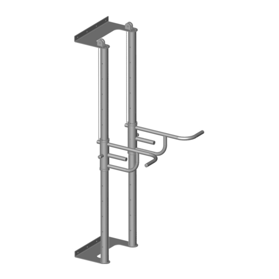
Page 7: Product Overview
Product overview VANDBAR Head plate Steel wire Steel wire holder Bottom plate Sliding tube Bar hold Lock hole Lock target Lock stud Handle screw VANDBAR - User- and Installation Manual... - Page 8 Concrete screw incl. peg and washer (8x) Bar hold (2x) M5x12 Countersunk screw (42x) M6x12 Setscrew (2x) Counterweight with steelwire (2x) Felt pad (4x) Slide bearing (4x) Coil spring (4x) Press block (2x) Pulley (2x) Wire holder inlets (2x) VANDBAR - User- and Installation Manual...
-
Page 9: Parts List
Parts list (Options) VANDBAR Smartphone- / Tablet-stand Backpanel VANDBAR - User- and Installation Manual... - Page 10 Allen wrench 3 mm (1x) Allen wrench 4 mm (1x) Allen wrench Torx TX25 (1x) Weicon Anti-Seize-Paste (1x) Abrasive fabric block (1x) M10-100 Lock screw incl. nut and plastic washer (2x) ..this User- and Installation Manual VANDBAR - User- and Installation Manual...
- Page 11 VANDBAR Important information in general Read this manual carefully before installation. Store this manual close at hand. The use of VANDBAR by children, must be observed by adults. Packaging materials must be disposed properly. VANDBAR - User- and Installation Manual...
- Page 12 Be aware, that there are neodym magnets installed inside the lock stud and lock traget. - Lock stud: 4x neodym magnets Ø6x12 - Lock target: 2x neodym magnets Ø6x12 In case you have a pacemaker, please seek medical advice bevor use. VANDBAR - User- and Installation Manual...
- Page 13 Safety information VANDBAR Important information regarding installation For installation, assure a minimum clearance of 2 m radius from the midpoint of the bar holds. VANDBAR - User- and Installation Manual...
- Page 14 / or plumber. VANDBAR must be installed inside, if installed outside, any warranty claims expire. An installation must be on a brick, concrete or solid wooden wall. A minimum load of 0,21 kN per peg and screw is needed (0,21 kN is equivalent of one Fischer concrete screw SXRL 10 x 100 FUS A4 in autoclaved cellular concrete at 70 mm minimum depth).
- Page 15 VANDBAR shall only be used by one person at the time. If VANDBAR is not in use, both bar holds should be placed at the most upper position incl. inserted lock stud. Do not tighten handle screw when not in use.
- Page 16 Inside the sliding tubes, there are counterweights. A free sliding of the counterweights inside the sliding tubes must be enabled at all times. VANDBAR is not a cable pull station. The counterweights inside the sliding tubes only function as counterbalance to keep the bar holds in position to find a locking position.
- Page 17 In case of an installation on wooden walls, the min. wall thickness must be 15 cm (wood screw‘s min. 8 x Ø 8mm and length 120 mm*) *not within the scope of supply VANDBAR - User- and Installation Manual...
- Page 18 Ø Check if the fixed felt pads (4x) on bottom plate are still in place. Attention: Did you check for any power lines or water pipes in the drilling area for bottom and head plate (see also page 26)? VANDBAR - User- and Installation Manual...
- Page 19 6 mm and re-drill with concrete drill 10 mm for pegs (minimum drilling depth 110 mm) Ø Place peg into drilling holes and fully hammer in pegs Ø Clean area from any drilling dust by vacuum cleaner VANDBAR - User- and Installation Manual...
- Page 20 Ø Position sliding tube 1 on floor cover Ø Align sliding tube 1 in a way, that the smaller inside tubes face 6 and 12 o‘clock as well as the lock holes 3 and 9 o‘clock VANDBAR - User- and Installation Manual...
- Page 21 Attention: Please position and mount with two persons to aviod any damages and scratches. Ø Tighten M5x12 countersunk screws only by hand, but hand-tighten twice clockwise Ø M5x12 countersunk screws will be loosen again at a later stage VANDBAR - User- and Installation Manual...
- Page 22 Attention: Please position and mount with two persons to aviod any damages and scratches. Ø Tighten M5x12 countersunk screws only by hand, but hand-tighten twice clockwise Ø M5x12 countersunk screws will be loosen again at a later stage VANDBAR - User- and Installation Manual...
- Page 23 Ø In contrast to the head plate, screws at the bottom plate will not be loosen again Installation step 10 – Position VANDBAR Ø Erect VANDBAR with two persons Ø The second person need to hold and secure VANDBAR from falling over Attention: Remove floor cover from underneath the bottom plate.
-
Page 24: Installation Manual
Ø Mount bottom plate with 4x concrete screws incl. plastic washer and cover cap thread Ø Insert 4x concrete screws Ø Do not fully tighten concrete screws Attention: Concrete screws at bottom plate will be loosen again with optional backpanel. VANDBAR - User- and Installation Manual... - Page 25 Installation manual VANDBAR Installation step 12 – Align VANDBAR at head plate Ø Use water level to align and mark drilling holes at head plate Attention: Did you check for any power lines or water pipes in the drilling area? Installation step 13 –...
- Page 26 Ø Insert pressblock in bar holds from above Attention: The grove in the press block must face up Ø Slide press block in hole Attention: Pressblock needs to be completely pushed in, if not possible screw out handel screw VANDBAR - User- and Installation Manual...
- Page 27 Ø Bar hold can be inter-fixed with handle screw Ø Position both bars holds near bottom plate Attention: Remove any dust from bottom plate before carefully position bar holds near bottom plate VANDBAR - User- and Installation Manual...
- Page 28 Ø Install M10-100 lock screw incl. nut and plastic washer Ø Choose second lock hole from top of the sliding tube Ø Only hand tighten nut Attention: Place 2x plastic washer left and right of the sliding tube VANDBAR - User- and Installation Manual...
- Page 29 Ø Put in 2x coil spring into Ø7 mm holes Ø Place second slide bearing into opposite groove of the counterweight Attention: Hold slide bearings into position with two hands, the second person should position the step-ladder VANDBAR - User- and Installation Manual...
- Page 30 Ø Lock screws need to be in position and tighten by hand Installation step 20 – Installation counterweights Ø Carefully insert counterweights into top of sliding tubes Ø Steel wire need to face to wall VANDBAR - User- and Installation Manual...
- Page 31 Installation step 22 - Mount head plate to sliding tubes Ø Mount head plate to sliding tube flanges with 8x M5x12 countersunk screw each Ø Torque M5x12 countersunk screws (4,5 kN) twice clockwise on each flange VANDBAR - User- and Installation Manual...
- Page 32 In case, the option backpanel will be installed, do not insert the remaining concrete screws and tighten any concrete screws Ø Insert and tighten all concrete screws on head- and bottom plate VANDBAR - User- and Installation Manual...
- Page 33 Ø Insert fixed studs from pulley into dedicated holes in head plate Ø Slightly loose M6 countersunk at pulleys Ø Insert steel wires through head plate holes and position steel wire into pulley groove VANDBAR - User- and Installation Manual...
- Page 34 Installation manual VANDBAR Ø Tighten M5x12 countersunk screws (4,5 kN) from underneath head plate Ø Tighten M6 countersunk screws (6,5 kN) at pulleys on both sides VANDBAR - User- and Installation Manual...
- Page 35 Ø Push up both bar holds approx. 150 mm Ø Inter-fix bar holds with handle screw Ø Insert steel wire into steel wire holder Ø Insert wire holder inlets Attention: Mind the small washer to be in place, when removing protection tape VANDBAR - User- and Installation Manual...
- Page 36 Ø Carefully loosen bars holds with handle screw Attention: Hold tight bar hold when lowering down Ø Steel wires must have slight tension Attention : Bar holds are balenced by counterweight inside sliding tubes VANDBAR - User- and Installation Manual...
- Page 37 Is the steel wire under slight tension? If YES – proceed! Ø Loosen nuts and remove M10-100 lock screws Ø Check if all concrete screws are tighten Ø Install all cover caps at head- and bottom plate Attention : Left-hand thread VANDBAR - User- and Installation Manual...
- Page 38 Ø Install smartphone- / tablet-stand on backpanel Attention: Check that the smartphone- / tablet-stand is orientated right in the upper part of the backpanel Ø Install 3x M5 countersunk screws from backside of the backpanel VANDBAR - User- and Installation Manual...
- Page 39 Ø Remove all concrete screws on head and bottom plate Ø Pull off VANDBAR from wall Attention: The second person must secure VANDBAR at all times, while not conneted to the wall by screws Ø Align the backpanel between wall and VANDBAR Ø...
- Page 40 Ø Only tighten with one hand, little movement will remain Ø Loosen handle screw with two hands to find a position Ø Before training start, check always the locking and handle screw Ø Bar holds can now be used separately for training VANDBAR - User- and Installation Manual...
- Page 41 Sport exercises VANDBAR Use of VANDBAR VANDBAR is designed to perform sport exercises with one’s own body weight. Many variants to train are possible for example: 1. Pull-up (Figure 1) Figure 1 2. Dips (Figure 2) 3. Push-up (Figure 3) Both bar holds can be used separately for training.
-
Page 42: Sport Exercises
Important to note: When performing a pull-up, the practitioner's hands must tightly encircle the bar holds. Your back should be straight and your view directed forward. If pain occurs in the hands, arms, joints, etc., the exercise must be stopped. VANDBAR - User- and Installation Manual... - Page 43 Important to note: When performing a dip, the practitioner's hands must firmly encircle the bar holds. Your back should be straight and your view directed forward. If pain occurs in the hands, arms and joints, etc., the exercise must be stopped. VANDBAR - User- and Installation Manual...
- Page 44 Your back should be in a straight line with your legs and your view should be directed downwards. If pain occurs in the hands, arms and joints, etc., the exercise must be stopped. VANDBAR - User- and Installation Manual...
- Page 45 Otherwise there will be undesirable changes in the surface. In no case should circular grinding be used. In case of daily use, it is recommended to carry out annual maintenance. If VANDBAR is used less than once a day, maintenance is only required every two years.
- Page 46 To check the pulleys, the bar holds must be moved up or down, while the pulleys are to be observed by a second person. The pulleys must turn silently. If this is not the case, please do not use the device and contact VANDBAR service. VANDBAR - User- and Installation Manual...
- Page 47 Inside the bar hold bearing shells, there are ten plain bearings in each of the bearing shells. The plain bearings are beige in color. If the plain bearings are worn out and no longer visible, maintenance should be ordered with VANDBAR service. VANDBAR - User- and Installation Manual...
-
Page 48: Disposal
All packaging materials should be sent to a recycling system in accordance with the applicable waste and disposal code. If you decide to dispose VANDBAR itself, we recommend that you do this with a recycling service provider for scrap metal. - Page 49 VANDBAR VANDBAR - User- and Installation Manual...
Need help?
Do you have a question about the VANDBAR and is the answer not in the manual?
Questions and answers