Table of Contents
Advertisement
Quick Links
Advertisement
Table of Contents

Summary of Contents for Cube Sense V3
- Page 1 CubeSense V3 An integrated sun and nadir sensor module User Manual...
-
Page 2: Table Of Contents
Part: CubeSense V3 Doc: User Manual Ver: 1.11 Page: Table of Contents Document Approved By ......................2 List of Acronyms/Abbreviations ..................... 2 Introduction ........................3 Getting Started ......................4 Unpacking the CubeSense package ....................4 Before getting started .......................... 4 Ground Support Program (GSP)....................... -
Page 3: Document Approved By
Part: CubeSense V3 Doc: User Manual Ver: 1.11 Page: Document Approved By Document Approved By Document CubeSense V3 User Manual Version 1.11 Date Modified 6 January 2020 Approved By: Douw Steyn Signature List of Acronyms/Abbreviations CMOS Complementary metal-oxide semiconductor ADCS Attitude and Determination Control System FPGA Field Programmable Gate Array... -
Page 4: Introduction
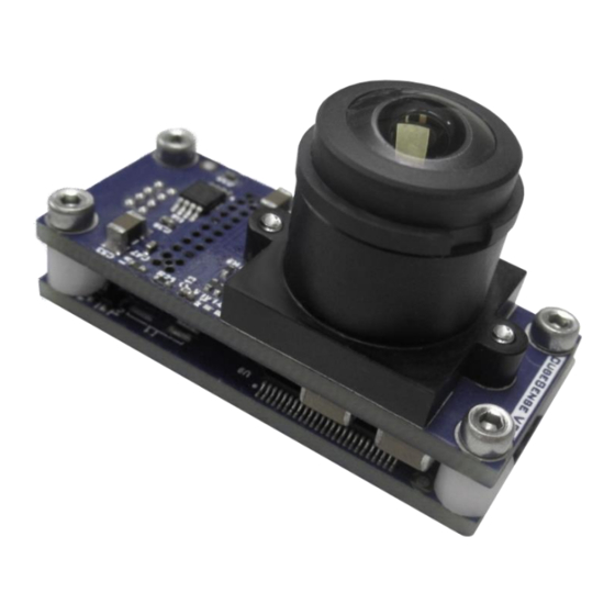
Part: CubeSense V3 Doc: User Manual Ver: 1.11 Page: 1. Introduction The CubeSense module is an integrated sun or nadir sensor for CubeSat attitude sensing. It makes use of a CMOS camera that is configured for either sun sensing or for horizon detection. If configured as a sun sensor, a neutral density filter is included in the optics to ensure that only the sun will be visible in the image. -
Page 5: Getting Started
Part: CubeSense V3 Doc: User Manual Ver: 1.11 Page: 2. Getting Started The Getting Started guide will show the simple steps to get CubeSense up and running. CubeSense is provided with a simple test application to allow the user to gain experience with the available functions as well as test the hardware. - Page 6 Part: CubeSense V3 Doc: User Manual Ver: 1.11 Page: After a couple of minutes, a message indicating the successful installation of the drivers • should appear. Browse to the folder containing the GSP and launch the application by running • CubeSenseV3_GSP_TestingApplication.exe.
-
Page 7: Hardware Setup
Part: CubeSense V3 Doc: User Manual Ver: 1.11 Page: 2.4 Hardware setup Figure 1 – CubeSense electrical connections 2.4.1 Power The CubeSense module draws its power from the USB port if the Support PCB is used. If the module is not used with the Support PCB, the power could also be provided by a stable lab power supply with a 3.3V output. - Page 8 Part: CubeSense V3 Doc: User Manual Ver: 1.11 Page: For the ground tests: Plug the CubeSense module into the support PCB (header is marked as CubeStar) • Plug the supplied UART-to-USB cable into the support PCB (the header is labelled as •...
-
Page 9: Usage
Part: CubeSense V3 Doc: User Manual Ver: 1.11 Page: 3. Usage 3.1 Identification Each CubeSense module is programmed with a serial number, and details about its firmware. To check these details about a CubeSense module, TLM no 0 and 1 can be requested. The TLMs starts at address 128, so these addresses will be 128 and 129. -
Page 10: Managing Memory Contents
Part: CubeSense V3 Doc: User Manual Ver: 1.11 Page: Byte 6-7: Bytes 6-7 forms an unsigned 16-bit integer that indicates the elapsed time since the previous second, in milliseconds. Table 3 – Serial number TLM Telemetry frame ID Name Serial number Frame length (bytes) Channels... -
Page 11: Doing Detection
Part: CubeSense V3 Doc: User Manual Ver: 1.11 Page: contents that were stored in that position. It is the user’s responsibility to choose the correct part of the SRAM to write to and to avoid overwriting data that should be stored for use at a later stage. - Page 12 Part: CubeSense V3 Doc: User Manual Ver: 1.11 Page: 5 = SRAM overcurrent Detection Unsigned 0 = start-up result 8-bit 1 = no detection scheduled 2 = detection pending 3 = Nadir error – too many detected edges 4 = Nadir error – not enough detected edges 5 = Nadir error –...
-
Page 13: Interpreting Detection Result
Part: CubeSense V3 Doc: User Manual Ver: 1.11 Page: 3.4 Interpreting detection result The sensor’s axes are defined as follows: Figure 3 – Camera axes definitions The measured angles (��, ��) that the sensor output are virtual angles that can be transformed to angles or vectors that can be used in the satellite attitude determination. -
Page 14: Capturing And Downloading Images
Part: CubeSense V3 Doc: User Manual Ver: 1.11 Page: 3.5 Capturing and downloading images CubeSense provides the option of downloading an image that is located in any of the SRAM locations. This can be done for images of the earth or of space, or to verify the exposure settings of the sensor to tweak its performance. - Page 15 Part: CubeSense V3 Doc: User Manual Ver: 1.11 Page: Fields Offset Length Field Data type Detail SRAM Unsigned 8- 0 = Top location 1 = Bot Size Unsigned 8- 0 = 1024x1024 (8192 selection frames) 1 = 512x512 (2048 frames) 2 = 256x256 (512 frames) 3 = 128 x 128 (128...
-
Page 16: Typical Use
Part: CubeSense V3 Doc: User Manual Ver: 1.11 Page: Telecommand ID Name Advance image download Parameters length (bytes) Fields Offset Length Field Data type Detail Next frame Unsigned Number of next frame to number 16-bit be loaded After this TC has been sent, TLM 65 can once more be polled until the ‘frame number’-channel is equal to the appropriate image frame. - Page 17 Part: CubeSense V3 Doc: User Manual Ver: 1.11 Page: Figure 5 – Flow diagram for typical use...
-
Page 18: Important Usage Considerations
Part: CubeSense V3 Doc: User Manual Ver: 1.11 Page: 4. Important Usage Considerations 4.1 Detection thresholding Sun/Nadir-sensors need to differentiate the sun/earth from the background of space in the images that they take. In both cases this is done by comparing the brightness of the pixels in the image to each other, in order to locate the sun and the edges of the earth. -
Page 19: Sram Over-Current Protection
Part: CubeSense V3 Doc: User Manual Ver: 1.11 Page: 4.3 SRAM over-current protection When high energy radiation causes a latch-up inside the SRAM, it will result in a high current draw that may permanently damage the SRAM. CubeSense is fitted with a current sensor to monitor the SRAM. - Page 20 Part: CubeSense V3 Doc: User Manual Ver: 1.11 Page: maximum X and Y pixel values. These two coordinates define the masking square. Take great care to ensure correct placement of these masking squares. Testing should also be performed to verify correct masking. See the Node Definition for correct telemetry and telecommands to perform masking.
- Page 21 Part: CubeSense V3 Doc: User Manual Ver: 1.11 Page: Figure 8 – ACP image transformation...
-
Page 22: Documentation History
Part: CubeSense V3 Doc: User Manual Ver: 1.11 Page: 5. Documentation History Version Author Pages Date Description of Change 15/02/2016 First draft 29/05/2016 Some updates GJVV 02/08/2016 Template and formatting update 05/08/2016 Updated for new software 1.4-1.6 19/01/2017 Various corrections 08/02/2017 Shifted various info to the ICD 11/03/2019...
Need help?
Do you have a question about the Sense V3 and is the answer not in the manual?
Questions and answers