
Summary of Contents for JORESTECH E-IND-35
- Page 1 JORESTECH MANUAL INDUCTION SEALING MACHINE ® E-IND-35/100HA/130HC OPERATIONS MANUAL READ ALL INSTRUCTIONS CONTAINED IN THIS MANUAL PRIOR TO MACHINE INSTALLATION...
-
Page 2: Table Of Contents
TABLE OF CONTENTS GENERAL INFORMATION GENERAL SAFETY WARNINGS SPECIFICATIONS OPERATION Sealing Head Selection Sequence of Operation Control Panel MAINTENANCE Routine Inspection and Servicing TROUBLESHOOTING MACHINE PARTS AND DIAGRAMS Machine Breakdown Sealing Head Breakdown Sealing Heads Dimensions and types ADITIONAL INFORMATION Understanding Induction Sealing Understanding The Results of Induction Sealing Cap &... -
Page 3: General Information
HANDLING The JORESTECH Manual Induction Sealing Machine was completely tested and inspected before ® being ready for shipment. Like any piece of electronic equipment, it should not be dropped or given harsh treatment. -
Page 4: Specifications
SPECIFICATIONS PARAMETERS E-IND-35 E-IND-100HA E-IND-130HC Rated Voltage 120VAC 120VAC 220VAC Rated Frequency 60Hz 60Hz 50/60Hz Output Power 500W (0.67HP) 500W (0.67HP) 500W (0.67HP) Sealing Time Range 0.1 – 9.9 sec 0.1 – 9.9 sec 0.1 – 9.9 sec Sealing Diameter 15–35mm (0.6-1.4”) -
Page 5: Sequence Of Operation
NOTE: Timer can be set between 0.1 and 9.9 seconds. To ensure the best seal, unit should be tested to determine the best time setting according with product. When the voltage value, shown on display is above 140VAC or below 90VAC (For E-IND-35/100HA) stop sealing work until voltage returns to normal conditions. -
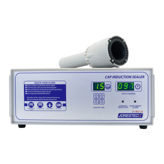
Page 6: Control Panel
IMPORTANT: DO NOT Reach into the equipment, or any electrical enclosure, without first removing the power. Always disconnect power before servicing, changing accessories or cleaning the unit. JORESTECH Manual Induction Sealing Machines are designed to require minimal maintenance. ® However, to ensure long-term reliability, it is a good practice to perform some preventive maintenance actions. -
Page 7: Troubleshooting
TROUBLESHOOTING MALFUNCTION POSSIBLE CAUSE SOLUTION Power cord is not plug in into Plug in the power cable. wall receptacle. Machine does not turn ON Fuse broken. Replace the broken fuse. Main switch damage or broken. Replace Main power switch. Control Panel is lit but nothing Broken Start button Replace Start Button happens when start button is... -
Page 8: Machine Parts And Diagrams
MACHINE PARTS AND DIAGRAMS Machine Breakdown Part Number Description Quantity Machine Top Cover Power plug Power Fuse Main Switch Induction Head Cable Gland Back Cover Display Board Front Cover Control Transformer Bridge Rectifier Control Inductive Reactance Main PCB Board Power Transistor / Cooling Fan Mounting Plate Machine Base... -
Page 9: Sealing Head Breakdown
Sealing Head Breakdown Part Number Description Quantity Cover Plate Isolation board Induction Coil Isolation Board (E-IND-130C only) Induction Coil (E-IND-130C only) Handheld Outer Cover Handheld Top Cover Induction Start Switch 10/11 Induction Head Cable Gland... -
Page 10: Sealing Heads Dimensions And Types
Sealing Heads Dimensions and types... -
Page 11: Aditional Information
ADITIONAL INFORMATION Understanding Induction Sealing Multiple Layer Liners A multiple layer liner typically consists of a pulp board layer (A), a wax layer (B), and a layer of aluminum foil (C) coated with a polymer (D). The polymer (D) must be compatible with your container material and capable of producing the seal strength and removal force required by your application. -
Page 12: Understanding The Results Of Induction Sealing
Understanding The Results of Induction Sealing Easy-Peel Liners Easy-peel liners seal tightly to the lip of the container, but allow for a clean peel from the container. Tamper-Evident Liners Tamper-evident liners seal tightly to the lip of the container, but leave part of the liner on the lip when opened. - Page 13 No Seal A No Seal result on a container is when the container is run through a sealing cycle and the liner shows no signs of adhesion to the lip of the container. Possible Causes Insufficient cycle time. Incorrect induction liner - Incompatibility. Sealer not running.
- Page 14 Deformations on the land area. Thin or weak land area – too narrow. Solutions Increase the TIMER setting on the sealer. Check cap/liner specifications to ensure the correct liner is being used. Check container specifications. Verify the torque requirement of your container and closure. Verify the proper alignment of the sealing head and your container during the sealing process.
-
Page 15: Cap & Container Issues
Cap & Container Issues Good Container Lip/Liner Contact Good contact between the liner material and the container lip is very important. This goes hand in hand with the amount of torque applied, but can be a problem even when the torque levels are good. - Page 16 Cocked Cap A cocked cap is usually due to a problem with the capping process or a cap or container problem. The gap created can cause overheating and the cap itself may actually jam the container under the sealing heads causing the liner to overheat severely. Torque Issues One of the most common causes of poor or inconsistent sealing is an improperly torqued cap.
- Page 17 700 Sawgrass Corporate Parkway, Sunrise, Fl, 33325 Phone: 305.594.9000 • Fax: 305.594.9004...
Need help?
Do you have a question about the E-IND-35 and is the answer not in the manual?
Questions and answers