Table of Contents
Advertisement
Advertisement
Table of Contents

Summary of Contents for Tecnosens NCL Series
- Page 1 Assembly Instructions for Use Free and Total Chlorine Sensors NCL and NCT model PLEASE READ CAREFULLY THE FOLLOWING INSTRUCTIONS FOR USE. DO NOT THROW THEM AWAY. THE SYSTEM MANAGER WILL BE RESPONSIBLE FOR ANY DAMAGE CAUSED BY INSTALLATION OR MANAGEMENT ERRORS. 20TMN0001B (EN) 05/2021...
- Page 2 , 25 RANCESCO NTOLISEI 00173 R TALY +39 06 4576 3210 www.tsens.biz info@tsens.eu...
-
Page 3: Table Of Contents
NDEX INTRODUCTION .....................1 ................3 ATERIALS CONTAINED IN THE SET ..................5 TRUCTURE OF THE SENSOR INSTALLATION .......................6 ................ 6 SSEMBLY ISASSEMBLY OF THE CAP ............6 ILLING THE CAP WITH ELECTROLYTIC SOLUTION ..............8 INFORMATION ON THE ELECTROLYTE GEL ................ -
Page 5: Introduction
1. Introduction NTRODUCTION This assembly and use manual describes the technical data and functions of the sensors of the NCL and NCT range, for the measurement of Free Chlorine and Total Chlorine. The characteristics of the different sensors are shown in Table 1 below, where it is indicated which is the measured analyte, the measurement range, the resolution and the type of electrical output, for the different sensors, to which this manual can be applied. - Page 6 1. Introduction Tab 1: Characteristics of the different sensors to which this manual is applicable Name Analyte Measurement Resolution[ppm] Output range [ppm] NCL T20 Free Chlorine 0.05 ÷ 20.00 0.01 0 ÷ -2000 mV NCL T10 Free Chlorine 0.05 ÷ 10.00 0.01 0 ÷...
-
Page 7: Aterials Contained In The Set
1. Introduction 1.1 M ATERIALS CONTAINED IN THE SET The device is supplied in its packaging and is presented as shown in Figure 1 and in Figure 2, in which the standard kit consists of: I. sensor; IV. bottle of gel electrolyte (100ml); II. - Page 8 1. Introduction Figure 2: version with voltage output standard supply...
-
Page 9: Structure Of The Sensor
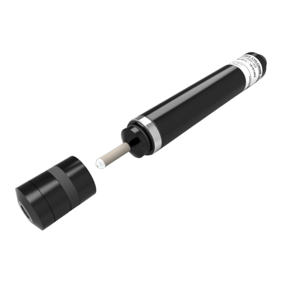
1. Introduction 1.2 S TRUCTURE OF THE SENSOR The parts composing the sensor are shown in Figure 3. Position Description Sensor body Connector Counter electrode Reference Electrode Working electrode O-Ring Membrane Tubular gasket Figure 3: Sensor structure and description of its components. -
Page 10: Installation
2. Installation NSTALLATION 2.1 A SSEMBLY ISASSEMBLY OF THE CAP Before proceeding with the assembly/disassembly operation of the cap from the probe body, the tubular gasket must be moved from its position on the cap. Pay attention that the vent hole, highlighted in Figure 4 and the other holes present, remain uncovered throughout the assembly phase. - Page 11 2. Installation Figure 5: Assembly phase of the cap Figure 4: Cap filling phase with gel electrolyte. on the probe. SLOWLY SCREW THE PROBE CAP To ensure the correct functioning of the probe, it is necessary to avoid that the air bubbles remain trapped inside the gel solution in the cap. For this reason, it is useful to slowly screw the cap to the probe, and not to shake the bottle before use.
-
Page 12: Information On The Electrolyte Gel
2. Installation DO NOT TOUCH THE CAP AND ELECTRODES Do not touch the membrane on the cap, nor the electrodes placed in the lower part of the sensor; do not damage them and avoid that they come into contact with greasy substances. Otherwise, the sensor will no longer function accurately. -
Page 13: Ounting On The Probe Holder
2. Installation WARNING RISK DUE TO A DANGEROUS SUBSTANCE When using hazardous substances, please note that updated safety data sheets of the manufacturers of these substances are available. Since the risk potential of a substance can be re-evaluated at any time based on new knowledge, the safety data sheet must be checked regularly and replaced if necessary. -
Page 14: Flow Adjustment
2. Installation NSTALLATION NSTRUCTION ✓ Make sure that the membrane does not come into contact with other objects to avoid damage and obstruction of the membrane. ✓ Once the probe has been positioned on the probe holder, it is recommended to slowly open the delivery cock to protect the membrane from the pressure front produced by the water flow. - Page 15 2. Installation Figure 6: installation of the probe in a probe holder, where the optimal operating distance is shown...
-
Page 16: Electrical Connections
3. Electrical Connections LECTRICAL ONNECTIONS 3.1 E LECTRICAL INSTALLATION OF VOLTAGE OUTPUT The probe equipped with the electric voltage output (0 ÷ −2000 mV) is provided with a circular connector. It is essential, to connect the probe to the measuring instrument, to use the dedicated electric cable (see paragraph 5.1 page 21 to identify the code) to be purchased separately. - Page 17 3. Electrical Connections Figure 7: Electrical connection of cables to the measuring instrument Table 2: Characteristics of electrical connections Terminal Color Function Value Green Signal (V 0 ÷ -2000 mVdc Yellow Signal (GND) Brown Power supply (+V +10 ÷ +30 Vdc White Power supply (GND) Single Power Supply...
-
Page 18: Lectrical Installation Of Current Output
3. Electrical Connections 3.2 E LECTRICAL INSTALLATION OF CURRENT OUTPUT Below is reported the procedure for the electrical installation of the probes equipped with the current output with two-wire connection, as shown in Figure 1. Rotate the upper element (3) of the sensor counterclockwise and extract the upper element. - Page 19 4. Activation and Maintenance of the Sensor Figure 8: Electrical installation for probes with two-wire current output...
-
Page 20: Activation And Maintenance Of The Sensor
4. Activation and Maintenance of the Sensor CTIVATION AND MAINTENANCE OF THE SENSOR 4.1 S ENSOR OMMISSIONING Once the sensor has been mounted on the probe holder and checked the correct working conditions, such as the probe insertion height, the control water flow rate and the pressure, and the connection to the electrical measuring system has been made, the activation times of the probe are those shown in Table 3. - Page 21 4. Activation and Maintenance of the Sensor The frequency of checks depends on the installation requirements and working conditions. Calibration allows you to align the value obtained with the DPD-1 method with the measured value of the probe, depending on the characteristics of the controlled water H VALUE The calibration of the probe and instrument set must be carried out at a...
-
Page 22: Lectrode Nit And Ap Aintenance
4. Activation and Maintenance of the Sensor 4.3 E LECTRODE NIT AND AINTENANCE If the values measured by the probe are abnormal (or excessively low, to the point of not allowing correct calibration or excessively high), the probe must be removed from the system and the following operations must be performed: •... - Page 23 4. Activation and Maintenance of the Sensor Figure 9: Working electrode before and after cleaning Figure 10: Cleaning the working electrode Figure 11: Do not use abrasive paper on the with abrasive paper membrane...
-
Page 24: Ut The Robe Out Of Ervice
NSTALLATION NSTRUCTIONS Observe the regulations and legal dispositions currently in force for disposal. NSTALLATION NSTRUCTIONS TECNOSENS s.r.l. takes delivery only of sensors suitably separated from contaminating chemical elements to proceed with disposal. -
Page 25: Orking Arameters And Ensor Haracteristics
4. Activation and Maintenance of the Sensor 4.5 W ORKING ARAMETERS AND ENSOR HARACTERISTICS ✓ Correspondence of output signal in voltage depending on the full scale: for example the probe with full scale at 20 ppm, the signal delivered will be −2000 mV therefore the correspondence will be equal to −100 mV for each ppm. -
Page 26: Troubleshooting And Spare Parts
5. Troubleshooting and Spare Parts ROUBLESHOOTING PARE ARTS 5.1 S PARE ARTS Code Description NAS0003A2 Cap for probes NCL NAS0006A0 Cap for probes NCT NSH0001A1 Gel electrolyte bottle (100ml) for NCL NSH0002A0 Gel electrolyte bottle (100ml) for NCT NAS0005A1 2 m cable for probes with voltage output 5.2 T ROUBLESHOOTING For troubleshooting, it is necessary to consider the entire measuring station. - Page 27 5. Troubleshooting and Spare Parts The following table shows the possible causes and solutions of the most common problems encountered on installations and during maintenance operations on the probes. Problem detected Possible cause Solution Connection cable faulty Replace the cable. See spare parts Check that all connectors are properly Connection cable secured.
- Page 28 5. Troubleshooting and Spare Parts Problem detected Possible cause Solution Extraction or insertion of the probe inside the probe holder without Membrane cap replacement. See spare parts having opened the bleed valve Incorrect assembly or Membrane cap replacement. See spare parts disassembly of the cap Deformed or Install a pressure regulator upstream of the...
- Page 29 5. Troubleshooting and Spare Parts Problem detected Possible cause Solution Incorrectly screwed cap, Clean the working electrode and replace the which caused water electrolyte gel. Carefully screw the cap back infiltration and/or on and reposition the tubular gasket correctly. leakage of gel It may be necessary to re-calibrate the electrolyte.
-
Page 30: Directives And Standards Observed
5. Troubleshooting and Spare Parts IRECTIVES AND TANDARDS BSERVED Reference EC directives: EMC Directive (2014/30 / EU) • • ROHS Directive (2011/65 / EU) International standards: EN 61010-1 • • EN 60335-1 • EN 60529 • EN 61326-1 NOTICE We reserve the right to make changes at any time and without notice in colors, materials, specifications and designs. -
Page 31: Notes
7. Notes OTES... - Page 32 , 25 RANCESCO NTOLISEI 00173 R TALY +39 06 4576 3210 www.tsens.biz info@tsens.eu...
Need help?
Do you have a question about the NCL Series and is the answer not in the manual?
Questions and answers