Table of Contents
Advertisement
Quick Links
REVOV Communication Unit v2
User Manual
.
Introduction
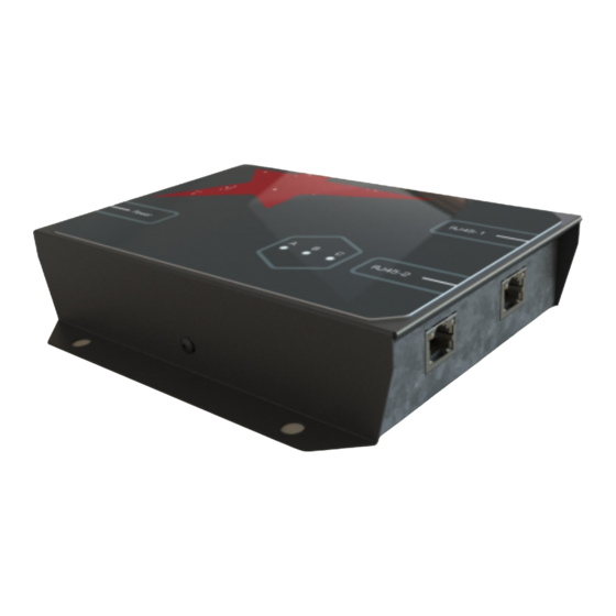
The REVOV Communication Unit v2 (RCU v2) unit enables communication between
compatible lithium battery packs and CAN bus inverters. The RCU v2 features an
RS-485 port for connection to the battery's Battery Management System (BMS) and
a CAN bus port for connection to the inverter. The RCU v2 allows the battery to
communicate directly with the inverter, allowing for the transfer of important
parameters such as current draw and battery voltage.
Rev. E (April 2021)
© REVOV 2021, under license
Page 1 of 16
Advertisement
Table of Contents

Summary of Contents for REVOV v2
- Page 1 CAN bus inverters. The RCU v2 features an RS-485 port for connection to the battery’s Battery Management System (BMS) and a CAN bus port for connection to the inverter. The RCU v2 allows the battery to communicate directly with the inverter, allowing for the transfer of important parameters such as current draw and battery voltage.
-
Page 2: Specifications
Reverse Polarity Protection Typical Maximum Current draw (24 V input) 100 mA 200 mA Current draw (48 V input) 50 mA 100 mA Depending on the selected battery mode. Rev. E (April 2021) © REVOV 2021, under license Page 2 of 16... -
Page 3: Overview Of Operation
Float voltage [V] 54.5 V As an example, if the RCU v2 is connected to a bank that contains 9 of the B100 batteries, a maximum charge current of 450A and discharge of 900A will be reported to the inverter. -
Page 4: Status Indicator Lights
Status indicator lights The RCU v2 has built-in green, yellow and red LEDs on the front surface of the enclosure. These are programmed to display the internal state of the unit: Front LEDs Status description Green Yellow No power connected. -
Page 5: Under-Voltage Shutdown
Under-voltage shutdown When the input voltage provided to the RCU v2 (typically battery voltage) drops past a certain point, the RCU v2 will turn off internal circuitry to avoid contributing further battery discharge. This protects battery against potential under-voltage damage by the RCU v2’s current draw. -
Page 6: Installation And Configuration
BMS’s RS-485 port. Ensure that this cable’s pinout is correct. 3. Plug the CAN bus communication cable into the CAN bus port of the RCU v2, and then into the CAN bus port of the inverter. If the inverter requires it, ensure that CAN bus termination is applied (typically by inserting a termination plug into an empty CAN bus port on the inverter). - Page 7 6. Wait 30 seconds for the RCU v2 to power up. On startup, the green and red LEDs will illuminate. As soon as communication is established on both the RS-485 and CAN bus ports, the red LED will switch off and the yellow LED will illuminate.
- Page 8 2. Plug the CAN bus cable into the port on the Sunsynk inverter that is labelled “DSM_CAN”. 3. The Sunsynk inverter will not automatically detect the RCU v2 if it is not set up for a lithium battery in CAN mode. To set the Sunsynk up in this way, perform the following steps on the Sunsynk’s interface:...
- Page 9 1. Ensure that the correct CAN bus cable is made up. Refer to elsewhere in this manual for the correct pinout. 2. The GoodWe inverter will not automatically detect the RCU v2 if it is not set up for the correct lithium battery. To do this: a.
- Page 10 2. Plug the CAN bus cable into the port and into the port labelled “ComSyncIn“ on the SMA inverter. 3. The SMA will not automatically detect the RCU v2 if it is not already set up for the correct lithium battery. To do this, follow these steps on the Sunny...
- Page 11 ● Revov R9 (external Tian Power BMS) The following pinouts pertain to the connection RS-485 connection between the RCU v2 and the BMS using the RJ45 RS-485 ports. A custom cable should be made - a standard straight-through Ethernet cable will not work.
- Page 12 ● SMA CAN bus port pinouts Please note that each inverter requires a custom CAN bus cable from the RCU v2 to the inverter. For example, the Victron systems use pins 7 and 8 for CAN_H and CAN_L respectively, while Sunsynk, GoodWe and SMA inverters use pins 4 and 5 for CAN_H and CAN_L.
- Page 13 Sunsynk, GoodWe & SMA CAN bus cable pinout Pin number RCU v2 Sunsynk / GoodWe/SMA CAN_H CAN_H CAN_L CAN_L CAN bus cable pinouts diagrams Victron Sunsynk GoodWe Rev. E (April 2021) © REVOV 2021, under license Page 13 of 16...
-
Page 14: Troubleshooting
Troubleshooting RCU v2 will not power on If none of the LEDs light up when power is applied to the RCU v2, it is likely that the RCU v2 is not receiving power. To remedy, attempt the following: ● Double-check the polarity of the power connection. - Page 15 No communication with BMS or inverter If the red LED on the front of the RCU v2 is illuminated, there is a communications error, either with the RS-485 link, the CAN bus, or both. To determine which is the case, look at the LEDs of the RJ45 ports on the RCU v2. An alternately flashing green and yellow light means successful communication, so look for the port with switched-off LEDs.
-
Page 16: Legal Notice
REVOV disclaims any and all liability for any damages or losses incurred by you or any third parties arising from the use of any REVOV product that is inconsistent with any REVOV data sheet, user’s manual or other REVOV documents.
Need help?
Do you have a question about the v2 and is the answer not in the manual?
Questions and answers