
Summary of Contents for ANTIFERENCE ASM02
- Page 1 ASM02 Digital Signal Meter for Satellite & Terrestrial with DSCR Mode & Data Logging User Guide...
- Page 2 Important Safety Notice Thank you for purchasing this Antiference signal analyser product. Please read the following instructions carefully, retain for future reference and read the following safety considerations: Do not place any items on the device Ensure no liquids are on or near the device as splashes may damage the unit...
-
Page 3: Table Of Contents
Table of Contents Page Contents Introduction Features Package Contents Front & Top Panel Layouts 4.1 Top Panel Layout 4.2 Front Panel Layout Main Menu DVB-S/S2 Mode 6.1 Measurement 6.2 Spectrum 6.3 Constellation 6.4 Dish Setup 6.5 Motor Settings 6.6 Angle Calculation 6.7 TP Control 6.8 Datalog 6.9 DSCR... -
Page 4: Introduction
1. Introduction The Antiference ASM02 is an advanced signal analyser for satellite and terrestrial signals. It features an 8.9 inch touch screen display and simple to use menu system. It supports DVB-S/S2/DVB-T/T2/DVB-C/C2, DAB/DAB+. Also included is a DSCR mode for analysis of SKY Q systems and a data logging function allowing the user to download logs to a USB drive and view in an Excel spreadsheet. -
Page 5: Package Contents
3. Package contents ASM02 Signal Meter 12V 2000mA Mains Charger with 3 Pin UK Plug 12V In-Car Charger Soft Carry Case Rubber/Plastic ASM02 Protective Jacket F Connector Adaptors 4 Point Shoulder Strap 4. Front & Top Panel Layouts 4.1. Top Panel Description... - Page 6 4. Front & Top Panel Layouts (cont) 4.2. Front Panel Description Green LED. When lit, indicates 13V is enabled in DVB-S/S2 mode Green LED. When lit, indicates 18V is enabled in DVB-S/S2 mode Green LED. When lit, indicates 22KHz tone is enabled in DVB-S/S2 mode Green LED.
-
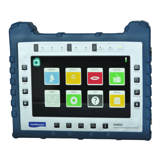
Page 7: Main Menu
5. Main Menu When the ASM02 has booted, the main menu will appear. To navigate to the sub-menu’s, simply tap the icon of the mode you wish to operate and the menu for that function will appear. To return to the previous menu, press [EXIT] 6. -
Page 8: Measurement
6. DVB-S/S2 Mode 6.1. Measurement Menu (cont) Explanation of Functions in DVB-S/S2 Mode Tap the [BACK] icon to return to the main menu Tap the [SPECTRUM] icon to enter spectrum mode Tap the [CONSTELLATION] icon to enter constellation mode Tap the [DISH SETUP] icon to enter the dish setup menu Tap the [ANGLE SETTING] icon to view the angle calculation menu Tap the [TRANSPONDER] icon to enter the transponder control menu Tap the [ZOOM] icon to enter the zoom menu... - Page 9 6. DVB-S/S2 Mode 6.1. Measurement Menu (cont) Explanation of Elements - Modulation error ratio value - Link margin test results CBER - CBER test results LBER - LBER test results Pilot Pattern - The pilot pattern of signal value Orbit Position - The orbit position of the TS in the NIT table TS Bit rate - The bit rate of the input TS...
-
Page 10: Spectrum
6. DVB-S/S2 Mode 6.2. Spectrum The ASM02 can display live spectrum from 950MHz to 2150MHz covering legacy satellite analysis and limited wideband frequencies. Functions in Spectrum Mode • Tap the spectrum chart to see more detail including the centre of the frequency and power level •... -
Page 11: Constellation
6. DVB-S/S2 Mode 6.3. Constellation This menu shows the constellation chart of the live stream. The transponder list is shown on the left hand side of the screen. Touch a transponder in the list to switch to it. Explanation of Elements Power level - The power level of the input signal Astra 2... -
Page 12: Dish Setup
6. DVB-S/S2 Mode 6.4. Dish Setup The dish setup menu allows the manual configuration of various parameters including LNB type, power, tone & switch type. Explanation of Elements LNB Type - Tap desired value to set. The edit pop up window allows the setting of the local oscillator value if required - Tap to adjust the 22KHz tone status LNB Power... -
Page 13: Motor Settings
6. DVB-S/S2 Mode 6.5. Motor Settings The motor setting menu allows changes to be made to a motorised satellite system. A dish can be controlled in this menu as part of the set up process. Explanation of Elements 67.3 dBµV - The power level of the input signal DVBS QPSK 5/6 - DVB type, demodulation type &... - Page 14 6. DVB-S/S2 Mode 6.5. Motor Settings (cont) DiSEqC Command Buttons Tap to send MOVE TO EAST command Tap to send MOVE TO WEST command Tap to send STOP MOVING command Tap to set the east limit command Tap to send the west limit command Tap to send the DISABLE LIMITATION command Tap to centre the dish position Tap to send command to saved position...
-
Page 15: Angle Calculation
6.6. Angle Calculation This menu calculates the azimuth & elevation of the satellite dish via the current satellite settings and local position. The ASM02 can monitor the alignment process helping the user to get the dish in the correct position. -
Page 16: Tp Control
6. DVB-S/S2 Mode 6.7. TP Control Within the transponder (TP) control menu, more detail can be seen on each transponder being received. This includes the frequencies, MER, signal strength & quality in percentages. In this menu it is possible to create and download a data log of the signals being received by transponder. - Page 17 6. DVB-S/S2 Mode 6.8. TP Control (cont) The transponder list can be edited in this menu manually. The top list of transponders are already available in the TP control menu. The bottom list are the rest of the transponders which are not currently available in the TP control menu. Tap an item to add it to the TP control menu.
- Page 18 6. DVB-S/S2 Mode 6.9. Datalogging The ASM02 can save a datalog via the TP control menu. This can be done from the DVB-S mode or DVB-T mode, See page 15 (DVB-S) or page 23 (DVB-T) to view how this process is started. Once the datalog has been saved, this data can be downloaded to a USB drive.
- Page 19 6. DVB-S/S2 Mode 6.10. DSCR Mode The ASM02 is pre-programmed with the UK DSCR user bands for analysis of DSCR systems. To access this menu, navigate to the DVB-S/S2>dish setup>switch type menu (shown below) and select the user band required.
-
Page 20: Dvb-T/T2 Mode
7. DVB-T/T2 Mode 7.1. Measurement From the main menu, tap the DVB-T/T2 icon to enter the terrestrial measurement menu. This menu shows all the analysis of the incoming terrestrial signal. The incoming terrestrial frequencies are listed on the left hand side of the screen and the measurement details on the right. - Page 21 7. DVB-T/T2 Mode 7.1. Measurement (cont) Explanation of Elements - Modulation error ratio value CBER - CBER test results LBER - LBER test results Feed Current - The feed current of the RF input load Feed Voltage - The feed voltage of the RF input load ONID - The Original Network ID of the input transport stream TSID...
-
Page 22: Spectrum
7. DVB-T/T2 Mode 7.2. Spectrum The terrestrial spectrum can scan from 100MHz to 900MHz to show live analysis of the incoming signal. Functions in Spectrum Mode • Tap the spectrum chart to see more detail including the detail of frequency and power level •... -
Page 23: Constellation
7. DVB-T/T2 Mode 7.3. Constellation The constellation menu shows the live transport stream on a constellation chart. the multiplex frequencies are shown on the left hand side of the screen with the detail on the middle and the constellation chart on the right. Tap a frequency to see details. Explanation of Elements Power level - The power level of the input signal... -
Page 24: Scope
7. DVB-T/T2 Mode 7.4. Scope The scope menu shows signal lock and the various multiplex incoming signals. This menu shows power level, MER plus signal strength and quality in percentages. Tap the mux you want to view on the left hand side. Tap this icon to edit the multiplex list for this menu See page 24. -
Page 25: Datalog
7. DVB-T/T2 Mode 7.5. Datalog The multiplex list can be edited in this menu manually. The top list of multiplexes are already available in the scope menu. The bottom list are the rest of the multiplexes which are not currently available in the scope menu. Tap an item to add it to the scope menu. -
Page 26: Dvb-C Mode
8. DVB-C Mode 8.1. Measurement From the main menu, tap the DVB-C icon to enter the cable TV measurement menu. This menu shows all the analysis of the incoming cable TV signal. The incoming frequencies are listed on the left hand side of the screen and the measurement details on the right. - Page 27 8. DVB-C Mode 8.1. Measurement (cont) Explanation of Elements - Modulation error ratio value CBER - CBER test results LBER - LBER test results ONID - The Original Network ID of the input transport stream TSID - The Transport Stream identification of the input stream TS Bit rate - The bit rate of the incoming transport stream Frequency Offset...
-
Page 28: Spectrum
8. DVB-C Mode 8.2. Spectrum The cable spectrum can scan from 100MHz to 900MHz to show live analysis of the incoming signal. Functions in Spectrum Mode • Tap the spectrum chart to see more detail including the detail of frequency and power level •... -
Page 29: Constellation
8. DVB-C Mode 8.3. Constellation The constellation menu shows the live transport stream on a constellation chart. the channel frequencies are shown on the left hand side of the screen with the detail on the middle and the constellation chart on the right. Tap a frequency to see details. Explanation of Elements Power level - The power level of the input signal... -
Page 30: Scope
8. DVB-C Mode 8.4. Scope The scope menu shows signal lock and the various incoming signals. This menu shows power level, MER plus signal strength and quality in percentages. Tap the mux you want to view on the left hand side. Tap this icon to edit the multiplex list for this menu See page 24. -
Page 31: Datalog
8. DVB-C Mode 8.5. Datalog The frequency list can be edited in this menu manually. The top list of frequencies are already available in the scope menu. The bottom list are the rest of the frequencies which are not currently available in the scope menu. Tap an item to add it to the scope menu. -
Page 32: Dab/Dab
9. DAB/DAB+ Mode The ASM02 can analyse DAB & DAB+ signals via the DAB menu. From the main menu, tap the DAB/DAB+ tile to navigate to the measurement menu. Functions in DAB/DAB+ Mode • Tap the RESCAN button to re-start a scan on all frequency channels •... -
Page 33: Diseqe Monitor
10. DiSEqC Monitor This menu for DiSEqC monitoring can detect DiSEqC commands on the LNB input of the meter. This can be used to fault find DiSEqC issues from another meter or set-top box. -
Page 34: Settings
11. System Settings General Settings & Parameters This menu allows the adjustment of general meter settings such as volume, brightness, attenuation etc and shows the current software version of the device. 12. Help From the main menu, tap the ‘help’ button to access this user guide... -
Page 35: Memory
13. Memory From the main menu, tap the ‘memory’ button to access the saved screenshots of the meter. From this menu, it is possible to edit the name of the screenshot, delete or copy to USB. 14. LNB/RF Overload If an LNB or RF overload appears, a dialogue box will appear informing of the short or overload. - Page 36 15. Channel Scan & View From the measurement screen in any mode, click to perform a channel scan. Scan options include single channel, all channels or blind scan. The screen below will appear while the scan is carried out. Once the scan is complete, the video can be viewed as below. Information on the channel is shown on the info bar below the video.
-
Page 37: Technical Specifications
16. Technical Specifications DVB-S/S2 Identification DVB-S2 DVB-S 250MHz ~ 2300MHz Frequency Rage Demodulation QPSK QPSK, 8QPSK Code Rate 1/2, 2/3, 3/4, 5/6, 7/8, 1/4, 1/3, 2/5, 1/2, 3/5, 2/3, 3/4, 5/6, 8/9, 9/10, Symbol Rate 2~45MSPS Input Impedance 75Ω Min.level in 35dBuV(noise)... - Page 38 16. Technical Specifications...
-
Page 39: Declaration Of Conformity
17. Declaration of Conformity We, ANTIFERENCE LIMITED herewith declare that the HDMI extender kit complies with all essential requirements and any other applicable conditions set forth on directive 2014/30/EU. According to the WEEE (Waste Electrical and Electronic Equipment) EU Directive, do not dispose of this product as household waste or commercial waste.
Need help?
Do you have a question about the ASM02 and is the answer not in the manual?
Questions and answers