
Subscribe to Our Youtube Channel
Related Manuals for ACS contsys MIR-491

Summary of Contents for ACS contsys MIR-491
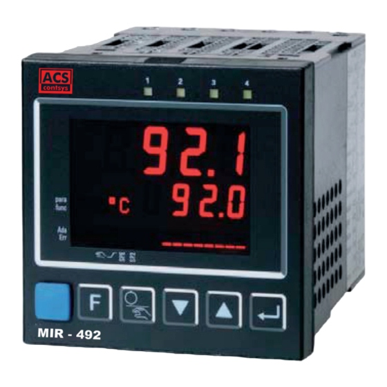
- Page 1 Operating Instructions MIR-491 and MIR-492 Industrial- and process controller MIR-491 MIR-492...
- Page 2 û û BlueControl BlueControl More efficiency in engineering, More efficiency in engineering, more overview in operating: more overview in operating: ® ® The projecting environment for the BluePort The projecting environment for the BluePort controllers controllers Description of symbols Description of symbols in the text: in the text: on the device:...
-
Page 3: Table Of Contents
Contents Mounting ......5 Electrical connections ..... . . 6 Connecting diagram . - Page 4 Switching attitude linear ( CyCl= 1 ) ... . . 45 4.4.2 Switching attitude non-linear ( CyCl= 2 ) ..46 4.4.3 Heating and cooling with constant period ( CyCl= 3 ) .
-
Page 5: Mounting
Mounting Mounting Mounting Mounting MIR-491 MIR-492 +0,8 +0,8 min.48 min.48 (1.89") (1.89") 920. 1 920. 1 921. 2 921. 2 para para func func 1199 1199 1199 1199 +0,6 +0,6 1200 1200 °C °C °C °C 1200 1200 °F °F °F... -
Page 6: Electrical Connections
Electrical connections Electrical connections 2.1 Connecting diagram 90...250V 24 V UC OUT1 INP2 OUT2 INP3 MIR-49x-1...-1... KS90-1..-.1... 100% OUT3 (mV) MIR-49x-1.4... KS90-1. - 4 ... MIR-49x-1.5... KS90-1. - 5 ... Volt INP1 OUT4 (16) MIR-49x-1.2... KS90-1. - (mV) +24V DC OUT5 OUT6 24V GND... -
Page 7: Terminal Connection
Electrical connections 2.2 Terminal connection Power supply connection 1 See chapter "Technical data" Connection of outputs OUT1/2 2 OUT1/2 heating/cooling Relay outputs (250V/2A), potential-free changeover contact Connection of outputs OUT3/4 3 a relay (250V/2A), potential-free changeover contact universal output b current (0/4...20mA) voltage (0/2...10V) d transmitter supply logic (0..20mA / 0..12V) - Page 8 Electrical connections Connection of inputs di2/3 8 (option) Digital inputs (24VDC external), galvanically isolated, configurable as switch or push-button 9 (option) Connection of output U Supply voltage connection for external energization Connection of outputs OUT5/6 0 (option) Digital outputs (opto-coupler), galvanic isolated, common positive control volta- ge, output rating: 18...32VDC Connection of bus interface ! (option) PROFIBUS DP or RS422/485 interface with Modbus RTU protocol...
- Page 9 Electrical connections 3 OUT3 transmitter supply 22mA (16) 9 RS485 interface (with RS232-RS485 interface converter) * RGND RGND RGND R = 120...200 Ohm DATA B DATA B DATA B (16) (16) (16) DATA A DATA A DATA A R=100 Ohm RS485-RS232 converter max.
- Page 10 Electrical connections Electrical connections 3 OUT3 as logic output with solid-state relay (series and parallel connection) 3 OUT3 as logic output with solid-state relay (series and parallel connection) Series connection Series connection Parallel connection Parallel connection I =22mA I =22mA I =22mA I =22mA Logic...
-
Page 11: Operation
Operation Operation 3.1 Front view 1199 920. 1 1200 °C °F para 921. 2 func para func SP.E SP.2 § " & § " & 1 Statuses of switching outputs OuT. 1 ... 6 2 Process value display 3 Setpoint or correcting variable display 4 °C or °F display signalling 5 Signals ConF- and PArA level 6 Signals activated function key... -
Page 12: Behaviour After Power-On
Operation 3.2 Behaviour after power-on After supply voltage switch-on, the unit starts with the operating level. The unit is in the condition which was active before power-off. If the controller was in manual mode at supply voltage switch-off, the controller will re-start with the last output value in manual mode at power-on. -
Page 13: Error List / Maintenance Manager
Operation 3.4 Error list / Maintenance manager With one or several errors, the extended operating le- 1199 vel always starts with the error list. Signalling an ac- tual entry in the error list (alarm, error) is done by the 1200 °C °F Err LED in the display. - Page 14 Operation Cause Possible remedial action Name Description Heating current - Current flow in heating - Check heating current circuit short circuit circuit with controller off - If necessary, replace solid-state relay (SSR) - SSR defective Control loop - Input signal defective or not - Check heating or cooling circuit LooP alarm (LOOP)
- Page 15 Operation Self-tuning heating ( ADA. H ) and cooling ( ADA. C ) error status: Description Behaviour Error status No error Faulty control Re-configure controller (inverse i direct) action No response of The control loop is perhaps not closed: check sensor, process variable connections and process Low reversal point...
-
Page 16: Self-Tuning
Operation 3.5 Self-tuning For determination of optimum process parameters, self-tuning is possible. After starting by the operator, the controller makes an adaptation attempt, where- by the process characteristics are used to calculate the parameters for fast line-out to the set-point without overshoot. The following parameters are optimized when self-tuning: Parameter set 1: - Proportional band 1 (heating) in engineering units [e.g. -
Page 17: Optimization After Start-Up Or At The Set-Point
Operation 3.5.2 Optimization after start-up or at the set-point The two methods are optimization after start-up and at the set-point. As control parameters are always optimal only for a limited process range, vari- ous methods can be selected dependent of requirements. If the process behaviour is very different after start-up and directly at the set-point, parameter sets 1 and 2 can be optimized using different methods. -
Page 18: Step Attempt After Start-Up
Operation 3.5.4 Step attempt after start-up - tunE = 0 and sufficient set-point reserve provided Condition: - tunE = 2 The controller outputs 0% correcting variable or Y. L o and waits, until the process is at rest (see start-conditions on page 8). Subsequently, a correcting variable step change to 100% is output. - Page 19 Operation Optimization-at-the-set-point procedure: The controller uses its instantaneous parameters for control to the set-point. In li- ned out condition, the controller makes a pulse attempt. This pulse reduces the correcting variable by max. 20% 1, to generate a slight process value unders- hoot.
-
Page 20: Optimization At The Set-Point For 3-Point Stepping Controller
Operation 3.5.7 Optimization at the set-point for 3-point stepping controller With 3-point stepping controllers, the pulse attempt can be made with or without position feedback. Unless feedback is provided, the controller calculates the mo- tor actuator position internally by varying an integrator with the adjusted actuator travel time. -
Page 21: Self-Tuning Start
Operation 3.5.8 Self-tuning start Start condition: w For process evaluation, a stable condition is required. Therefore, the controller waits until the process has reached a stable condition after self-tuning start. The rest condition is considered being reached, when the process value oscillation is smaller than ±... -
Page 22: Acknowledgement Procedures In Case Of Unsuccessful Self-Tuning
Operation 3.5.10 Acknowledgement procedures in case of unsuccessful self-tuning 1. Press keys Ù and È simultaneously: The controller continues controlling using the old parameters in automatic mode. The Err LED continues blinking, until the self-tuning error was acknowledged in the error list. 2. -
Page 23: Examples For Self-Tuning Attempts
Operation 3.5.11 Examples for self-tuning attempts (controller inverse, heating or heating/cooling) Start: heating power switched on Heating power Y is switched off (1). When the change of process value X was constant during one minute (2), 100% the power is switched on (3). At the reversal point, the self-tuning at- Start r t reversal point... -
Page 24: Manual Self-Tuning
Operation 3.6 Manual self-tuning The optimization aid can be used with units on which the control parameters shall be set without self-tuning. For this, the response of process variable x after a step change of correcting va- riable y can be used. Frequently, plotting the complete response curve (0 to 100%) is not possible, because the process must be kept within defined limits. -
Page 25: Second Pid Parameter Set
Operation Parameter adjustment effects Parameter Control Line-out of Start-up behaviour disturbances Pb1 higher increased damping slower line-out slower reduction of duty cycle lower reduced damping faster line-out faster reduction of duty cycle td1 higher reduced damping faster response to faster reduction of duty cycle disturbances lower increased damping... -
Page 26: Alarm Handling
Operation 3.8 Alarm handling Max. three alarms can be configured and assigned to the individual outputs. Ge- nerally, outputs OuT. 1 ... OuT. 6 can be used each for alarm signalling. If more than one signal is linked to one output the signals are OR linked. Each of the 3 li- mit values Lim. - Page 27 Operation The variable to be monitored can be selected seperately for each alarm via configuration The following variables can be monitored: w process value w control deviation xw (process value - set-point) w control deviation xw + suppression after start-up or set-point change After switching on or set-point changing, the alarm output is suppressed, until the process value is within the limits for the first time.
-
Page 28: Operating Structure
Operation 3.9 Operating structure After supply voltage switch-on, the controller starts with the operating levels. The controller status is as before power off. 1199 1199 Ù PASS Ù PArA 1200 para 3 sec. 1199 Ù PASS ConF Ì para 1199 Ù... -
Page 29: Configuration Level
Configuration level Configuration level 4.1 Configuration survey ConF Configuration level SP. F n I. F nc I. F nc I. F nc Fnc. 1 bAud O. A ct O. t YP O. t YP È C. t YP StYP StYP S. L in Src. 1 SP. -
Page 30: Configuration Parameters
Configuration level 4.2 Configuration parameters Cntr Name Value range Description Default SP. F n Basic configuration of setpoint processing set-point controller can be switched over to external set-point (-> LOGI/ SP. E ) standard controller with external offset (SP. E ) C. - Page 31 Configuration level Name Value range Description Default FAIL Behaviour at sensor break controller outputs switched off y = Y2 y = mean output. The maximum permissible output can be adjusted with parameter Ym. H . To prevent determination of inadmissible values, mean value formation is only if the control deviation is lower than parameter L.
- Page 32 Configuration level Name Value range Description Default thermocouple type S (0...1760°C), PtRh-Pt10% thermocouple type R (0...1760°C), PtRh-Pt13% thermocouple type T (-200...400°C), Cu-CuNi thermocouple type C (0...2315°C), W5%Re-W26%Re thermocouple type D (0...2315°C), W3%Re-W25%Re thermocouple type E (-100...1000°C), NiCr-CuNi thermocouple type B (0/100...1820°C), PtRh-Pt6% special thermocouple Pt100 (-200.0 ...
- Page 33 Configuration level InP. 2 Name Value range Description Default I. F nc Function selection of INP2 no function (subsequent input data are skipped) heating current input external set-point (SP. E ) Yp input Second process value X2 External positioning value Y.E (switch-over r LOGI / Y. E ) no controller input (e.g.
- Page 34 Configuration level Name Value range Description Default S. L in Linearization (onlyatS. t YP=30(0..20mA)and40(0..10V)adjustable) none Linearization to specification. Creation of linearization table with BlueControl (engineering tool) possible. The characteristic for KTY 11-6 temperature sensors is preset. S. t YP Sensor type selection thermocouple type L (-100...900°C) , Fe-CuNi DIN thermocouple type J (-100...1200°C) , Fe-CuNi thermocouple type K (-100...1350°C), NiCr-Ni...
- Page 35 Configuration level Name Value range Description Default Fnc. 1 Function of limit 1/2/3 switched off Fnc. 2 measured value monitoring Fnc. 3 Measured value monitoring + alarm latch. A latched limit value can be reset via error list or via a digital input, or by pressing key Ò...
- Page 36 Configuration level Name Value range Description Default OFF...9999 Operating hours (only visible with BlueControl Hour â OFF...9999 Output switching cycles (only visible with BlueControl Swit â Out. 1 and Out. 2 Name Value range Description Default O. A ct Method of operation of output OUT1 direct / normally open inverse / normally closed Y.
- Page 37 Configuration level Out. 3 Out4 Name Value range Description Default O. t YP Signal type selection OUT3 relay / logic (only visible with current/logic voltage) 0 ... 20 mA continuous (only visible with current/logic/voltage) 4 ... 20 mA continuous (only visible with current/logic/voltage) 0...10 V continuous (only visible with current/logic/voltage) 2...10 V continuous (only visible with current/logic/voltage) transmitter supply (only visible without OPTION)
- Page 38 Configuration level Name Value range Description Default HC. A L Heating current alarm signal (only visible when O.TYP=0) not active active HC. S C Solid state relay (SSR) short circuit signal (only visible when O.TYP=0) not active active FAi. 1 INP1/ INP2 / INP3 error (only visible when O.TYP=0) FAi.
- Page 39 Configuration level Name Value range Description Default SP. E Switching to external setpoint SP. E no function (switch-over via interface is possible) always active DI1 switches DI2 switches (only visible with OPTION) DI3 switches (only visible with OPTION) è - key switches Y/Y2 switching no function (switch-over via interface is possible) DI1 switches...
- Page 40 Configuration level Name Value range Description Default Err. r Reset of all error list entries no function (switch-over via interface is possible) DI1 switches DI2 switches (only visible with OPTION) DI3 switches (only visible with OPTION) è - key switches Ò...
- Page 41 Configuration level Name Value range Description Default dP. A D 0...126 Profibus address bc. u p Behaviour as backup controller (see page ) No backup functionality With backup functionality Entering parameter for O in ppm or % Parameter for O -function in ppm Parameter for O -function in %...
- Page 42 Configuration level Name Value range Description Default Block extended operating level (only visible with BlueControl!) IExo Released Blocked Suppression error storage (visible only with BlueControl !) 0 ILat ® No: error message remain in the error list until acknowledgement. alarms are deleted from the error list as soon as corrected OFF...9999 Password (only visible with BlueControl!)
- Page 43 Configuration level Name Value range Description Default In. 2 -999.0..99999 Input value 2 1150 The signal is in [µV] or in [[] dependent of input type Ou. 2 0,001...9999 Output value 2 -38,94 Signal assigned to In. 2 In. 1 6 -999.0..99999 Input value 16 4470 The signal is in [µV] or in [[] dependent of input type Ou.
-
Page 44: Set-Point Processing
Configuration level 4.3 Set-point processing The set-point processing structure is shown in the following picture: 1199 Xeff °C 1200 °F Internal para func set-point SP.E SP.2 Ü SP. H i SP. L o External Limitation Ü Effektive SP. E set-point Ö... -
Page 45: Switching Behaviuor
Configuration level 4.4 Switching behaviuor With these controllers, configuration parameter CYCL (ConF/ Cntr/ CYCL) can be used for matching the cycle time of 2-point and 3-point controllers. This can be done using the following 4 methods. 4.4.1 Standard ( CyCl= 0 ) The adjusted cycle times t1 and t2 are valid for 50% or -50% correcting varia- ble. -
Page 46: Switching Attitude Non-Linear ( Cycl= 2 )
Configuration level 4.4.3 Switching attitude non-linear ( CyCl= 2 ) With this method, the cooling power is nor- t. o n t. o ff mally much higher than the heating power, i.e. the effect on the behaviour during tran- sition from heating to cooling may be nega- tive. -
Page 47: Heating And Cooling With Constant Period ( Cycl= 3 )
Configuration level 4.4.4 Heating and cooling with constant period ( CyCl= 3 ) 1 and t2 are met in the overall output range . To prevent unreasonably short t1 t2 pulses, parameter tp is used for adju- sting the shortest pulse duration. With small correcting values which require a pulse shorter than the value adjusted in tp, this pulse is suppressed. -
Page 48: Configuration Examples
Configuration level 4.5 Configuration examples 4.5.1 On-Off controller / Signaller (inverse) SP. L O SP. H i InL. 1 InH. 1 InP. 1 Ê 100% Out. 1 Â ConF / Cntr: SP. F n set-point controller C. F nc signaller with one output C. -
Page 49: 2-Point Controller (Inverse)
Configuration level 4.5.2 2-point controller (inverse) SP. L O SP. H i InL. 1 InH. 1 InP. 1 Ê 100% Out. 1 Â ConF / Cntr: SP. F n = 0 set-point controller C. F nc = 1 2-point controller (PID) C. -
Page 50: 3-Point Controller (Relay & Relay)
Configuration level 4.5.3 3-point controller (relay & relay) SP. L O SP. H i InL. 1 InH. 1 InP. 1 Ê 100% 100% Out. 1 Â Out. 2 Â ConF / Cntr: SP. F n = 0 set-point controller C. F nc = 3 3-point controller (2xPID) C. -
Page 51: 3-Point Stepping Controller (Relay & Relay)
Configuration level 4.5.4 3-point stepping controller (relay & relay) SP. L O SP. H i InL. 1 InH. 1 InP. 1 Ê 100% 100% Out. 1 Â Out. 2 Â ConF / Cntr: SP. F n = 0 set-point controller C. -
Page 52: Continuous Controller (Inverse)
Configuration level 4.5.5 Continuous controller (inverse) SP. L O SP. H i InL. 1 InH. 1 InP. 1 Ê 20 mA Out. 3 Â 0/4 mA ConF / Cntr: SP. F n = 0 set-point controller C. F nc = 1 continuous controller (PID) C. -
Page 53: D - Y - Off Controller / 2-Point Controller With Pre-Contact
Configuration level 4.5.6 D - Y - Off controller / 2-point controller with pre-contact SP. L O SP. H i InL. 1 InH. 1 InP. 1 Ê 100% Out. 1 Â Out. 2 Â d. S P ConF / Cntr: SP. -
Page 54: Continuous Controller With Position Controller
Configuration level 4.5.7 Continuous controller with position controller ( Cntr/ C. F nc = 6 ) OUT.4 Ycontinuous INP.1 Ypid Master controller OUT.1 INP.2 OUT.2 Position controller Basically, this controller function is a cascade. A slave controller with three-point stepping behaviour working with position feedback Yp as process value (INP2 or INP3) is added to a continuous controller. -
Page 55: Measured Value Output
Configuration level 4.5.8 Measured value output phys. quantity Out. 1 mA / V phys. quantity Out. 0 0/4mA 20mA 0/2V 90...250VAC 24VUC OUT3 OUT4 (16) INP1 ConF / Out. 3 / 4: O. t YP = Out. 3 / 4 0...20mA continuous Out. -
Page 56: Parameter Setting Level
Parameter setting level Parameter setting level 5.1 Parameter survey Parameter setting level PArA È Pb12 SP. L o InL. 1 Inl. 2 InL. 3 L. 1 Pb22 SP. H i OuL. 1 OuL. 2 OuL. 3 H. 1 Ì ti12 SP. 2 InH. -
Page 57: Parameters
Parameter setting level Return to the beginning of a group is by pressing the Ù key for 3 sec. If for 30 sec. no keypress is excecuted the controler returns to the process value and setpoint display ( Time Out = 30 sec. ) 5.2 Parameters Cntr Name... - Page 58 Parameter setting level PAr. 2 Name Value range Description Default Pb12 1...9999 1 Proportional band 1 (heating) in phys. dimensions (e.g. °C), 2. parameter set Pb22 1...9999 1 Proportional band 2 (cooling) in phys. dimensions (e.g. °C), 2. parameter set Ti22 0,1...9999 Integral action time 2 (cooling) [s], 2.
- Page 59 Parameter setting level Name Value range Description Default InL. 3 -1999...9999 Input value for the lower scaling point OuL. 3 -1999...9999 Displayed value for the lower scaling point InH. 3 -1999...9999 Input value for the upper scaling point OuH. 3 -1999...9999 Displayed value for the upper scaling point t.
-
Page 60: Input Scaling
Parameter setting level 5.3 Input scaling When using current, voltage or resistance signals as input variables for InP. 1 , InP. 2 or/and InP. 3 scaling of input and display values at parameter setting le- vel is required. Specification of the input value for lower and higher scaling point is in the relevant electrical unit (mA / V / W). -
Page 61: Calibration Level
Calibration level Calibration level CAL) is only visible if ConF / InP. 1 / Corr = 1 Measured value correction ( or 2 is chosen. The measured value can be matched in the calibration menu ( CAL). Two me- thods are available: Offset correction ( ConF/ InP. - Page 62 Calibration level Offset correction ( ConF/ InP. 1 / Corr =1 ): 1199 Ù PArA 1200 °C °F Ì 3 sec. para func SP.E SP.2 r Ù r r Ù Ù InP. 1 InL. 1 È r Ù OuL. 1 Ì...
- Page 63 Calibration level 2-point correction ( ConF/ InP. 1 / Corr = 2): 1199 Ù PArA °C 1200 °F para Ì 3 sec. func SP.E SP.2 ConF Ì r Ù r r Ù Ù InP. 1 InL. 1 È È InL1 Ì...
-
Page 64: Special Functions
Special functions Special functions ® 7.1 DAC – motor actuator monitoring ® (Digital Actor Control DAC With all controllers with position feedback Yp, the motor actuator can be monito- ® red for functional troubles. The DAC function can be started by chosing the pa- rameter C. - Page 65 Special functions Functioning of the DAC function No input filter should be defined for the Yp input ( PArA / InP. x / t. F x = 0 ). Therewith no wrong detection of blocking or wrong method of operation can be recognized.
-
Page 66: O 2 Measurement
Special functions 7.2 O measurement This function is available only on the instrument version with INP3. As the O -measurement result range can extend over many decades, automatic display switch-over between “ % ” and “ppm“ was realized. The instantaneous unit is displayed in the lower line. -
Page 67: Configuration
Special functions 7.2.2 Configuration: Oxygen measurement Oxygen measurement with heated lambda probe Controller r Process value processing r 7: O functions with constant probe temperature Cntr r C. t YP O2-const Oxygen measurement with non-heated lambda probe Controller r Process value processing r O functions with measured probe temperature Cntr r C. -
Page 68: Linearization
Special functions 7.3 Linearization Linearization for inputs INP1 or INP3 Access to table “ Lin” is always with selection of sensor type S.TYP = 18: special thermocouple in INP1 or INP3, or with selection of linearization S. L in 1: special linearization. Dependent of input type, the input signals are specified in µV or in Ohm dependent of input type. -
Page 69: Loop Alarm
Special functions 7.4 Loop alarm The loop alarm monitors the control loop for interruption (not with three-point stepping controller and not with signallers.) With parameter LP.AL switched to 1(= loop alarm active), an interruption of the control loop is detected, unless the process value reacts accordingly with Y=100% after elapse of 2xTi. -
Page 70: Ks9X-1 As Modbus Master
Special functions Special functions 7.6 MIR-49x als Modbus-Master 7.6 KS9x-1 as Modbus master 7.6 KS9x-1 as Modbus master This function is only selectable with BlueControl (engineering tool)! This function is only selectable with BlueControl (engineering tool)! Additions othr Additions othr (only visible with BlueControl!) (only visible with BlueControl!) Name... -
Page 71: Bluecontrol
BlueControl BlueControl BlueControl BlueControl BlueControl BlueControl BlueControl is the projection environment for the BluePort® controller series. â â â BlueControl is the projecting environment for the BluePort BlueControl is the projecting environment for the BluePort BlueControl is the projecting environment for the BluePort controller series of controller series of controller series of... -
Page 72: Versions
Versions Versions MIR-491- MIR-492- KS 90-1 Format 48 x 96 connection via flat-pin terminal .......... - Page 73 Versions Accessory equipment with ordering information Description Order no. Heating current transformer 50A AC 9404-407-50001 PC-adaptor for the front-panel interface 9407-998-00001 Standard rail adaptor 9407-998-00061 Operating manual German 9499-040-62918 Operating manual English 9499-040-62911 Operating manual French 9499-040-62932 Operating manual Russian 9499-040-62965 Interface description Modbus RTU German...
-
Page 74: Technical Data
Technical data Technical data Span start, end of span: anywhere within measuring range Scaling: selectable -1999...9999 INPUTS Linearization: 16 segments, adaptable with BlueControl PROCESS VALUE INPUT INP1 Decimal point: adjustable Input circuit monitor: 12.5% below span start (2mA, 1V) Resolution: >... - Page 75 Technical data Nominal voltage 24 V DC external Current output Current sink (IEC 1131 type 0/4...20 mA configurable. Logic “0” -3...5 V Signal range: 0...approx.22mA Logic “1” 15...30 V Max. load: £ 500 W Current requirement approx.. 5 mA Load effect: no effect Resolution: £...
- Page 76 Technical data Technical data Technical data Shock test Ea (DIN IEC 68-2-27) Shock test Ea (DIN IEC 68-2-27) Shock test Ea (DIN IEC 68-2-27) BEHAVIOUR WITH POWER FAILURE BEHAVIOUR WITH POWER FAILURE BEHAVIOUR WITH POWER FAILURE Shock: Shock: Shock: Configuration, parameters and adjusted Configuration, parameters and adjusted Configuration, parameters and adjusted Duration:...
- Page 77 Technical data Mounting Accessories delivered with the unit Panel mounting with two fixing clamps at top/ bot- Operating manual tom or right/left, high-density mounting possible Fixing clamps Mounting position: uncritical Weight: 0.27kg Table 1 Thermocouples measuring ranges Thermoelementtype Measuring range Accuracy Resolution (Ô) Fe-CuNi (DIN)
-
Page 78: Safety Hints
Safety hints Safety hints This unit was built and tested in compliance with VDE 0411-1 / EN 61010-1 and – delivered in safe condition. – complies European guideline 89/336/EWG (EMC) and is provided with CE marking. – tested before delivery and passed the tests required by test schedule. –... - Page 79 Safety hints Safety hints SHUT-DOWN SHUT-DOWN For taking the unit out of operation, disconnect it from all voltage sources and For taking the unit out of operation, disconnect it from all voltage sources and protect it against accidental operation. protect it against accidental operation. If the controller is connected with other equipment in the same signal loop, check If the controller is connected with other equipment in the same signal loop, check that other equipment in the output circuit is not affected before switch-off.
-
Page 80: Resetting To Factory Setting
Safety hints 11.1 Resetting to factory setting, or to a customer-specific data set In case of faultyconfiguration, the device can be reset to a default condition. Unless changed, this basic setting is the manufacturer-specific controller default setting. ® However, this setting may have been changed by means of the BlueControl software. - Page 81 Safety hints Safety Levels Password Instrument reaction after confirming switches ”YES” by pressing Ù 1 closed always factory reset 2 open free none Factory reset without prompt for the password 3 open free defined Factory reset after entry of the correct pass number 4 open min.
- Page 82 Current signal measuring range ..74 Index DAC ....64 - 65 2-point correction... . 61 Digital inputs di1, di2, di3 - Configuration .
- Page 83 Linearization ....68 Safety hints ... . 78 - 81 Safety switch....5 Safety test.
- Page 84 Füllstand Pegel Druck Temperatur Durchfluss Regis- Sensorik Visua- Mess- trierung lisierung umformer Wir erwarten Ihren Anruf. ACS-CONTROL-SYSTEM GmbH Lauterbachstr. 57 D- 84307 Eggenfelden Tel: +49 (0) 8721-9668-0 Fax: +49 (0) 8721-9668-30 ACS-CONTROL-SYSTEM info@acs-controlsystem.de know how mit System www.acs-controlsystem.de Ihr Partner für Messtechnik und Automation...
Need help?
Do you have a question about the MIR-491 and is the answer not in the manual?
Questions and answers