
Related Manuals for Dilo SF6


Summary of Contents for Dilo SF6
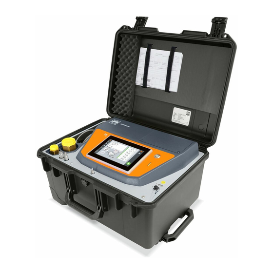
- Page 1 / CF mixing and maintenance unit Operating Manual (original version) Type-no.: Z863R01 Comm-no.: 30000400 Year of construction: 2014...
-
Page 2: Table Of Contents
In case of nonobservance of the operating instruction the manufacturer cannot assume any liability or warranty. The copyright of this documentation remains with DILO Armaturen und Anlagen GmbH, D-87727 Babenhausen. Any use not permitted by the author (multiplication, leaving to third persons etc.) is subject to penalty and indemnification. -
Page 3: General Safety Notes
SF (can be obtained from the SF supplier) is available for the operating personnel. The instructions mentioned in the data sheet and safety precautions must be known and observed by the operating personnel. www.dilo-gmbh.com 0100.bae... - Page 4 If the warning sign „Warning“, appears, there is no danger for persons. The corresponding symbol which is used cannot replace the text of the safety note. Therefore the complete text must always be read. This symbol is not for safety notes, but for information to understand the device better. www.dilo-gmbh.com 0100.bae...
- Page 5 Danger compartment connected. In case of non-observance there is the danger of implosion or explosion of the gas compartment if the device is not operated correctly. www.dilo-gmbh.com 0100.bae...
- Page 6 If a device has been contaminated with SF decomposition products additional safety measures are to be taken. Furthermore protective clothing and a dust mask depending on the degree of contamination is required. The working protection set is available under the order number: 3-442-R001. www.dilo-gmbh.com 0100.bae...
- Page 7 liquids that may have come out have been removed (wiped away) all safety devices for the unit are properly set and in working order. www.dilo-gmbh.com 0100.bae...
- Page 8 The equipment contains the greenhouse gas SF6 as stipulated in the Kyoto Protocol, with a global warming potential (GWP) of 22200. SF6 needs to be recovered and must not be released into the atmosphere. When using and handling SF6 please observe IEC 62271-4 (High-voltage Danger switchgear and controlgear –...
- Page 9 Danger caused by use of the cart for applications for which it was not intended. We recommend that all persons who are involved in the operation and repair of DILO devices are properly and specially trained. Construction and operation of the service cart...
- Page 10 The vacuum compressor is a dry-running type and is protected from inadmissible operating conditions by manostat, solenoid valve and return valves. The vacuum compressor switches on automatically during the gas recovery process. (Technical data and description see chapter 11 of the operating manuals for the vacuum compressor). www.dilo-gmbh.com 0200.bae...
- Page 11 The SF -gas is purified and dried with the particle filter and dry filter installed in the system. During each gas handling process the SF -gas passes through these filters. (see chapter 9 dry filter or particle filter) www.dilo-gmbh.com 0200.bae...
- Page 12 (if included) and the weight of the integrated bottle scales are also displayed on the operating panel. General information: All operating elements and control monitoring systems are well arranged on the front panel. All connecting lines are produced according to the well-proved DILO metal-to-metal sealing principle and are absolutely tight. www.dilo-gmbh.com 0200.bae...
- Page 13 There is a control lamp between both buttons of the double key which lights up if a function is running. Operating panel (basic configuration): Selected function Storage pressure Storage weight Screen selection “Settings“ Screen selection “Manual operation“ Gas compartment pressure www.dilo-gmbh.com 0200.bae...
- Page 14 3. Press the corresponding “F1 - F10” key until the desired digit is displayed on the screen. The desired digit is accepted after one second or immediately after having pressed another key. 4. For navigation between the digits use the arrow keys. 5. Confirm the input by pressing the <ENTER> key. www.dilo-gmbh.com 0200.bae...
- Page 15 The suction pump starts the recovery process after having reached the final vacuum of 1 Torr (difference final vacuum to hysteresis). Finally a vacuum test is carried out. If the pressure does not exceed the final vacuum the function is completed automatically. Note: the entered final vacuum must be higher than the hysteresis entered! www.dilo-gmbh.com 0200.bae...
- Page 16 Product description The running times of the components are displayed here. www.dilo-gmbh.com 0200.bae...
- Page 17 Now the components indicated on the operating panel can be switched on and off or the valves can be opened and closed by means of the corresponding function key. In order to complete the manual operation press the “down arrow“ key and select another function with the knob switch. www.dilo-gmbh.com 0200.bae...
- Page 18 Then enter the password. After entering the correct password press the <F910> key once again and the page for setting the running times of the components appears. If the password is incorrect you have to enter the password again. www.dilo-gmbh.com 0200.bae...
- Page 19 Product description The running times of the components can be modified here. Press the “up arrow” key to leave this page and to reach the storage weight page. Return to the basic configuration by pressing the “up arrow” key. www.dilo-gmbh.com 0200.bae...
-
Page 20: Dimension Sheet / Technical Data
Electrical connection: Operating voltage: 208-240V, 50/60 Hz 380-500V, 50/60 Hz Fuse protection: 32 -50 A time delay 25-32 A time delay Conductor diameter: ≥ 10 mm² (AWG 7) ≥ 6 mm² (AWG 9) Power plug: 63 A 32 A www.dilo-gmbh.com 0202.bae... -
Page 21: Transport And Installation
Service carts with chassis may only be moved on even and solid ground. The chassis is designed for a maximum speed of 6km/h. Notes for transport of DILO devices with hydraulic weighing device (not applicable for electronic weighing device) The weight must be taken off the load cell prior to transport of the device. - Page 22 The “Incorrect direction of rotation” lamp lights up if the power connection or direction of rotation is incorrect. Operation is blocked. Check the power connection or exchange the phase connections of the incoming power supply or reverse the reversing switch (if available). Attention: Disconnect the power plug beforehand! www.dilo-gmbh.com 0300.bae...
- Page 23 During the initial setting into operation and while changing the mixing ratio, the intermediate tank should be prepared with the correct mixing ratio. If not, there might occur any faults especially when mixing small gas quantities. For this purpose see chapter “Premixing of buffer tank“. www.dilo-gmbh.com 0400.bae...
- Page 24 -gas will be contaminated. For pressure tanks, which are installed by the customer observe the following: As the connecting hose is filled with air it must be evacuated after the installation, otherwise the SF gas could be contaminated. www.dilo-gmbh.com 0400.bae...
-
Page 25: Functional Description
The switches are started or stopped by pressing. In the middle there is a status indication which can output different conditions e. g. Breakdown, Run, Off, End or Lack of gas. In case of errors an additional error window with a plaintext message appears. (e. g. overpressure compressor) www.dilo-gmbh.com 0500.bae... - Page 26 But this should be avoided as divergences in the mixing ratio may occur. A tank for the final mixture is connected to the outlet coupling (pos. 103). The max. filling pressure is 40 bar (580 psig). www.dilo-gmbh.com 0500.bae...
-
Page 27: Mixing Of Sf 6 And Cf
“Filling of the buffer tank“) and refilled with the correct mixing ratio with the “Filling of buffer tank“ function. Setting of the filling pressure on the operating panel Start of the mixing function (Mix Permanent) If the set filling pressure is reached the function stops automatically. www.dilo-gmbh.com 0500.bae... - Page 28 For this purpose the described preparatory steps must be followed. It is not necessary to connect any tank for filling. The process is started by pressing the “Fill Buffer“ If the corresponding filling pressure of the buffer tank is reached, the process stops automatically. www.dilo-gmbh.com 0500.bae...
- Page 29 “Fill buffer tank” function with the correct mixing ratio. Setting of the filling pressure on the operating panel. Starting the “Mixing“ function (Mix Step). If the set filling pressure is reached the function is completed automatically. www.dilo-gmbh.com 0500.bae...
- Page 30 The buffer tank is emptied into a tank connected to the storage coupling. Procedure: Connect an appropriate tank to the ‘storage connection” or coupling pos. 103 Start the “Empty Buffer“ function on the operating panel. If the set recovery vacuum is reached the function is completed automatically. www.dilo-gmbh.com 0500.bae...
- Page 31 In the service cart the “Rinsing compressor“ special function is provided. This function can be carried out automatically via the special functions key (see chapter 6). www.dilo-gmbh.com 0500.bae...
- Page 32 Then the preselected function can be started by pressing the green “I" key. The activated function can be stopped by the red "0" key. During the “Filling of SF6" function the compressor switches on automatically if there is a certain pressure difference between storage pressure and gas compartment pressure.
-
Page 33: Evacuation Of Air From The Gas Compartment
In case the vacuum (during the holding time) is lower than the input value, the “function completed“ message appears. If the vacuum (during the holding time) exceeds the input value the “vacuum rise” message appears. Press the red “0“ key and the “function completed“ respectively the “vacuum rise” message disappears. www.dilo-gmbh.com 0500.bae... - Page 34 In case the vacuum (during the holding time) is lower than the input value, the “function completed“ message appears. If the vacuum (during the holding time) exceeds the input value the “vacuum rise” message appears. Press the red “0“ key and the “function completed“ respectively the “vacuum rise” message disappears. www.dilo-gmbh.com 0500.bae...
-
Page 35: Removal And Storage Of Sf
Warning Select the “2. Recovery of SF6” function by means of the knob switch. Start the recovery function by pressing the green “I“ key. After having reached the set final vacuum the function stops automatically and the ‘function completed’... -
Page 36: Filling The Gas Compartment With Sf 6 Gas
When reaching a certain pressure difference the compressor switches on automatically. After having reached the set final pressure the function stops automatically and the ‘function completed’ message appears. Press the red “0“ key, the “function completed“ message disappears. www.dilo-gmbh.com 0500.bae... -
Page 37: Flooding The Gas Compartment With Ambient Air
After flooding uncouple the connecting hose from the gas compartment and evacuate to < 1 mbar. (see “Evacuation of the gas compartment“). This is to avoid mixing ambient air from the connecting hose with gas later on during gas handling. www.dilo-gmbh.com 0500.bae... -
Page 38: Special Functions For Maintenance
Then the preselected function can be started by pressing the green “I" key on the double key. The activated function can be stopped by the red "0" key on the double key. The special functions stop as soon as the knob switch is turned to another position. www.dilo-gmbh.com 0600.bae... - Page 39 After about 6 minutes set the pressure on the gas compartment side to < 0 psig. by means of the filling pressure reducer pos. 181. Then the gas flows through the suction pump. The function runs for max. 10 minutes and stops automatically. But the function can also be stopped by pressing the red “0” key. www.dilo-gmbh.com 0600.bae...
- Page 40 Establish pressure compensation in the device (in manual operation see chapter 2) open all solenoid valves except pos. 133 and 132). Check the pressure (all gauges and pressure indications should display a value of < 29 psig). Close the ball valve on the SF cylinder and uncouple the storage connecting hose. www.dilo-gmbh.com 0600.bae...
- Page 41 Open the valve pos. 135 in manual operation (see chapter 2) Open the filling pressure reducer pos. 181. Open the venting ball valve pos. 201 and wait for pressure compensation. Close the venting ball valve. Close the solenoid valve pos. 135. www.dilo-gmbh.com 0600.bae...
- Page 42 Select the “7: Evacuation of filter “ function by means of the knob switch. Open the filling pressure reducer pos. 181. Start the function by pressing the green “I” key. If the filter is evacuated to the desired final vacuum (< 0.75 Torr) stop the function with the red “0” key. www.dilo-gmbh.com 0600.bae...
- Page 43 After the test reduce the pressure by opening the solenoid valve pos. 134. This is carried out in manual operation. If the indicated final pressure is not reached during the functional test the valve seats and piston rings must be checked (see operating instructions of the compressor). www.dilo-gmbh.com 0600.bae...
- Page 44 These solenoid valves can only be preselected and open as soon as the corresponding conditions are fulfilled. In case the solenoid valve pos. 137 is preselected or opened the evaporator is activated as well. For detailed information on the manual operation please see chapter 2. www.dilo-gmbh.com 0600.bae...
- Page 45 The function has to be started via the manual operation. Open all solenoid valves. Start the vacuum pump by means of the <F3> key. If the device is evacuated to the required final vacuum (< 1mbar) stop the function with the red “0“ key. www.dilo-gmbh.com 0600.bae...
- Page 46 137 and the compressor by means of the corresponding keys on the operating panel. Close the cylinder valve on the SF gas cylinder. Establish pressure compensation in the device and disconnect the gas cylinder. www.dilo-gmbh.com 0600.bae...
-
Page 47: Fault Correction
lack of gas After elimination of the cause of breakdown the “Overpressure vacuum pump“ and the “Gas lack“ error message must be reset by means of the red “0” key of the double key. www.dilo-gmbh.com 0800.bae... - Page 48 Lack of gas Storage tank is empty Check the pressure in the storage Storage pressure < 2bar tank (fill the storage tank) Ball valve on the storage tank is Check the position of the ball valve closed www.dilo-gmbh.com 0800.bae...
- Page 49 Due to excess temperature the Press in the blue button of the safety heat safety temperature limiter temperature limiter (see label in the has switched off terminal box of the evaporator) Check the temperature control of the evaporator. www.dilo-gmbh.com 0800.bae...
-
Page 50: Maintenance And Functional Test
When working with harmful materials (e. g. filter cartridge) the working Danger protection set should be used (DILO-working protection set 3-442-R...) Exchange filters which contain or are saturated with decomposition products. The operating hours of the individual components can be displayed on the operating panel (see chapter 2) When reaching a maintenance interval the maintenance is to be carried out in accordance with the maintenance schedule. - Page 51 2. The DILO-coupling tongue parts DN8 and DN20 are equipped with an O-ring which is to provide an external seal during the coupling process. As the O-ring is used for each coupling process and because of abrasion, it should be replaced from time to time.
- Page 52 Dry filter after filtering of filter cartridge or filter exchange contaminated gas, after content saturation of the filter (measurement downstream from the filter) Particle filter check during each filter cartridge exchange if necessary exchange of the dry filter www.dilo-gmbh.com 0901.bae...
- Page 53 The evaporator heating is controlled by a temperature regulating device. The solenoid valve on the input of the evaporator, which releases the gas flow, is also controlled via the temperature regulating device (The solenoid valve opens as soon as the evaporator has reached its adjusted temperature). www.dilo-gmbh.com 0902.bae...
- Page 54 1 litre (LVO100) vacuum pump oil 3-745-R201 gasket kit 6-1049-R002 3-899-R002 dry filter spare filter cartridge for dry filter 3-899-06 Partikelfilter 3-377-R001/R020 particle filter spare filter cartridge for particle filter DN20 3-377-08 L057 Spare parts kit for general parts 6-1048-R019 www.dilo-gmbh.com 0903.bae...
- Page 55 Dry filter revision 3-899-R… www.dilo-gmbh.com C 1978-03 Page 1 / 8...
- Page 56 The housing parts which are under pressure must not be worked on mechanically and welded. The type plate should not be modified, made illegilbe or removed. www.dilo-gmbh.com C 1978-03 Page 2 / 8...
- Page 57 The following gaseous decomposition products appear most frequently beside others in used SF -gas: hydrogen fluoride sulphur dioxide thionyl fluoride sulfuryl fluoride sulfur tetrafluoride With the dry filter 3-899 these gaseous decomposition products can be adsorbed. www.dilo-gmbh.com C 1978-03 Page 3 / 8...
- Page 58 SF If SF that was exposed to such an arc energy had been led over a dry filter the filter cartridge has to be exchanged. www.dilo-gmbh.com C 1978-03 Page 4 / 8...
- Page 59 Before using the filter cartridge check if the covering caps are still tight and not damaged. Only use filter cartridges which are delivered in perfect packing. Store the filter cartridges in dry rooms. Remove packing and sealing caps only short time before the installation. Scope of supply of the filter cartridge www.dilo-gmbh.com C 1978-03 Page 5 / 8...
- Page 60 Put the filter cartridge with compression spring in the screw cap as illustrated. Screw in the filtering cone until the stop. Attention: The dry filter must be evacuated before putting it into operation. www.dilo-gmbh.com C 1978-03 Page 6 / 8...
- Page 61 3-442. Please observe: The DILO-refilling device 3-834-R002 should be used for the exchange of the used desiccative (to be ordered separately). Remove the sealing caps (pos. 7).
- Page 62 -Anlagen, BGI 753 Berufsgenossenschaft der Feinmechanik und Elektrotechnik, Gustav-Heinemann-Ufer 130, Köln Conversion for SF 8.1 ppm v = 1 ppm m 1 ppm m = 1 mg/kg 1 Angström = 10 -10 m www.dilo-gmbh.com C 1978-03 Page 8 / 8...
- Page 63 Attention: The particle filter must be evacuated before putting it into operation. Attention: If the filter cartridge is left until disposal it has to be put into a plastic packing and sealed tightly. Thus the decomposition products are no longer set free. www.dilo-gmbh.com C 266-07 Page 1 / 2...
- Page 64 3-377-08 guide pipe compression spring order no. 3-377-05 o-ring 67x3 order no. 05-0057-R075 input output screw cap 5. Bibliography -Anlagen, BGI 753 Berufsgenossenschaft der Feinmechanik und Elektrotechnik, Gustav-Heinemann-Ufer 130, Köln www.dilo-gmbh.com C 266-07 Page 2 / 2...
- Page 65 / 2.0 / 2.0 / 2.0 -Q11 -Q21 -Q31 -Q51 /4.5 /5.3 /5.3 /5.3 /5.3 /3.2 /3.3 /3.3 -Q01 /3.1 Reversing I> I> I> I> I> I> I> I> I> I> I> I> /4.5 /5.3 /5.3 /5.3 /5.3 switch 1 0 2 / 2.0 Abt.
- Page 66 LAN1 power supply 3x200-240V / 9.1 Gas mixing plant -F03 -F03 -X10 -Q02 -X03 -X03 I> I> I> power supply 3x380-440V Thermistor -B01 -B11 -K51 /5.1 /5.3 -F02 phase sequence relay -F01 T01,L1 / 9.1 -S01 emerg.- S01,L1 / 4.1 T01,L2 / 3.1 -T02...
- Page 67 -Q11 -Q21 -Q31 -Q51 230V 230V 230V 230V T01,L2 T01,L2 / 4.1 Abt. Anz. / 4.1 compressor suction pump vacuum pump evaporator Betr Betr -X10 Betr Betr Betr Pos.136 Pos.135 Pos.133 Pos.132 2 /1.3 2 /1.4 2 /1.6 2 /1.8 4 /1.3 4 /1.4 4 /1.6...
- Page 68 S01,L1 S01,L1 / 9.1 / 5.0 -F11 /5.3 -Q11 /1.2 / 5.0 T01,L2 T01,L2 / 9.1 Abt. Anz. / 5.0 Betr Betr -X10 Betr Betr Betr Pos.11 Pos.131 Pos.137 Pos.134 Pos.600 Pos.601 fan for compressor Date Name Anlage control circuit diagram service cart Z863R01-01S 28.07.2014...
- Page 69 / 6.1 -Q11 /1.2 -X10 -Q21 /1.4 -Q31 /1.6 Only at option: Phasemaster -Q51 -B01 /1.7 -S04 /2.5 -F11 /4.5 BCD-Code -B11 /2.6 / 6.1 / 6.1 selection of -X10 Abt. Anz. function Betr Betr Betr Betr Pos.305 Pos.303 Betr pressure sensor pressure sensor (evaporator)
- Page 70 / 7.1 / 7.1 / 9.1 Abt. Anz. -X10 br/gr Betr Betr Betr Betr Betr Pos.302 Pos.301 Pos.304 Pos.306 Pos.151 Pos.603 Pos.604 pressure sensor vacuum sensor pressure sensor pressure sensor regulating valve pressure sensor pressure sensor Date Name Anlage control circuit diagram service cart Z863R01-01S 28.07.2014...
- Page 71 / 9.1 -S03 -S05 / 9.1 start/ stop start/ stop Abt. Anz. function evacuation at port 602 Betr Betr Betr Betr Betr Date Name Anlage control circuit diagram service cart Z863R01-01S 28.07.2014 deilt D-87727 Babenhausen Page gepr./frei Modification Date Name...
- Page 72 WE100-2 WE100-2 OPTION 3 load cells Abt. Anz. Betr Betr Betr Betr Betr sensor OPTION SF6 bottle sensor balance pressure tank K091R62 Date Name Anlage control circuit diagram service cart Z863R01-01S 28.07.2014 deilt D-87727 Babenhausen Page gepr./frei...
- Page 73 T01,L1 T01,L2 white PWR+ grey PWR- yellow brown green GNDx 2 3 5 -A01 Panel 120-240V 24VDC DI a DI b KP300 Basic output 14 digital input 24V 2 analog 4 analog input 0-10V/ 0-20mA 4 analog input 0-10V/0-20mA RS232 input 0-10V -K01 -K02...
- Page 74 I> I> / 1.1 Abt. Anz. pos. 727 Betr Betr Betr Betr Betr Evaporator LAN1 / 6.1 Service cart Datum Name Z863R01-02S 1/ 6 SF6/CF4-gas mixing plant Main circuit diagram gez. 14.10.2014 gepr. D-87727 Babenhausen Mitteil-Nr., Änderung, Tag/Name Ers. f.
- Page 75 I> -X03 T01,L2 / 3.1 / 4.1 Abt. Anz. Θ Betr Betr Betr Betr Betr / 4.1 / 2.1 Datum Name Z863R01-02S 2/ 6 SF6/CF4-gas mixing plant Main circuit diagram gez. 14.10.2014 gepr. D-87727 Babenhausen Mitteil-Nr., Änderung, Tag/Name Ers. f.
- Page 76 / 4.1 T01,L2 T01,L2 / 4.1 Abt. Anz. / 3.1 Betr Betr Betr Betr Betr Pos.607 Pos.707 Pos.708 Pos.725 Pos.741 Datum Name Z863R01-02S 3/ 6 SF6/CF4-gas mixing plant Main circuit diagram gez. 14.10.2014 gepr. D-87727 Babenhausen Mitteil-Nr., Änderung, Tag/Name Ers. f.
- Page 77 / 5.1 T01,L2 T01,L2 / 5.1 / 4.1 Abt. Anz. Betr Betr Betr Betr Betr Pos.709 Pos.710 Pos.715 Θ Pos.717 Datum Name Z863R01-02S 4/ 6 SF6/CF4-gas mixing plant Main circuit diagram gez. 14.10.2014 gepr. D-87727 Babenhausen Mitteil-Nr., Änderung, Tag/Name Ers. f.
- Page 78 Anz. Magnet- LAN2 / 6.1 ventile öffnen Betr Betr Pos.70 Betr Betr Betr Pos.728 Pos.739 gas monitoring system B169R12 Datum Name Z863R01-02S 5/ 6 SF6/CF4-gas mixing plant Main circuit diagram gez. 14.10.2014 gepr. D-87727 Babenhausen Mitteil-Nr., Änderung, Tag/Name Ers. f.
- Page 79 10 relay output 250V WAN LAN4 LAN3 LAN2 LAN1 DQ a DQ b Abt. Anz. Betr Betr Betr Betr Betr LAN2 LAN1 Datum Name Z863R01-02S 6/ 6 SF6/CF4-gas mixing plant Main circuit diagram gez. 14.10.2014 gepr. D-87727 Babenhausen Mitteil-Nr., Änderung, Tag/Name Ers. f.
- Page 80 05-0728-R005 S03, S05 Double key 24V 1S 1Ö K101R01 1 pole snap action switch 05-0467-R001 Universal transformer, WA-U 630 05-0747-R020 Power supply unit 24VDC/0,6A 05-1461-R101 Operator display WE100-2 05-1820-R002 Coupling 05-0751-R009 Power plug 05-0752-R009 Built-in socket; 1461-050 05-0753-R004 www.dilo-gmbh.com 1001-S01.bae...
- Page 81 208-240V 60 Hz Control voltage 230V Compressor: TM 5.0B 5.00 kW 19.5 A Suction pump: 15m 0.45 kW 4.25 A Vacuum pump: 40m 1.7 kW 6.6 A Evaporator: K032R01 4.80 kW 12.5 A Control: 0.50 kW 2.55 A www.dilo-gmbh.com 1001-S01.bae...
- Page 82 Connecting kit 05-1091-R002 Flip switch 1 pole 05-0467-R001 Universal transformer 05-0747-R008 Power unit 05-1461-R103 Discharger 230V 05-1509-R001 Socket 05-0753-R014 208-240V 60 Hz Range of operating voltage: Control voltage: 230V 4.80 kW 12.5 A Evaporator: Control: 0.70 kW 0.8 A www.dilo-gmbh.com 1001-S01.bae...
- Page 83 Control valve DN20 K066R05 Control valve K066R05 Gauge 05-1643-R001 Gauge 05-0486-R031 Gauge 05-1239-R002 Gauge 05-0486-R031 Conical non return valve DN20 VR/A-03/20 P Conical non return valve DN20 VR/A-02/20 P Pressure reducer 3-300-R003 Pressure reducer 3-301-R002 Safety valve 05-0110-R100 www.dilo-gmbh.com 1002-S01.bae...
- Page 84 05-1718-R103 Connecting piece on the right side 05-1718-R109 Line L057R01P41 Line L057R01P37 Line L057R01P30 Line L057R01P21 Line L057R01P31 Angle piece K018R47 Tee piece K020R77 Line L057R01P33 Line L057R01P40 Line L057R01P34 Line L057R01P36 Line L057R01P38 Line L057R01P39 Line L057R01P35 www.dilo-gmbh.com 1002-S01.bae...
- Page 85 Transition piece SK-422 P Screw-in stub 3-845-R002 Groove part for pressure reducer connection 3-288 P Solenoid valve K132R13 Solenoid valve K132R13 Coupling groove part DN20 VK/A-02/20 P Pressure transformer 05-1601-R001 Pressure transformer 05-1563-R021 Solenoid valve K132R13 Overpressure protection 05-01184-R001 www.dilo-gmbh.com 1002-S01.bae...
- Page 86 Ball valve 3-365-R008 P bottle connection 3-316-R001 P Pressure switch adjusted pressure: pe 4 bar K016R03 Solenoid valve 05-1061-R021 Rubber hose GS0320L01000 Rubber hose GS0320L01000 Gauge 05-1239-R002 Safety valve 3-298-R050 Gauge 05-0486-R001 Temperature sensor 05-0679-R011 Temperature transformer 05-0679-R021 www.dilo-gmbh.com 1002-S01.bae...
- Page 87 Dry-running compressor TM 5.0 B Operating Manual (original version) Year of construction: 2014 www.dilo-gmbh.com 0200.bae...
- Page 88 In case of nonobservance of the operating manual the manufacturer cannot assume any liability or warranty. The copyright of this documentation remains with DILO Armaturen und Anlagen GmbH, D-87727 Babenhausen. Any use not permitted by the author (multiplication, leaving to third persons etc.) is subject to penalty and indemnification.
- Page 89 Do not switch on the compressor if the input or output pressure or pressure in the housing is < 100 mbar (absolute pressure). After evacuation flood the compressor with SF before it is put into operation. Otherwise this could result in flashovers or leakage current on the grommet. www.dilo-gmbh.com C 1610-10 Page 3 / 18...
- Page 90 Dry-running compressor TM 5.0 B Dimension sheet Length Width Height Weight 132 kg www.dilo-gmbh.com C 1610-10 Page 4 / 18...
- Page 91 -gas (pressure indication in p e ) Admissible limiting values at continuous operation with SF Suction pressure -0.5 to 4 bar Max. back pressure 50 bar Admissible ambient temperature -10 °C to +45 °C www.dilo-gmbh.com C 1610-10 Page 5 / 18...
- Page 92 Dry-running compressor TM 5.0 B Functional diagram crankcase compression safety valve non return valve cooler stage www.dilo-gmbh.com C 1610-10 Page 6 / 18...
- Page 93 SF (can be obtained from the SF supplier) is available for the operating personnel. The instructions mentioned in the data sheet and safety precautions must be known and observed by the operating personnel. www.dilo-gmbh.com C 1610-10 Page 7 / 18...
- Page 94 If the warning sign "Warning" appears, there is no danger for persons. The corresponding symbol which is used cannot replace the text of the safety note. Therefore, the complete text must always be read! www.dilo-gmbh.com C 1610-10 Page 8 / 18...
- Page 95 Prior to carrying out maintenance or repair works ensure that parts which may need to be touched have cooled down to room temperature! Dispose of grease, auxiliary or cleaning material in accordance with environmental regulations! www.dilo-gmbh.com C 1610-10 Page 9 / 18...
- Page 96 cleansing liquors containing solvent must not contaminate the soil or flow into drains! These substances should be stored and transported in suitable vessels and removed and disposed of according to local regulations! www.dilo-gmbh.com C 1610-10 Page 10 / 18...
- Page 97 Warning Connections Suction and back pressure side consist of a DILO union ML1-AD10-3 P. The suction pressure must not exceed the indicated suction pressure range. Therefore the suction pressure is to be reduced to its max. value by a pressure reducer before compressing.
- Page 98 Connect the lead probes to terminal T1 and T2 of the thermistor machinery protection (F13). The electrical connection of the compressor motor contactor (K11M) must be done via the switching contact of the thermistor. Thus a thermal protection of the compressor is achieved. www.dilo-gmbh.com C 1610-10 Page 12 / 18...
- Page 99 Check whether the red pointer of the contact gauge (or pressure switch) that controls the output pressure of the compressor which is adjusted not higher than the max. admissible pressure of the compressor (pe 50 bar)! Danger www.dilo-gmbh.com C 1610-10 Page 13 / 18...
- Page 100 After cooling down the lead probes the compressor is to be restarted with the (S11) button. In case the motor protection circuit breaker (Q11.2) switches off due the defective fan the contactor (K11M) is turned off as well. www.dilo-gmbh.com C 1610-10 Page 14 / 18...
- Page 101 4.0 mm 3.0 mm (Article no.: 05-1054-R012) Guide ring, Ø 54 mm 3.5 mm 3.1 mm (Article no.: 05-1054-R013) High pressure piston ring, Ø 23 mm 5.0 mm 4.0 mm (Article no.: 05-1054-R015) www.dilo-gmbh.com C 1610-10 Page 15 / 18...
- Page 102 Attention: Only carry out if the plant is depressurized and disconnected from the power supply! Danger Disassemble the front cover (2 pieces). Disassemble all tubings on the cylinder caps. Then dismount all cylinder caps. www.dilo-gmbh.com C 1610-10 Page 16 / 18...
- Page 103 Exchange the worn-out piston and guide rings (radial minimum thickness page 15). If contamination is found in the compressor while exchanging the piston and guide rings and valve seats the compressor has to be disassembled and cleaned. www.dilo-gmbh.com C 1610-10 Page 17 / 18...
- Page 104 Assemble the cylinder caps and hexagonal nuts and evenly thighten crosswise (35 Nm). Assemble the complete tubing to the cylinder caps. Carry out a leak test. Assemble the cylinder covers. www.dilo-gmbh.com C 1610-10 Page 18 / 18...
- Page 105 3-phase current – voltage range: 190-240/380-415 V ± 10% 50/60 Hz Alternating current – voltage range: 200-240 V ± 10% at 50/60 Hz 100-115 V ± 10% at 50/60 Hz Weight: 48 kg www.dilo-gmbh.com C 3232-01 Page 1 / 5...
- Page 106 But recover the SF -gas from the service cart beforehand. Then dismount the pump. When ordering the spare part kit for the pump (B105R58) you will receive detailed information on the maintenance works. www.dilo-gmbh.com C 3232-01 Page 2 / 5...
- Page 107 Suction pump DSP 015 www.dilo-gmbh.com C 3232-01 Page 3 / 5...
- Page 108 Suction pump DSP 015 www.dilo-gmbh.com C 3232-01 Page 4 / 5...
- Page 109 Suction pump DSP 015 www.dilo-gmbh.com C 3232-01 Page 5 / 5...
- Page 110 Installation and Operating Instructions Vacuum Pumps R 5 RA 0025 - 0040 F Busch Produktions GmbH Schauinslandstr. 1 79689 Maulburg Germany 0870139077 / 051214 / Modifications reserved...
-
Page 111: Product Description
Table of Contents Preface Preface ....... 2 Congratulations on your purchase of the Busch vacuum pump. With Technical Data . -
Page 112: Product Description
Terminal box Directional arrow Gas discharge Suction connection Axial flow fan Oil return valve (version with oil return valve only) Nameplate, drive motor Oil filter Nameplate, vacuum pump Float valve with oil return line (version with float valve and oil return line only) Eye bolt Oil fill plug m Oil sight glass... -
Page 113: Setting Into Operation
Gas ballast version with ball valve: Safety The gas ballast line can be closed partially or completely by means of a ball valve. Intended Use In order to improve the operating characteristics the outlet of the Definition: For the purpose of these instructions, “handling” the pump chamber is equipped with a spring loaded valve (q, 159). -
Page 114: Noise Emission
Noise Emission Storage For the sound pressure level in free field according to EN ISO 2151 Short-term Storage Ú Technical Data. Version with gas ballast device with ball-cock: Transport Make sure that the ball-cock of the gas ballast device (440) is closed Transport in Packaging Version with gas ballast device without ball-cock, with sinter metal... -
Page 115: Installation And Commissioning
Make sure that the suction line fits to the suction connection (d, Installation and 260) of the vacuum pump Commissioning Make sure that the gas will be sucked through a vacuum-tight flexible hose or a pipe Installation Prerequisites In case of using a pipe: Make sure that the pipe will cause no stress on the vacuum pump’s connection, if necessary use bellows CAUTION... -
Page 116: Electrical Connection / Controls
Connection Scheme Three-Phase Motor WARNING Delta connection (low voltage): Discharge lines made from non-conducting material can build up static charge. Static discharge can cause explosion of potentially existing oil mist. The discharge line must be made of conducting material or provi- sions must be made against static discharge. -
Page 117: Filling Oil
Connect the discharge line Shut down the vacuum pump and wait a few minutes Installation without discharge line: Check that the level is between the MIN and the MAX-markings of the sight glass (m, 83) Make sure that the gas discharge (c, 155) is open In case the level has fallen below the MIN-marking: Make sure that all provided covers, guards, hoods etc. -
Page 118: Oil Return
Operate the vacuum pump for another approx. half an hour CAUTION Maintenance During operation the surface of the vacuum pump may reach tem- peratures of more than 70 °C. DANGER _age32 Risk of burns! In case the vacuum pump conveyed gas that was contaminated The vacuum pump shall be protected against contact during opera- with foreign materials which are dangerous to health, harmful ma- tion, it shall cool down prior to a required contact or heat protection... -
Page 119: Every Year
Every Year: Make sure that the level is between the MIN and the MAX-mark- ings of the sight glass (m, 83) Make sure that the vacuum pump is shut down and locked against Make sure that the seal ring (89) is inserted into the filling plug (l, inadvertent start up 88) and undamaged, replace if necessary Replace the exhaust filter (p, 122) (à... -
Page 120: Flushing The Vacuum Pump
Firmly reinsert the drain plug (n, 95) together with the seal ring Connect the banjo fitting of the oil return line (j, 195) to the oil (96) separator (o, 75) with the hollow-core screw and two seal rings Dispose of the used oil in compliance with applicable regulations Fasten the fan cover (e, 340) to the vacuum pump with the screws (341) Flushing the Vacuum Pump... -
Page 121: Assessment
Assessment Remove the discharge line, if necessary Remove the exhaust cover (c, 155) from the oil separator (o, 75) Loosen the screw in the centre of the exhaust filter retaining spring the reading on the filter pressure gauge is in the red field, (125), but do not remove it at this time With the aid of the special tool press the exhaust filter retaining the drive motor draws too much current and/or the pump flow rate... -
Page 122: Removal From Service
Dismantling and Disposal DANGER _age32 In case the vacuum pump conveyed gas that was contaminated DANGER _age32 with harmful foreign material the oil, the oil filter and the exhaust filter(s) will be contaminated with harmful material. In case the vacuum pump conveyed gas that was contaminated with harmful foreign material the oil, the oil filter and the exhaust Harmful material can reside in pores, gaps and internal spaces of filter(s) will be contaminated with harmful material. -
Page 123: Troubleshooting
Troubleshooting WARNING Risk of electrical shock, risk of damage to equipment. Electrical installation work must only be executed by qualified personnel that knows and observes the following regulations: - IEC 364 or CENELEC HD 384 or DIN VDE 0100, respectively, - IEC-Report 664 or DIN VDE 0110, - BGV A2 (VBG 4) or equivalent national accident prevention regulation. - Page 124 Make the float valve (j, 200) movable, replace Version with float valve (j, 200) and oil return if necessary (Ú Maintanance à Oil and Oil line Filter Change à Checking the Float Valve) The float valve (j, 200) is stuck in open posi- tion A shaft seal is leaking Replace the shaft seal ring (Busch service)
- Page 125 Repair the vacuum pump (Busch service) Version with three-phase motor: When connecting the vacuum pump make The vacuum pump was run in the wrong di- sure the vacuum pump will run in the correct rection direction (Ú Installation) After shutting down the vacuum pump the Repair the vacuum pump (Busch service) vacuum system exerted underpressure onto Make sure the vacuum system will not exert...
- Page 126 The vacuum pump runs very noisily Defective bearings Repair the vacuum pump (Busch service) Worn coupling element (310) Replace the coupling element (310) Stuck vanes (r, 22) Repair the vacuum pump (Busch service) Use only recommended oils (Ú Oil) and change more frequently The vacuum pump runs very hot Insufficient air ventilation...
- Page 127 Regularly shut down the vacuum pump for Version with oil return valve (f, 280): short periods of time. Check that the oil return In case the vacuum pump runs for more than valve (f, 280) functions properly and lets oil 10 hours without interruption, oil can collect run from the upper into the bottom chamber in the upper chamber of the oil separator (o,...
-
Page 128: Exploded View
Exploded View Exploded View RA 0025 - 0040 F page 19 0870139077 / 051214... -
Page 129: Spare Parts
Spare Parts Gasket 0480 000 150 Stud bolt 0412 104 730 Note: When ordering spare parts or accessories acc. to the table below Spring lock washer 0432 000 012 please always quote the type and the serial no. of the vacuum pump. This will allow Busch service to check if the vacuum pump is compati- Hex nut 0420 000 035... -
Page 130: Spare Parts Kits
Accessories 3phase motor 1.5 kW, 230/400 V, 0616 127 187 50 Hz, 1500 min-1, shaftØ 24 mm Accessories Description Part no. AC motor 1.1 kW, 220-400 V, inlet-side, vertical, with 50 Hz, 1500 min-1, 0613 000 835 Inlet air filter paper cartridge, to 0945 000 132 shaftØ... -
Page 131: Oil
Denomination VM 032 VM 068 VM 100 VE 101 VMH 100 VSL 032 VSL 068 VSL 100 ISO-VG Base Mineral oil Mineral oil Mineral oil Diester Mineral oil Density [g/cm 0.872 0.884 0.888 0.96 0.87 0.83 0.83 0.84 Ambient temperature range <... -
Page 132: Suction Capacity At 1 Mbar
EC-Declaration of Conformity Note: This Declaration of Conformity and the -mark affixed to the nameplate are valid for the vacuum pump within the Busch-scope of delivery. When this vacuum pump is integrated into a superordinate machinery the manufacturer of the superordinate machinery (this can be the operating company, too) must conduct the conformity assessment process acc. -
Page 133: Busch - All Over The World In Industry
Busch – All over the World in Industry www.busch-vacuum.com Norway Australia Dr.-Ing. K. Busch GmbH Niederlassung Nord Busch Australia Pty. Ltd. Busch Vakuumteknikk AS Ernst-Abbe-Str. 1-3 30 Lakeside Drive Hestehagen 2 25451 Quickborn Broadmeadows, Vic. 3047 1440 Drøbak Tel: (0 41 06) 7 99 67-0 Tel: (03) 93 55 06 00 Tel: 64 98 98 50 Fax: (0 41 06) 7 99 67-77... -
Page 134: Nominal Suction Capacity
VS/VSL: synthetic oil high-grade synthetic oil In addition to this list the "Special oils" Busch sheet can be used. DILO order No.: 3-690-R201 / 3-690-R203 VM100 Ambient temperature: 5 - 30 °C Lubricant recommended by Busch: VM 100 VM 100 is a mineral oil and corresponds to the VC in accordance with DIN 51506. The viscosity class is ISO VG 100 according to DIN 51 519. - Page 135 Note: According to Busch a heating element can only be installed into the vacuum pumps from a volume of 165 m 3 /h as there is not enough space. Dilo-order numbers for vacuum pump oils: Application temperatures Busch designation...
Need help?
Do you have a question about the SF6 and is the answer not in the manual?
Questions and answers