
Subscribe to Our Youtube Channel
Related Manuals for Astraada DRV-28A Series


Summary of Contents for Astraada DRV-28A Series
- Page 1 Instrukcja obsługi Astraada DRV-28A Przemienniki częstotliwości Właścicielem marki Astraada jest firma ASTOR Sp. z o.o.
- Page 3 Preface Thank you for choosing Astraada DRV-28A series variable-frequency drive (VFD). If not otherwise specified in this manual, the VFD always indicates Astraada DRV-28A series VFD, which is a high-performance multifunctional VFD that can drive both synchronous motors (SMs) and asynchronous motors (AMs) and supports torque control, speed control, and position control.
-
Page 4: Table Of Contents
Astraada DRV-28A inverters Contents Preface i Contents ............................ii 1 Safety precautions ........................1 1.1 What this chapter contains ....................1 1.2 Safety definition ........................1 1.3 Warning symbols ......................... 1 1.4 Safety guidelines ......................... 2 2 Quick startup..........................5 2.1 What this chapter contains .................... - Page 5 Astraada DRV-28A inverters 5.5 What this chapter contains ....................144 5.6 Function parameter list ....................144 7 Troubleshooting ........................258 7.1 What this chapter contains ....................258 7.2 Indications of alarms and faults ..................258 7.3 Fault reset ........................258 7.4 Fault history ........................
- Page 6 Astraada DRV-28A inverters C.2 Keypad structure ......................354 C.3 VFD structure ......................... 355 C.4 VFD structure ......................... 355 Appendix D Optional peripheral accessories ................363 D.1 What this chapter contains ....................363 D.2 Wiring of peripheral accessories ..................363 D.3 Power supply ........................364 D.4 Cables ..........................
-
Page 7: Safety Precautions
Astraada DRV-28A inverters 1 Safety precautions 1.1 What this chapter contains Read this manual carefully and follow all safety precautions before moving, installing, operating and servicing the VFD. If these safety precautions are ignored, physical injury or death may occur, or damage may occur to the equipment. -
Page 8: Safety Guidelines
Astraada DRV-28A inverters Symbols Name Instruction Abbreviation symbols on the machine) after power off to prevent electric shock Read Read the operation manual before manual operating on the equipment Actions taken to ensure proper Note Note Note operation 1.4 Safety guidelines ... - Page 9 Astraada DRV-28A inverters mechanical protective measures like wearing safety shoes and working uniforms Protect the VFD against physical shock or vibration during delivery and installation. Do not carry the VFD by its front cover only as the cover may fall off.
- Page 10 Astraada DRV-28A inverters run again by the action of external load; it is recommended to install effective external brake device or disconnect the direct electrical connection between permanent-magnet SM and the VFD. Note: Do not switch on or switch off input power sources of the VFD frequently.
-
Page 11: Quick Startup
Astraada DRV-28A inverters 2 Quick startup 2.1 What this chapter contains This chapter introduces the basic installation and commissioning rules that you need to follow to realize quick installation and commissioning. 2.2 Unpacking inspection Check the following after receiving the product. -
Page 12: Installation Confirmation
Astraada DRV-28A inverters recommended that the VFD be used at the altitude higher than 5000m. ⚫ Check whether the humidity of the actual usage site exceeds 90% and condensation occurs. If yes, take additional protective measures. ⚫ Check whether the actual use site may be exposed to direct sunlight or may have the chance of ingress of foreign objects. - Page 13 Astraada DRV-28A inverters direction is correct. If not, change the rotation direction by swapping any two phase wires of the motor. ⚫ Set all control parameters and then operate.
-
Page 14: Product Overview
Astraada DRV-28A inverters 3 Product overview 3.1 What this chapter contains This chapter mainly introduces the operation principles, product features, layouts, nameplates and model designation rules. 3.2 Basic principle The VFD is used to control asynchronous AC induction motors and permanent-magnet synchronous motors. - Page 15 Astraada DRV-28A inverters (+) (-) Figure 3.1 Main circuit diagram for AS28DRV4015A and lower models (+) (-) Figure 3.2 Main circuit diagram for AS28DRV4018A– AS28DRV4037A (+) (-) Figure 3.3 Main circuit diagram for AS28DRV4045A– AS28DRV4110A...
-
Page 16: Product Specifications
Astraada DRV-28A inverters (+) DC reactor (-) Figure 3.4 Main circuit diagram for AS28DRV4132A and higher models Note: ⚫ AS28DRV4132A and higher models can be connected to external DC reactors. Before connection, take off the copper bar between P1 and (+). AS28DRV4075A and higher models can be connected to external braking units. - Page 17 26: DRV-26 universal Type ② series inverter 27: DRV-27 vector inverter 28: DRV-28A closed vector inverter Product Group DRV: Astraada DRV inverters ③ group single-phase 230 VAC Voltage ④ degree three-phase 400 VAC 0…9: rated power C – comma Example:...
-
Page 18: See "Type Designation Key
Astraada DRV-28A inverters Function Specification description frequenc y (Hz) Output voltage 0–Input voltage 3.5 See "Type designation key The type designation key contains product information. Users can find the type designation key on the nameplate and simple nameplate of the inverter. -
Page 19: See "Type Designation Key
26: DRV-26 universal Type ② series inverter 27: DRV-27 vector inverter 28: DRV-28A closed vector inverter Product Group DRV: Astraada DRV inverters ③ group single-phase 230 VAC Voltage ④ degree three-phase 400 VAC 0…9: rated power C – comma Example:... - Page 20 26: DRV-26 universal Type ② series inverter 27: DRV-27 vector inverter 28: DRV-28A closed vector inverter Product Group DRV: Astraada DRV inverters ③ group single-phase 230 VAC Voltage ④ degree three-phase 400 VAC 0…9: rated power C – comma Example:...
- Page 21 Astraada DRV-28A inverters Function Specification description Control Space voltage vector control, sensorless vector control (SVC), and mode vector control with sensor feedback (FVC) Motor Asynchronous motor (AM) and permanent magnetic synchronous motor type (SM) Speed regulatio For AM1: 1:200 (SVC); for SM1, 1:20 (SVC); 1:1000 (FVC)
- Page 22 Astraada DRV-28A inverters Function Specification description Fault More than 30 protection functions, such as protection against protectio overcurrent, overvoltage, undervoltage, overtemperature, phase loss, and overload Speed Used to implement impact-free smooth startup for rotating motors tracking Note: The function is available only for AS28DRV44C0A and higher restart models.
-
Page 23: Product Nameplate
Astraada DRV-28A inverters Function Specification description ture of 40°C running environ ment Ingress protectio IP20 n rating Pollution Degree 2 degree Cooling Forced air cooling method The VFD models of AS28DRV4037A and lower contain built-in braking Braking units. The braking units are optional parts for the AS28DRV4045A–... -
Page 24: Type Designation Key
Type Inverter series 26: DRV-26 universal inverter ② 27: DRV-27 vector inverter 28: DRV-28A closed vector inverter Group Product group DRV: Astraada DRV inverters ③ single-phase 230 VAC Voltage degree ④ three-phase 400 VAC 0…9: rated power C – comma... -
Page 25: Product Ratings
Astraada DRV-28A inverters 3.9 Product ratings Constant torque Variable torque Output Input Output Output Input Output VFD model power current current power current current (kW) (kW) AS28DRV41C5A AS28DRV42C2A AS28DRV44C0A 13.5 19.5 12.5 AS28DRV45C5A 19.5 AS28DRV47C5A 18.5 AS28DRV4011A AS28DRV4015A 18.5 AS28DRV4018A 18.5... -
Page 26: Structure Diagram
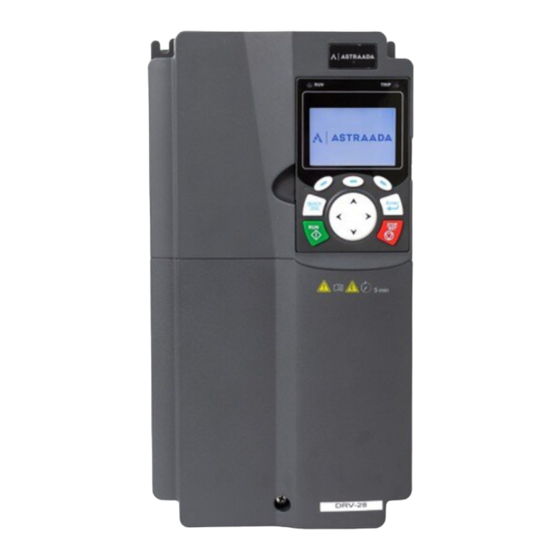
Astraada DRV-28A inverters ⚫ The rated output current is the output current corresponding to 380V output voltage. ⚫ Within the allowable input voltage range, the output current and power cannot exceed the rated output current and power. 3.10 Structure diagram... - Page 27 Astraada DRV-28A inverters Item Description Label of DRV-28 product See "Błąd! Nie można odnaleźć źródła odwołania.". series -21-...
-
Page 28: Installation Guidelines
Astraada DRV-28A inverters 4 Installation guidelines 4.1 What this chapter contains This chapter introduces the mechanical and electrical installations of the VFD. Only trained and qualified professionals are allowed to carry out the operations mentioned in this chapter. Please carry out operations according to instructions presented in Safety precautions. - Page 29 Astraada DRV-28A inverters Environment Condition Condensation is not allowed; The max RH cannot exceed 60% in the environment where there are corrosive gases. Storage -30–+60°C temperature The installation site should meet the following requirements. Away from electromagnetic radiation sources;...
- Page 30 Astraada DRV-28A inverters A. Vertical installation B. Horizontal installation C. Transverse installation Figure 4.1 Installation direction of the VFD 4.2.3 Installation mode There are three kinds of installation modes based on different VFD dimensions. Wall-mounting: suitable for AS28DRV4315A and lower models ⚫...
- Page 31 Astraada DRV-28A inverters 4.2.4 Single-unit installation Hot air Cold air Figure 4.3 Single-unit installation Note: The min. dimension of B and C is 100mm. 4.2.5 Multiple-unit installation Hot air Cold air Figure 4.4 Parallel installation Note: When you install VFDs in different sizes, align the top of each VFD before installation for the ⚫...
- Page 32 Astraada DRV-28A inverters 4.2.6 Vertical installation Windshield Cold Cold Windshield Figure 4.5 Vertical installation Note: During vertical installation, you must install windshield, otherwise, the VFD will experience -26-...
- Page 33 Astraada DRV-28A inverters mutual interference, and the heat dissipation effect will be degraded. 4.2.7 Tilted installation 热 风 冷 风 热 风 冷 风 热 风 冷 风 Figure 4.6 Tilted installation Note: During tilted installation, it is a must to ensure the air inlet duct and air outlet duct are separated from each other to avoid mutual interference.
-
Page 34: Main Circuit Standard Wiring
Astraada DRV-28A inverters 4.3 Main circuit standard wiring 4.3.1 Main circuit wiring diagram Brake resistor (+) (-) Output reactor Input 3-phase reactor 37kW and below Output power filter 380V±15% Input 50/60Hz filter Fuse Brake unit Brake resistor (+) (-) Output... - Page 35 Astraada DRV-28A inverters 4.3.2 Main circuit terminal diagram Figure 4.8 Main circuit terminal diagram for AS28DRV4022A and lower models Figure 4.9 Main circuit terminal diagram for AS28DRV4030A– AS28DRV4037A models Figure 4.10 Main circuit terminal diagram for AS28DRV4045A– AS28DRV4110A (optional built-in braking unit means starting PB) Figure 4.11 Main circuit terminal diagram for AS28DRV4132A–...
- Page 36 Astraada DRV-28A inverters Figure 4.12 Main circuit terminal diagram for AS28DRV4220A– AS28DRV4315Amodels Figure 4.13 Main circuit terminal diagram for AS28DRV4355A– AS28DRV4500A models -30-...
- Page 37 Astraada DRV-28A inverters Terminal Sign Function description AS28DRV4037A AS28DRV4045A– AS28DRV4132A and lower AS28DRV4110A and higher 3PH AC input terminal, R, S, T Main circuit power input connected to the grid. 3PH AC output terminal, U, V, W VFD output connected to the motor in most cases.
- Page 38 Astraada DRV-28A inverters 4.3.3 Wiring procedure of the main circuit terminals Connect the ground wire of the input power cable to the PE terminal of the VFD, connect the 3PH input cable to the R, S and T terminals, and tighten up.
-
Page 39: Control Circuit Standard Wiring
Astraada DRV-28A inverters 4.4 Control circuit standard wiring 4.4.1 Basic control circuit wiring diagram Forward running Analog output Forward jogging 0-10V/0-20mA Fault reset Y1 output HDIA HDIB High-speed pulse output and open collector output are available for choice. +24V 485+... - Page 40 Astraada DRV-28A inverters Terminal Description name ⚫ Whether the input is voltage or current is set through P05.50; ⚫ Resolution ratio: When 10V corresponds to 50Hz, the min. resolution ratio is 5mV; ⚫ Deviation: ±0.5% at 25°C, when input is above 5V/10mA.
- Page 41 Astraada DRV-28A inverters Terminal Description name speed-measurement function ⚫ Safe torque off (STO) redundant input, connected to the external +24V—H1 STO input 1 NC contact. When the contact opens, STO acts and the VFD stops output; ⚫ Safety input signal wires use shielded wires whose length is within 25m;...
-
Page 42: Wiring Protection
Astraada DRV-28A inverters + 24V +24V + 24V + 24V + 24V Internal power(NPN mode) External power(NPN mode) Figure 4.17 NPN mode If input signal comes from PNP transistor, set the U-type short connector based on the power used according to the following figure. - Page 43 Astraada DRV-28A inverters Input cable M3 ~ Fuse Figure 4.19 Fuse configuration Note: Select the fuse according to operation manual. During short-circuit, the fuse will protect input power cables to avoid damage to the VFD; when internal short-circuit occurred to the VFD, it can protect neighboring equipment from being damaged.
-
Page 44: Basic Operation Guidelines
Astraada DRV-28A inverters 5 Basic operation guidelines 5.1 What this chapter contains This chapter describes how to operate the VFD by using the keypad. 5.2 Keypad introduction The VFD has been equipped with the LCD keypad as a standard configuration part. You can use the keypad to control the start and stop, read status data, and set parameters of the VFD. - Page 45 Astraada DRV-28A inverters Item Description LED blinking: The VFD is autotuning parameters. LED on: The VFD is running. Fault indicator. LED on: in fault state TRIP LED off: in normal state LED blinking: in pre-alarm state Short-cut key indicator, which displays...
- Page 46 Astraada DRV-28A inverters Item Description setting, confirming parameter selection, and entering the next menu. When the VFD is controlled by the keypad, Run key this key is used to run the VFD or perform autotuning. In running state, pressing this key can stop running or autotuning;...
- Page 47 Astraada DRV-28A inverters Figure 5.2 Main interface of LCD Area Name Displayed contents Real-time display Display the real-time; clock battery is not included; the time Header A area needs to be reset when powering on the VFD. Display the running state of the VFD: Display motor rotating direction: "Forward"...
-
Page 48: Keypad Display
Astraada DRV-28A inverters Area Name Displayed contents Corresponding menus of function keys 4, 5 and 6. The Corresponding corresponding menus of function keys 4, 5 and 6 vary with Footer F menus of function interfaces, and the contents displayed in this area are also keys 4, 5 and 6 different. - Page 49 Astraada DRV-28A inverters 5.3.2 Displaying running-state parameters After receiving valid running command, the VFD will enter running state, and the keypad displays running state parameter with RUN indicator on the keypad turning on. Under running state, multiple kinds of state parameters can be displayed. Press to shift up or down.
-
Page 50: Operating The Vfd By Keypad
Astraada DRV-28A inverters Figure 5.7 Displaying a fault 5.4 Operating the VFD by keypad You can perform various operations on the VFD by using the keypad, including entering/exiting menus, parameter selection, list modification and parameter addition. 5.4.1 Enter/exit menu Regarding the monitoring menu, the operation relation between enter and exit is shown below. - Page 51 Astraada DRV-28A inverters Figure 5.9 Enter/exit menu diagram 2 The keypad menu setup is shown in the following. -45-...
- Page 52 Astraada DRV-28A inverters Level 1 Level 2 Level 3 Level 4 P00.10: Set frequency via keypad Common P00.00: Speed control mode parameter Pxx.xx : Common parameter setup setup xx Quick setup for function Pxx.xx code P00: Basic function group P00.xx P07: HMI group P07.xx...
- Page 53 Astraada DRV-28A inverters Level 1 Level 2 Level 3 Level 4 function P06: Output terminal group P06.xx group setup P98: AIAO calibration P98.xx function group P15: Communication expansion card 1 function P15.xx group P16: Communication expansion card 2 function P16.xx...
- Page 54 Astraada DRV-28A inverters Level 1 Level 2 Level 3 Level 4 fault P07.32: Type of the last but four fault P07.33: Running frequency of present fault P07.34: Ramps frequency of Fault state present fault P07.xx: xx state of the last but xx...
- Page 55 Astraada DRV-28A inverters Level 1 Level 2 Level 3 Level 4 Backlight brightness regulation Backlight time adjustment Power-on guiding enable Power-on guiding settings Keyboard burning selection Fault time enable Control board burning selection 5.4.2 List edit The monitoring items displayed in the parameter list of stop state can be added by users as needed (through the menu of the function code in state check group), and the list can also be edited by users e.g.
- Page 56 Astraada DRV-28A inverters including delete, shift-up and shift-down; the addition function can be set in a certain function code of a function group. The edit function is shown in the figure below. Figure 5.12 List edit diagram 3 5.4.3 Add parameters to the parameter list displayed in stop/running state In the fourth-level menu of "State monitoring", the parameters in the list can be added to the "parameter...
- Page 57 Astraada DRV-28A inverters 5.4.4 Add parameter to common parameter setup list In fourth-level menu of "parameter setup" menu, the parameter in the list can be added to the "common parameter setup" list as shown below. Figure 5.14 Add parameter diagram 2...
- Page 58 Astraada DRV-28A inverters "Default value" indicates the default value of this parameter. 5.4.6 Parameter setup edit interface In the fourth-level menu in "parameter setup" menu, press key, key or key to enter parameter setup edit interface. After entering edit interface, set the parameter from low bit to high bit, and the bit under setting will be highlighted.
- Page 59 Astraada DRV-28A inverters Figure 5.17 State monitoring interface 5.4.8 Motor parameter autotuning In "Motor parameter autotuning" menu, press key, key or key to enter motor parameter autotuning selection interface, however, before entering motor parameter autotuning interface, users must set the motor nameplate parameters correctly. After entering the interface, select motor autotuning type to carry out motor parameter autotuning.
- Page 60 Astraada DRV-28A inverters Figure 5.20 Parameter backup operation diagram 5.4.10 System setup In "System setup" menu, press key, key or key to enter system setup interface to set keypad language, time/date, backlight brightness, backlight time and restore parameters. Note: Clock battery is not included, and the keypad time/date needs to be reset after power off. If time- keeping after power off is needed, users should purchase the clock batteries separately.
- Page 61 Astraada DRV-28A inverters Level 1 Level 2 Level 3 Level 4 with the expectations? 2: AI2 0: AM P02.00 Type of motor 1 3: AI3 1: SM 4: High-speed P02.01 Rated pulse HDIA power of AM 1 P02.02 Rated 5: Simple PLC...
- Page 62 Astraada DRV-28A inverters Level 1 Level 2 Level 3 Level 4 Motor parameter 0: Keypad autotuning P00.01 interface Running command 1: Terminal channel Communication command 0: Modbus/ Modbus TCP communication 1: PROFIBUS / CANopen /Devicenet communication 2: Ethernet P00.02 Communication...
-
Page 63: Basic Operations
Astraada DRV-28A inverters Level 1 Level 2 Level 3 Level 4 2: VF control 3: Closed-loop vector control mode 0: Decelerate to P01.08 stop Stop mode 1: Coast to stop P00.11 ACC time 1 P00.12 DEC time 1 5.5 Basic operations 5.5.1 What this section contains... - Page 64 Astraada DRV-28A inverters Start Power up after confirming the wiring is correct Restore to default values Set the motor parameters of Set the motor parameters of P02.15–P02.19 as per the P02.01–P02.05 as per the motor nameplate motor nameplate Press QUICK/JOG to jog...
- Page 65 Astraada DRV-28A inverters Note: If fault occurred, rule out the fault cause according to "fault tracking". The running command channel can be set by terminal commands besides P00.01 and P00.02. Multi-function Multi-function terminal Multi-function terminal Current running terminal function (36)
- Page 66 Astraada DRV-28A inverters Function Name Description Default code where the motor cannot be disconnected from load. 3: Static autotuning 2 (partial autotuning); when the present motor is motor 1, only P02.06, P02.07 and P02.08 are autotuned; when the present motor is motor 2, only P12.06, P12.07 and P12.08 are autotuned.
- Page 67 Astraada DRV-28A inverters Function Name Description Default code Rated voltage of Model P02.18 0–1200V SM 1 depended Rated current of Model P02.19 0.8–6000.0A SM 1 depended 36: Switch the running command channel to Function selection keypad of multifunction P05.01– 37: Switch the running command channel to digital input P05.06...
- Page 68 Astraada DRV-28A inverters function parameters. R S T Rectifier bridge φ Calculate i exciting current Park IGBT conversion pulse bridge Calculate i torque current φ Position observation Voltage detection Speed identific ation Flux linkage observation Park Clark Current conversio conversion...
- Page 69 Astraada DRV-28A inverters Function Name Description Default code 4: Rotary autotuning 2. Similar to rotary autotuning 1, but it is valid only for AMs. 5: Static autotuning 3 (partial autotuning), valid only for AMs. Type of motor 0: Asynchronous motor (AM) P02.00...
- Page 70 Astraada DRV-28A inverters Function Name Description Default code integral coefficient I 11: Keypad (P03.12) 2: AI1 (100% corresponding to three times the motor rated current) 3: AI2 (same as the above) 4: AI3 (same as the above) 5: Pulse frequency HDIA (same as the above)
- Page 71 Astraada DRV-28A inverters Function Name Description Default code (same as the above) 8: Ethernet communication (same as the above) 9: Pulse frequency HDIB (same as the above) 10: EtherCat/Profinet/EtherNetIP communication 11: Programmable expansion card 12: Reserved Note: For setting methods 1–11, 100% corresponds to the maximum frequency.
- Page 72 Astraada DRV-28A inverters Function Name Description Default code 5: Modbus/Modbus TCP communication (same as the above) 6: Profibus/CANopen/DeviceNet communication (same as the above) 7: Ethernet communication (same as the above) 8: Pulse frequency HDIB (same as the above) 9: EtherCAT/Profinet communication...
- Page 73 Astraada DRV-28A inverters Function Name Description Default code constant power zone Max. voltage P03.24 0.0–120.0% 100.0% limit Pre-exciting P03.25 0.000–10.000s 0.300s time Enabling 0: Disable P03.32 torque control 1: Enable Flux 0–8000 1200 P03.33 weakening integral gain 0–0x1111 Ones place: Torque command selection...
- Page 74 Astraada DRV-28A inverters Function Name Description Default code coefficient and when the frequency is higher than the current- loop high-frequency switching threshold (P03.39), the High- current-loop PI parameters are P03.37 and P03.38. frequency Setting range of P03.37: 0–20000 current-loop P03.38 1000 Setting range of P03.38: 0–20000...
- Page 75 Astraada DRV-28A inverters Output voltage Torque -down V/F curve (power of 1.3) Torque -down V/F curve (power of 1.7) Straight-type Torque -down V/F curve (power of 2.0) Square-type Output frequency The VFD also provides multi-point V/F curves. You can change the V/F curves output by the VFD by setting the voltage and frequency of the three points in the middle.
- Page 76 Astraada DRV-28A inverters ⚫ Torque boost takes effect only at the torque boost cut-off frequency. ⚫ If torque boost is too large, the motor may encounter low-frequency vibration or overcurrent. If such a situation occurs, reduce the torque boost value.
- Page 77 Astraada DRV-28A inverters AM IF control Generally, the IF control mode is valid for AMs. It can be used for SMs only when the frequency is extremely low. Therefore, the IF control mode described in this manual is only involved with AMs. IF control is implemented by performing closed-loop control on the total output current of the VFD.
- Page 78 Astraada DRV-28A inverters When selecting the customized V/F curve function, you can specify the setting channels and acceleration/deceleration time of voltage and frequency respectively, which form a real-time V/F curve -72-...
- Page 79 Astraada DRV-28A inverters in combination manner. Note: This type of V/F curve separation can be applied in various variable-frequency power sources. However, exercise caution when setting parameters as improper settings may cause equipment damage. Function Name Description Default code 0: Sensorless vector control (SVC) mode 0...
- Page 80 Astraada DRV-28A inverters Function Name Description Default code V/F frequency P04.03 0.00Hz–P04.05 0.00Hz point 1 of motor 1 V/F voltage point 1 P04.04 0.0%–110.0% 0.0% of motor 1 V/F frequency P04.05 P04.03– P04.07 0.00Hz point 2 of motor 1 V/F voltage point 2 P04.06...
- Page 81 Astraada DRV-28A inverters Function Name Description Default code of motor 2 V/F frequency P04.18 P04.16– P04.20 0.00Hz point 2 of motor 2 V/F voltage point 2 P04.19 0.0%–110.0% 0.0% of motor 2 V/F frequency P04.20 P04.18– P02.02 or P04.18– P02.16 0.00Hz...
- Page 82 Astraada DRV-28A inverters Function Name Description Default code communication 12: Programmable expansion card 13: Reserved Voltage set P04.28 0.0%–100.0%(of the motor rated voltage) 100.0% through keypad Voltage increase P04.29 0.0–3600.0s 5.0s time Voltage decrease P04.30 0.0–3600.0s 5.0s time Max. output P04.31...
- Page 83 Astraada DRV-28A inverters Function Name Description Default code coefficient in SM control. V/F control Setting range: 0–3000 When the SM V/F control mode is enabled, the Reactive current function code is used to set the integral closed-loop P04.38 coefficient of reactive current closed-loop integral time in SM control.
- Page 84 Astraada DRV-28A inverters Function Name Description Default code for AM 2 1: Enable When IF control is adopted for AM 2, the function code is used to set the output current. Current setting in P04.46 The value is a percentage in relative to the 120.0%...
- Page 85 Astraada DRV-28A inverters -79-...
- Page 86 Astraada DRV-28A inverters Function Name Description Default code 0: Sensorless vector control (SVC) mode 0 1: Sensorless vector control (SVC) mode 1 2: Space voltage vector control mode Speed control P00.00 3: Closed-loop vector control mode mode Note: To select 0, 1, or 3 as the control mode, enable the VFD to perform motor parameter autotuning first.
- Page 87 Astraada DRV-28A inverters Function Name Description Default code 7: Profibus/CANopen/DeviceNet communication (same as the above) 8: Ethernet communication (same as the above) 9: Pulse frequency HDIB (same as the above) 10: EtherCat/Profinet/EtherNetIP communication 11: Programmable expansion card 12: Reserved Note: For setting methods 1–11, 100% corresponds to the maximum frequency.
- Page 88 Astraada DRV-28A inverters Function Name Description Default code torque upper limit motor rated current) 2: AI2 (same as the above) 3: AI3 (same as the above) 4: Pulse frequency HDIA (same as the above) 5: Modbus/Modbus TCP communication (same as...
- Page 89 Astraada DRV-28A inverters Function Name Description Default code through keypad P17.09 Output torque -250.0–250.0% 0.0% Torque reference P17.15 -300.0–300.0% (of the motor rated current) 0.0% value 5.5.6 Motor parameters Check the safety conditions surrounding the motor and load machineries before autotuning as physical injury may occur due to sudden start of motor during autotuning.
- Page 90 Astraada DRV-28A inverters Start Select running command channel (P00.01) Terminal Communication Keypad (P00.01=0) (P00.01=1) (P00.01=2) P08.31 set LED The switch-over ones to 0 channel for motor 1 and P08.31 sets motor 2 (P08.31) P08.31 sets P08.31 sets ones to 4...
- Page 91 Astraada DRV-28A inverters Ready P00.01=0 (controlled by keypad) Synchronous Asynchronous Motor type motor motor (P02.00) P02.00=1 P02.00=0 Input motor nameplate Input motor nameplate (P02.12–P02.19) (P02.01–P02.05) Set autotuning mode Complete parameter Complete parameter Partial parameter rotary rotary autotuning static autotuning autotuning Press "RUN"...
- Page 92 Astraada DRV-28A inverters ⚫ If rotary autotuning is selected during motor autotuning, disconnect the motor from the load to put the motor in static and no-load state. Otherwise, the motor parameter autotuning results may be incorrect. In addition, autotune P02.06–P02.10 for AMs and autotune P02.20–P02.23 for SMs.
- Page 93 Astraada DRV-28A inverters Function Name Description Default code 0: Asynchronous motor (AM) P02.00 Type of motor 1 1: Synchronous motor (SM) Model P02.01 Rated power of AM 1 0.1–3000.0kW depended Rated frequency of P02.02 0.01Hz–P00.03 (Max. output frequency) 50.00Hz AM 1 Model P02.03...
- Page 94 Astraada DRV-28A inverters Function Name Description Default code depended Stator resistance of Model P02.20 0.001–65.535Ω SM 1 depended Direct-axis inductance Model P02.21 0.01–655.35mH of SM 1 depended Quadrature-axis Model P02.22 0.01–655.35mH inductance of SM 1 depended P02.23 Counter-emf constant 0–10000...
- Page 95 Astraada DRV-28A inverters Function Name Description Default code AM 2 Model P12.03 Rated speed of AM 2 1–60000rpm depended Model P12.04 Rated voltage of AM 2 0–1200V depended Model P12.05 Rated current of AM 2 0.8–6000.0A depended Stator resistance of Model P12.06...
- Page 96 Astraada DRV-28A inverters Function Name Description Default code Quadrature-axis Model P12.22 0.01–655.35mH inductance of SM 2 depended P12.23 Counter-emf constant 0–10000 of SM 2 5.5.7 Start/stop control The start/stop control of the VFD involves three states: start after a running command is given at power-on;...
- Page 97 Astraada DRV-28A inverters -91-...
- Page 98 Astraada DRV-28A inverters Logic diagram for start after power-off restart is effective Standby Keypad The running state Stop Stop before power cut Restart after Communi power-cut cation Delay time of restart Waiting time of restart at >P01.123 power-cut>P01.22 P01.21 (restart at power-cut)
- Page 99 Astraada DRV-28A inverters Function Name Description Default code direct start Starting frequency hold P01.02 0.0–50.0s 0.0s time Braking current before P01.03 0.0–100.0% 0.0% start DC braking time before P01.04 0.00–50.00s 0.00s start 0: Linear 1: S curve P01.05 ACC and DEC mode Note: If mode 1 is selected, set P01.06,...
- Page 100 Astraada DRV-28A inverters Function Name Description Default code than frequency lower limit 2: Sleep (valid when frequency lower limit greater than 0) P01.20 Wake-up-from-sleep delay 0.0–3600.0s (valid when P01.19=2) 0.0s 0: Disable P01.21 Power-off restart selection 1: Enable Wait time for power-on P01.22...
- Page 101 Astraada DRV-28A inverters Function Name Description Default code 21: ACC/DEC time selection 1 22: ACC/DEC time selection 2 30: Disable ACC/DEC Model P08.00 ACC time 2 0.0–3600.0s depended Model P08.01 DEC time 2 0.0–3600.0s depended Model P08.02 ACC time 3 0.0–3600.0s...
- Page 102 Astraada DRV-28A inverters There is one input mode for auxiliary reference channel, namely terminal UP/DOWN switch input. By setting function codes, you can enable the corresponding reference mode and the impact made on the VFD frequency reference by this reference mode.
- Page 103 Astraada DRV-28A inverters Multifunction Multifunction Present Multifunction terminal function 14 terminal function 15 reference terminal function 13 Combination setting Combination setting channel Channel A switched switched to channel switched to channel P00.09 to channel B Max(A,B) Min(A,B) Note: "/" indicates this multifunction terminal is invalid under present reference channel.
- Page 104 Astraada DRV-28A inverters Function Name Description Default code frequency command 3: AI3 4: High-speed pulse HDIA 5: Simple PLC program 6: Multi-step speed running 7: PID control 8: Modbus/Modbus TCP communication 9: Profibus/CANopen/DeviceNet communication 10: Ethernet communication 11: High-speed pulse HDIB...
- Page 105 Astraada DRV-28A inverters Function Name Description Default code 0: The setting made through UP/DOWN is valid. 1: The setting made through UP/DOWN is invalid. Ones place: Frequency control selection 0: Valid only when P00.06=0 or P00.07=0 1: Valid for all frequency setting methods...
- Page 106 Astraada DRV-28A inverters Analog input curve setting Analog input filter P05.24 P05.25 P05.28 AI1 input voltage P05.26 P05.27 P17.19 P05.29 AI2 input voltage P05.30 P05.31 P17.20 P05.32 P05.37 P05.33 P05.34 P05.35 P05.36 HDIA input frequency P17.21 P05.39 HDIA P05.40 P05.43 P05.41...
- Page 107 Astraada DRV-28A inverters Function Name Description Default code Corresponding setting of P05.30 -300.0%–300.0% -100.0% AI2 lower limit P05.31 AI2 middle value 1 P05.29–P05.33 0.00V Corresponding setting of P05.32 -300.0%–300.0% 0.0% AI2 middle value 1 P05.33 AI2 middle value 2 P05.31–P05.35 0.00V...
- Page 108 Astraada DRV-28A inverters Function Name Description Default code 0: Voltage 1: Current 5.5.10 Analog output The VFD provides one analog output terminal (supporting 0–10V/0–20mA) and one high-speed pulse output terminal. Analog output signals can be filtered separately, and the proportional relation can be adjusted by setting the max.
- Page 109 Astraada DRV-28A inverters Setting Function Description AI2 input 0V–10V. A negative value corresponds to 0.0% by default. AI3 input 0–10V/0–20mA High-speed pulse HDIA input 0.00–50.00kHz Value 1 set through Modbus/Modbus TCP 0–1000 communication Value 2 set through Modbus/Modbus TCP 0–1000...
- Page 110 Astraada DRV-28A inverters Setting Function Description C_AO1 from PLC 0–1000 C_AO2 from PLC 0–1000 0–Twice the motor rated synchronous Rotational speed speed 0–Twice motor rated torque. A negative Output torque (bipolar) value corresponds to 0.0% by default. 31–47 Reserved Related parameter list:...
- Page 111 Astraada DRV-28A inverters Function Name Description Default code TCP (0–1000) 15: Value 2 set through Modbus/Modbus TCP (0–1000) Value through PROFIBUS/CANopen/DeviceNet (0– 1000) Value through PROFIBUS/CANopen/DeviceNet (0– 1000) 18: Value 1 set through Ethernet 1 (0– 1000) 19: Value 2 set through Ethernet 2 (0–...
- Page 112 Astraada DRV-28A inverters Function Name Description Default code P06.19 AO1 output upper limit P06.17–300.0% 100.0% AO1 output corresponding to P06.20 0.00V–10.00V 10.00V upper limit P06.21 AO1 output filter time 0.000s–10.000s 0.000s P06.22– Reserved 0–65535 P06.26 P06.27 HDO output lower limit -300.0%–P06.29...
- Page 113 Astraada DRV-28A inverters Setting Function Description Run forward (FWD) Control the forward/reverse running of the VFD by external terminals. Run reversely (REV) Set the VFD running mode to 3-wire control mode by this Three-wire running control terminal. See P05.13 for details.
- Page 114 Astraada DRV-28A inverters Setting Function Description and B setting A frequency reference channel and B frequency reference channel can be switched by no. 13 function; the Switch between combination channel set by P00.09 and the A frequency combination setting and A reference channel can be switched by no.
- Page 115 Astraada DRV-28A inverters Setting Function Description (back to the central frequency) Counter reset The counter is cleared. Switch between speed The VFD switches from torque control mode to speed control and torque control control mode, or vice versa. Used to ensure the VFD is not be impacted by external...
- Page 116 Astraada DRV-28A inverters Setting Function Description of braking torque upper is set through the keypad. limit to keypad Position reference point Valid only for S1, S2, and S3. input Disable spindle Used to disable spindle orientation. orientation Spindle zeroing / Local Used to trigger and enable spindle orientation.
- Page 117 Astraada DRV-28A inverters Setting Function Description When the thousands place of P21.00 determines to enable servo, the servo enabling terminal is valid, which controls to Enable servo VFD to enter zero servo control. At this time, a start command is not required.
- Page 118 Astraada DRV-28A inverters Function Name Description Default code 6: Coast to stop Function of HDIA P05.05 7: Fault reset terminal 8: Running pause Function of HDIB 9: External fault input P05.06 terminal 10: Frequency increase (UP) 11: Frequency decrease (DOWN)
- Page 119 Astraada DRV-28A inverters Function Name Description Default code 38: Command switches to communication 39: Pre-exciting command 40: Zero out power consumption quantity 41: Maintain power consumption quantity 42: Source of upper torque limit switches to keypad 56: Emergency stop 57: Motor over-temperature fault input...
- Page 120 Astraada DRV-28A inverters Function Name Description Default code S2 terminal switch-on P05.14 0.000–50.000s 0.000s delay S2 terminal switch-off P05.15 0.000–50.000s 0.000s delay S3 terminal switch-on P05.16 0.000–50.000s 0.000s delay S3 terminal switch-off P05.17 0.000–50.000s 0.000s delay S4 terminal switch-on P05.18 0.000–50.000s...
- Page 121 Astraada DRV-28A inverters P06.05 output polarity Digital output selection Digital switch-on delay Digital switch-off delay selection P17.12 Digital input P06.06 P06.07 terminal state T delay P06.01 T delay Fault? (Default value: 0) P07.40 Digital output Fault terminal state P06.08 P06.09...
- Page 122 Astraada DRV-28A inverters Setting Function Description P11.08–P11.10 for details. Output ON signal after the pre-alarm time Underload pre-alarm elapsed based on the pre-alarm threshold; see P11.11–P11.12 for details. Output signal when current stage of simple PLC is Simple PLC state completed...
- Page 123 Astraada DRV-28A inverters Setting Function Description Speed/position control switch-over Output is valid when the mode switch-over is completed completed 37–40 Reserved C_Y1 C_Y1 from PLC (You need to set P27.00 to 1.) C_Y2 C_Y2 from PLC (You need to set P27.00 to 1.) C_HDO C_HDO from PLC (You need to set P27.00 to 1.)
- Page 124 Astraada DRV-28A inverters Function Name Description Default code 20: External fault is valid 21: Reserved 22: Reach running time 23: Virtual terminal output of Modbus/Modbus TCP communication 24: Virtual terminal output of PROFIBUS/CANopen/DeviceNET communication 25: Virtual terminal output of Ethernet...
- Page 125 Astraada DRV-28A inverters Function Name Description Default code 47: C_RO4 from PLC (You need to set P27.00 to 1.) 48–63: Reserved Output terminal polarity P06.05 0x00–0x0F 0x00 selection P06.06 Y switch-on delay 0.000–50.000s 0.000s P06.07 Y switch-off delay 0.000–50.000s 0.000s P06.08...
- Page 126 Astraada DRV-28A inverters Digital output 16 Simple PLC state completed Digital output 17 Simple PLC cycle completed Related parameter list: Function Name Description Default code 23: Simple PLC stop reset P05.01– Digital input function 24: Pause simple PLC P05.06 selection 25: Pause PID control P06.01–...
- Page 127 Astraada DRV-28A inverters Function Name Description Default code P10.19 Running time of step 8 0.0–6553.5s (min) 0.0s P10.20 Multi-step speed 9 -100.0–100.0% 0.0% P10.21 Running time of step 9 0.0–6553.5s (min) 0.0s P10.22 Multi-step speed 10 -100.0–100.0% 0.0% P10.23 Running time of step 10 0.0–6553.5s (min)
- Page 128 Astraada DRV-28A inverters 5.5.14 Multi-step speed running The VFD can set 16-step speeds, which are selectable by multi-step speed terminals 1–4, corresponding to multi-step speed 0 to multi-step speed 15. P10.02 multi-step speed 0 BIT0 P10.34 P10.03 running time of 0...
- Page 129 Astraada DRV-28A inverters Function code Name Description Default P10.06 0.0% Multi-step speed 2 -100.0–100.0% P10.07 0.0s Running time of step 2 0.0–6553.5s (min) P10.08 0.0% Multi-step speed 3 -100.0–100.0% P10.09 0.0s Running time of step 3 0.0–6553.5s (min) P10.10 0.0% Multi-step speed 4 -100.0–100.0%...
- Page 130 Astraada DRV-28A inverters Function code Name Description Default Simple PLC and present Displays the present stage of P17.27 stage number of multi-step the simple PLC function. speed 5.5.15 PID control PID control, a common mode for process control, is mainly used to adjust the VFD output frequency...
- Page 131 Astraada DRV-28A inverters disappears. Integral regulator can be used to eliminate static difference; however, too large regulation may lead to repetitive overshoot, which will cause system instability and oscillation. The feature of oscillation caused by strong integral effect is that the feedback signal fluctuates up and down based on the reference variable, and fluctuation range increases gradually until oscillation occurred.
- Page 132 Astraada DRV-28A inverters Control overshoot: When overshoot occurred, shorten the derivative time (Td) and prolong integral time (Ti). Before adjustment Response After adjustment Time t Stabilize the feedback value as fast as possible: when overshoot occurred, shorten integral time (Ti) and prolong derivative time (Td) to stabilize control as fast as possible.
- Page 133 Astraada DRV-28A inverters After adjustment Response Before adjustment Time t Related parameter list: Function Name Description Default code 0: Keypad (P09.01) 1: AI1 2: AI2 3: AI3 4: High-speed pulse HDIA 5: Multi-step running PID reference 6: Modbus/Modbus TCP communication P09.00...
- Page 134 Astraada DRV-28A inverters Function Name Description Default code 8: EtherCat/Profinet/EtherNetIP communication 9: Programmable expansion card 10: Reserved PID output 0: PID output is positive characteristic P09.03 characteristics 1: PID output is negative characteristic selection Proportional gain 0.00–100.00 P09.04 1.80 (Kp) 0.01–10.00s...
- Page 135 Astraada DRV-28A inverters Function Name Description Default code 1: A+B frequency, acceleration/ deceleration of main reference A frequency source buffering is valid, acceleration/deceleration is determined by P08.04 (acceleration time 4). Low frequency P09.14 proportional gain 0.00–100.00 1.00 (Kp) ACC/DEC time of P09.15...
- Page 136 Astraada DRV-28A inverters Keypad P00.10 P00.06 (A frequency command Frequency set by Amplitude of wobbling selection) keypad frequency P08.05 Maintain current frequency Valid HDIA Valid Set frequency Wobbling Simple PLC Invalid Invalid frequency output Multi-step speed Terminal function 26 Terminal function 27...
- Page 137 Astraada DRV-28A inverters Function Name Description Default code center frequency) Amplitude of wobbling P08.15 0.0–100.0% (relative to set frequency) 0.0% frequency Amplitude of jump 0.0–50.0% (relative to amplitude of P08.16 0.0% frequency wobbling frequency) Wobbling frequency P08.17 0.1–3600.0s 5.0s rise time Wobbling frequency P08.18...
- Page 138 Astraada DRV-28A inverters 5.5.18 Commissioning procedures for closed-loop control, position control and spindle positioning 1. Commissioning procedures for closed-loop vector control of asynchronous motor Step 1: Restore to default value via keypad Step 2: Set P00.03, P00.04 and P02 group motor nameplate parameters...
- Page 139 Astraada DRV-28A inverters Step 1: Set P00.18=1, restore to default value Step 2: Set P00.00=3 (FVC), set P00.03, P00.04, and motor nameplate parameters in P02 group. Step 3: Set P20.01 encoder parameter. When the encoder is resolver-type encoder, set the encoder pulse count value to (resolver pole pair number ×...
- Page 140 Astraada DRV-28A inverters Step 2: Set P00.03, P00.04 and motor nameplate parameters in P02 group Step 3: Motor parameter autotuning: rotary parameter autotuning or static parameter autotuning Step 4: Verity the installation and settings of encoder. Set P00.00=3 and P00.10=20Hz to run the system, and check the control effect and performance of the system.
- Page 141 Astraada DRV-28A inverters Frequency Deceleration time of spindle orientation Speed of accurate-stop of spindle Time P21.09 Completion range of positioning Running command Zeroing command Zeroing selection terminal 1 Hold time of positioning completion signal Positioning completion signal P21.25 Hold time of positioning completion signal P21.10 Detection time...
- Page 142 Astraada DRV-28A inverters The priority level of speed running is higher than that of the scale division, when the system runs in scale-division mode, if spindle orientation is prohibited, the motor will turn to speed mode or position mode. The priority level of zeroing is higher than that of the scale division.
- Page 143 Astraada DRV-28A inverters Frequency Positioning speed P21.22 Hold time Time of positioning arrival Running command Cyclic positioning enable signal terminal Positioning completion signal P21.25 Hold time of positioning completion signal Step 1–4: These four steps are the same with the first four steps of the commissioning procedures for closed-loop vector control, which aim to fulfill the control requirements of closed-loop vector control.
- Page 144 Astraada DRV-28A inverters Step 5: Set P21.00=0021 to enable photoelectric switch positioning, the photoelectric switch signal can be connected to S8 terminal only, and set P05.08=43, meanwhile, set P21.17, P21.11 and P21.12 (set positioning displacement) based on actual needs; set P21.21 (deceleration time of positioning), however, when present running speed is too fast or the set positioning displacement is too small, the deceleration time of positioning will be invalid, and it will enter direct deceleration positioning mode.
- Page 145 Astraada DRV-28A inverters In running Fault occurred, and the keypad displayed fault code Figure out the fault cause based on the fault code Figure out the most possible cause according to P07.33– P07.40 Rule out fault based on corresponding solutions...
- Page 146 Astraada DRV-28A inverters Function Name Description Default code 12: VFD overload (OL2) 13: Phase loss on input side (SPI) 14: Phase loss on output side (SPO) 15: Rectifier module overheat (OH1) 16: Inverter module overheat (OH2) 17: External fault (EF)
- Page 147 Astraada DRV-28A inverters Function Name Description Default code 44: Safety code FLASH CRC fault (CrCE) 45: PLC card customized fault 1 (P-E1) 46: PLC card customized fault 2 (P-E2) 47: PLC card customized fault 3 (P-E3) 48: PLC card customized fault 4 (P-E4)
- Page 148 Astraada DRV-28A inverters Function Name Description Default code 72: EthernetIP communication timeout (E- EIP) Running frequency at P07.33 0.00Hz present fault Ramp reference P07.34 frequency at present 0.00Hz fault Output current at P07.35 present fault Output current at P07.36 0.0A...
- Page 149 Astraada DRV-28A inverters Function Name Description Default code frequency at 2nd-last fault Output voltage at 2nd- P07.51 last fault Output current at 2nd- P07.52 0.0A last fault Bus voltage at 2nd-last P07.53 0.0V fault Max temperature at 2nd- P07.54 -20.0–120.0°C 0.0°C...
-
Page 150: Function Parameter List
Astraada DRV-28A inverters 6 Function parameter list 5.5 What this chapter contains This chapter lists all the function codes and corresponding description of each function code. 5.6 Function parameter list The function parameters of the VFD are divided into groups by function. Among the function parameter groups, the P98 group is the analog input and output calibration group, while the P99 group contains the factory function parameters, which are user inaccessible. - Page 151 Astraada DRV-28A inverters parameter setting may cause operation exceptions or even damage to the VFD.) If password protection is not in locked state, you can change the password any time. You can set P07.00 to 0 to cancel the user password. When P07.00 is set to a non-zero value during power-on, parameters are prevented from being modified by using the user password function.
- Page 152 Astraada DRV-28A inverters Function Name Description Default Modify code When the set frequency is higher than the upper limit of the running frequency, the upper limit of the running frequency is used for running. Setting range: P00.05–P00.03 (Max. output frequency)
- Page 153 Astraada DRV-28A inverters Function Name Description Default Modify code of setting source 1: B 2: (A+B) 3: (A- B) 4: Max(A, B) 5: Min. (A, B) When A and B frequency commands select the keypad for setting, the value of the function...
- Page 154 Astraada DRV-28A inverters Function Name Description Default Modify code 1.5–11kW 8kHz 15–55kW 4kHz type Higher than 2kHz 75kW 2.2–15kW 4kHz Higher than type 2kHz 18.5kW Advantage of high carrier frequency: ideal current waveform, little current harmonic wave and motor noise.
- Page 155 Astraada DRV-28A inverters Function Name Description Default Modify code when the present motor is motor 1, only P02.06, P02.07 and P02.08 are autotuned; when the present motor is motor 2, only P12.06, P12.07 and P12.08 are autotuned. 4: Rotary autotuning 2. Similar to rotary autotuning 1, but it is valid only for AMs.
- Page 156 Astraada DRV-28A inverters Function Name Description Default Modify code Output frequency fmax F1 set by P01.01 T1 set by P01.02 Setting a proper starting frequency can increase the torque during VFD start. During Starting frequency P01.02 0.0s ◎ the hold time of the starting frequency, the...
- Page 157 Astraada DRV-28A inverters Function Name Description Default Modify code Output frequency f fmax Time t 1: S curve. The output frequency increases or decreases according to the S curve. The S curve is generally applied to elevators, conveyors, and other application scenarios where smoother start or stop is required.
- Page 158 Astraada DRV-28A inverters Function Name Description Default Modify code Starting frequency of DC braking for stop: Starting frequency During the deceleration to stop, the VFD P01.09 of DC braking for 0.00Hz ○ starts DC braking for stop when running stop...
- Page 159 Astraada DRV-28A inverters Function Name Description Default Modify code Setting range: 0.0–3600.0s 0: Switch at zero frequency FWD/REV running 1: Switch at the starting frequency P01.14 ◎ switching mode 2: Switch after the speed reaches the stop speed with a delay P01.15...
- Page 160 Astraada DRV-28A inverters Function Name Description Default Modify code again and it lasts for the time set by P01.20, the VFD resumes the running state automatically. The function code determines the wake-up- from-sleep delay time. When the running frequency of the VFD is lower than the lower limit, the VFD becomes standby.
- Page 161 Astraada DRV-28A inverters Function Name Description Default Modify code P01.21=1) After a VFD running command is given, the VFD is in standby state and restarts with the P01.23 Start delay delay defined by P01.23 to implement brake 0.0s ○ release.
- Page 162 Astraada DRV-28A inverters Function Name Description Default Modify code of braking for jogging to stop P01.34 Delay to enter sleep 0–3600.0s 0.0s ○ P02 group––Parameters of motor 1 0: Asynchronous motor (AM) P02.00 Type of motor 1 ◎ 1: Synchronous motor (SM)
- Page 163 Astraada DRV-28A inverters Function Name Description Default Modify code core of AM 1 Rated power of SM Model P02.15 0.1–3000.0kW ◎ depended Rated frequency of P02.16 0.01Hz–P00.03 (Max. output frequency) 50.00Hz ◎ SM 1 Number of pole P02.17 1–128 ◎...
- Page 164 Astraada DRV-28A inverters Function Name Description Default Modify code Motor overload multiples M=Iout/(In*K) In is rated motor current, lout is VFD output current, and K is motor overload protection coefficient. A smaller value of K indicates a bigger value of M.
- Page 165 Astraada DRV-28A inverters Function Name Description Default Modify code parameters P03.00–P03.05 Speed-loop P03.00 20.0 ○ applicable only to vector control mode. Below proportional gain 1 the switching frequency 1 (P03.02), the Speed-loop integral speed-loop PI parameters are: P03.00 and P03.01 0.200s...
- Page 166 Astraada DRV-28A inverters Function Name Description Default Modify code (Max. output frequency) Speed-loop output P03.06 0–8 (corresponding to 0–2^8/10ms) ○ filter Electromotive slip compensation Slip compensation coefficient is used to adjust P03.07 100% ○ coefficient of vector the slip frequency of the vector control and...
- Page 167 Astraada DRV-28A inverters Function Name Description Default Modify code EtherCat/Profinet/EthernetIP communication 12: Programmable expansion card Torque set through P03.12 -300.0%–300.0% (of the motor rated current) 20.0% ○ keypad Torque reference P03.13 0.000–10.000s 0.010s ○ filter time 0: Keypad (P03.16) 1: AI1 (100% corresponding to the max.
- Page 168 Astraada DRV-28A inverters Function Name Description Default Modify code 9: Pulse frequency HDIB (same as the above) EtherCat/Profinet/EthernetIP communication 11: Programmable expansion card 12: Reserved Forward rotation upper-limit The function codes are used to set the P03.16 frequency set 50.00Hz ○...
- Page 169 Astraada DRV-28A inverters Function Name Description Default Modify code Modbus/Modbus communication (same as the above) Profibus/CANopen/DeviceNet communication (same as the above) 7: Ethernet communication (same as the above) 8: Pulse frequency HDIB (same as the above) EtherCat/Profinet/EthernetIP communication 10: Programmable expansion card...
- Page 170 Astraada DRV-28A inverters Function Name Description Default Modify code VFD, which is the percentage of motor rated voltage. Set the value according to onsite conditions. Setting range: 0.0–120.0% Pre-exciting is performed for the motor when the VFD starts up. A magnetic field is built up P03.25...
- Page 171 Astraada DRV-28A inverters Function Name Description Default Modify code 0: Reserved 1: Reserved Hundreds place: indicates whether to enable speed-loop integral separation 0: Disable 1: Enable Thousands place: Reserved 0: Reserved 1: Reserved Range: 0x0000–0x1111 Speed-loop P03.36 0.00–10.00s 0.00s ○...
- Page 172 Astraada DRV-28A inverters Function Name Description Default Modify code identification to be performed properly. Setting range: 0.0–100.0% (of the motor rated torque) Enabling inertia 0: No operation P03.44 ◎ identification 1: Enable P03.45– Reserved 0–65535 ● P03.46 P04 group––V/F control...
- Page 173 Astraada DRV-28A inverters Function Name Description Default Modify code Torque boost of In order to compensate for low-frequency P04.01 0.0% ○ motor 1 torque characteristics, you can make some boost compensation for the output voltage. P04.01 is relative to the maximum output voltage V P04.02 defines the percentage of cut-off...
- Page 174 Astraada DRV-28A inverters Function Name Description Default Modify code The V/F curve is generally set according to the V/F voltage point 1 P04.04 00.0% ○ load characteristics of the motor. of motor 1 Note: V1 < V2 < V3, f1 < f2 < f3. Too high...
- Page 175 Astraada DRV-28A inverters Function Name Description Default Modify code corresponds to the rated slip frequency △f of motor 1. Setting range: 0.0–200.0% In space voltage vector control mode, the Low-frequency motor, especially the large-power motor, may P04.10 oscillation control ○...
- Page 176 Astraada DRV-28A inverters Function Name Description Default Modify code of motor 2 rated voltage of motor 2) Setting range of P04.20: P04.18– P12.02 V/F frequency point P04.20 0.00Hz ○ (rated frequency of AM 2) or P04.18– P12.16 3 of motor 2...
- Page 177 Astraada DRV-28A inverters Function Name Description Default Modify code 0: Keypad (The output voltage is determined by P04.28) 1: AI1 2: AI2 3: AI3 4: HDIA 5: Multi-step speed running (The setting is determined by group P10.) Voltage setting 6: PID P04.27...
- Page 178 Astraada DRV-28A inverters Function Name Description Default Modify code Setting range of P04.31: P04.32–100.0% (of the motor rated voltage) Setting range of P04.32: 0.0%–P04.31 Weakening coefficient in P04.33 1.00 ○ 1.00–1.30 constant power zone When the SM V/F control mode is enabled, the...
- Page 179 Astraada DRV-28A inverters Function Name Description Default Modify code When the SM V/F control mode is enabled, the function code is used to set the output limit of Reactive current the reactive current closed-loop control. A closed-loop output greater value indicates a higher reactive P04.39...
- Page 180 Astraada DRV-28A inverters Function Name Description Default Modify code coefficient in IF function code is used to set the proportional mode for AM 2 coefficient of output current closed-loop control. Setting range: 0–5000 When IF control is adopted for AM 2, the...
- Page 181 Astraada DRV-28A inverters Function Name Description Default Modify code Function of HDIA 8: Running pause P05.05 ◎ terminal 9: External fault input 10: Frequency increase (UP) 11: Frequency decrease (DOWN) 12: Clear frequency increase/decrease setting 13: Switch-over between setup A and setup B...
- Page 182 Astraada DRV-28A inverters Function Name Description Default Modify code 41: Maintain power consumption quantity 42: Source of upper torque limit switches to keypad 56: Emergency stop 57: Motor over-temperature fault input 59: Switch to V/F control 60: Switch to FVC control...
- Page 183 Astraada DRV-28A inverters Function Name Description Default Modify code 0: Two-wire control 1, the enabling consistent with the direction. This mode is widely used. The defined FWD/REV terminal command determines the motor rotation direction. Running command Stop Forward running Reverse...
- Page 184 Astraada DRV-28A inverters Function Name Description Default Modify code The direction control is as follows during running: Previous Present direction direction Run forward Run reversely → ON Run forward reversely ON→ Run forward reversely Run forward Run reversely ON→ Decelerate to stop Sin: Three-wire control;...
- Page 185 Astraada DRV-28A inverters Function Name Description Default Modify code forward forward reversely OFF→ON reversely ON→ Decelerate to stop Sin: Three-wire control; FWD: Forward running; REV: Reverse running Note: For two-wire controlled running mode, when the FWD/REV terminal is valid, if the...
- Page 186 Astraada DRV-28A inverters Function Name Description Default Modify code S4 switch-off delay address is 0x200A. P05.19 0.000s ○ HDIA switch-on P05.20 0.000s ○ delay HDIA switch-off P05.21 0.000s ○ delay HDIB switch-on P05.22 0.000s ○ delay HDIB switch-off P05.23 0.000s ○...
- Page 187 Astraada DRV-28A inverters Function Name Description Default Modify code setting of AI2 can enhance analog input anti-interference middle value 2 but may reduce the sensitivity of analog input. Note: AI1 supports the 0–10V/0–20mA input. P05.35 AI2 upper limit 10.00V ○...
- Page 188 Astraada DRV-28A inverters Function Name Description Default Modify code input filter time 0: Input set through frequency HDIB high-speed 1: Reserved P05.44 pulse input function ◎ 2: Input set through encoder, used together selection with HDIA HDIB lower limit 0.000 P05.45...
- Page 189 Astraada DRV-28A inverters Function Name Description Default Modify code 4: Jogging 5: VFD in fault 6: Frequency level detection FDT1 7: Frequency level detection FDT2 8: Frequency reached 9: Running in zero speed 10: Upper limit frequency reached 11: Lower limit frequency reached...
- Page 190 Astraada DRV-28A inverters Function Name Description Default Modify code 37: Any frequency reached 38–40: Reserved 41: C_Y1 from PLC (Set P27.00 to 1.) 42: C_Y2 from PLC (Set P27.00 to 1.) 43: C_HDO from PLC (Set P27.00 to 1.) 44: C_RO1 from PLC (Set P27.00 to 1.) 45: C_RO2 from PLC (Set P27.00 to 1.)
- Page 191 Astraada DRV-28A inverters Function Name Description Default Modify code frequency) P06.15 Reserved ○ 1: Set frequency (0–Max. output frequency) 2: Ramp reference frequency (0–Max. output frequency) 3: Rotational speed (0–Speed corresponding to max. output frequency) 4: Output current (0–Twice the VFD rated current) 5: Output current (0–Twice the motor rated...
- Page 192 Astraada DRV-28A inverters Function Name Description Default Modify code motor rated current) 24: Set frequency (bipolar, 0–Max. output frequency) 25: Ramp reference frequency (bipolar, 0– Max. output frequency) 26: Rotational speed (bipolar, 0–Speed corresponding to max. output frequency) Value through EtherCat/Profinet/EtherNetIP (0–1000)
- Page 193 Astraada DRV-28A inverters Function Name Description Default Modify code P06.22– Reserved 0–65535 ● P06.26 HDO output lower P06.27 -300.0%–P06.29 0.0% ○ limit HDO output P06.28 corresponding to 0.00–50.00kHz 0.00kHz ○ lower limit HDO output upper P06.29 P06.27–300.0% 100.0% ○ limit HDO output 50.00...
- Page 194 Astraada DRV-28A inverters Function Name Description Default Modify code need to enter the correct user password to enter the interface. Note: Restoring the default values may delete the user password. Exercise caution when using this function. P07.01 Reserved Range: 0x00–0x27...
- Page 195 Astraada DRV-28A inverters Function Name Description Default Modify code coefficient Display frequency = Running frequency * P07.08 0.1–999.9% Rotational speed Mechanical rotation speed = 120 * (Displayed P07.09 100.0% ○ display coefficient running frequency) *×P07.09/(Number of motor pole pairs) 0.1–999.9% Linear speed P07.10...
- Page 196 Astraada DRV-28A inverters Function Name Description Default Modify code P07.29 2nd-last fault type 2: Inverter unit V-phase protection (OUt2) ● 3: Inverter unit W-phase protection (OUt3) P07.30 3rd-last fault type ● 4: Overcurrent during acceleration (OC1) P07.31 4th-last fault type ●...
- Page 197 Astraada DRV-28A inverters Function Name Description Default Modify code 37: Encoder disconnection fault (ENC1O) 38: Encoder direction reversal fault (ENC1D) 39: Encoder Z-pulse disconnection fault (ENC1Z) 40: Safe torque off (STO) 41: Channel 1 safety circuit exception (STL1) 42: Channel 2 safety circuit exception (STL2)
- Page 198 Astraada DRV-28A inverters Function Name Description Default Modify code 70: Expansion card PT100 overtemperature (OtE1) 71: Expansion card PT1000 overtemperature (OtE2) 72: EthernetIP communication timeout (E- EIP) Running frequency P07.33 0.00Hz ● at present fault Ramp reference P07.34 frequency at 0.00Hz...
- Page 199 Astraada DRV-28A inverters Function Name Description Default Modify code last fault Input terminal P07.47 ● status at last fault Output terminal P07.48 ● status at last fault Running frequency P07.49 0.00Hz ● at 2nd-last fault Ramp reference P07.50 frequency at 2nd- 0.00Hz...
- Page 200 Astraada DRV-28A inverters Function Name Description Default Modify code The function code is used to define the Running frequency reference frequency during jogging. P08.06 5.00Hz ○ of jog Setting range: 0.00Hz–P00.03 (Max. output frequency) ACC time for jogging means the time needed Model P08.07...
- Page 201 Astraada DRV-28A inverters Function Name Description Default Modify code of ACC/DEC time 0.00Hz: No switchover If the running frequency is greater than P08.19, switch to ACC/DEC time 2. Frequency threshold of the P08.20 0.00–50.00Hz 2.00Hz ○ start of droop control 0: Max.
- Page 202 Astraada DRV-28A inverters Function Name Description Default Modify code decrease ratio in the load changes. The function code is mainly drop control used to balance the power when several motors drive a same load. Setting range: 0.00–50.00Hz 0x00–0x14 Ones place: Switchover channel...
- Page 203 Astraada DRV-28A inverters Function Name Description Default Modify code electrical level) Setting range of P08.34: 0.00Hz–P00.03 (Max. output frequency) Setting range of P08.35: 0.0–100.0% (FDT2 electrical level) When the output frequency is within the detection range, the multifunction digital output...
- Page 204 Astraada DRV-28A inverters Function Name Description Default Modify code modulation 1: PWM mode 2, 3PH modulation Tens place: PWM low-speed carrier limit 0: Low-speed carrier limit mode 1 1: Low-speed carrier limit mode 2 2: No limit Hundreds place: Deadzone compensation...
- Page 205 Astraada DRV-28A inverters Function Name Description Default Modify code 2: Invalid for multi-step speed running when multi-step speed running has the priority Hundreds place: Action selection for stop 0: Setting is valid. 1: Valid during running, cleared after stop 2: Valid during running, cleared after a stop...
- Page 206 Astraada DRV-28A inverters Function Name Description Default Modify code 0: Invalid 100–150: A greater coefficient indicates greater braking strength. The VFD can quickly slow down the motor by increasing the magnetic flux. The energy generated by the motor during braking can be transformed into heat energy by increasing the magnetic flux.
- Page 207 Astraada DRV-28A inverters Function Name Description Default Modify code in torque control 3: ACC/DEC time 3 4: ACC/DEC time 4 P09 group–– PID control When the frequency command selection (P00.06, P00.07) is 7 or the voltage setting channel selection ((P04.27) is 6, the VFD is process PID controlled.
- Page 208 Astraada DRV-28A inverters Function Name Description Default Modify code 3: HDIA 4: Modbus/Modbus TCP communication PROFIBUS/CANopen/DevicneNET communication 6: Ethernet communication 7: HDIB EtherCat/Profinet/EtherNetIP communication 9: Programmable expansion card 10: Reserved Note: The reference channel and feedback channel cannot be duplicate. Otherwise, effective PID control cannot be achieved.
- Page 209 Astraada DRV-28A inverters Function Name Description Default Modify code reference is 100%, the regulation of integral regulator (ignoring integral and differential actions), after undergoing continuous regulation during this time period, can reach max. output frequency (P00.03) or max. voltage (P04.31).
- Page 210 Astraada DRV-28A inverters Function Name Description Default Modify code Deviation Feedback limit Reference Time t Output frequency f Time t Setting range: 0.0–100.0% Upper limit value of The two function codes are used to set the P09.09 100.0% ○ PID output upper/lower limit value of PID regulator.
- Page 211 Astraada DRV-28A inverters Function Name Description Default Modify code reaches upper/lower limit Tens place: 0: The same with the main reference direction 1: Contrary to the main reference direction Hundreds place: 0: Limit based on the max. frequency 1: Limit based on A frequency...
- Page 212 Astraada DRV-28A inverters Function Name Description Default Modify code P09.28 P10 group––Simple PLC and multi-step speed control 0: Stop after running once; the VFD stops automatically after running for one cycle, and it can be started only after receiving running command.
- Page 213 Astraada DRV-28A inverters Function Name Description Default Modify code P10.16 Multi-step speed 7 When selecting multi-step speed running, the 0.0% ○ multi-step speed is within the range of -fmax– Running time of P10.17 ○ 0.0s(min) fmax, and it can be set continuously. The...
- Page 214 Astraada DRV-28A inverters Function Name Description Default Modify code OFF OFF OFF OFF ON ON ON ON ON ON ON ON ON ON ON ON Step ACC/DEC time of The description is as follows (St indicates P10.34 steps 0–7 of simple...
- Page 215 Astraada DRV-28A inverters Function Name Description Default Modify code P08.04 and P08.05. Setting range:0x0000–0xFFFF 0: Restart from the first step, namely if the VFD stops during running (caused by stop command, fault or power down), it will run from the first step after restart.
- Page 216 Astraada DRV-28A inverters Function Name Description Default Modify code 0: Disable 1: Enable DC bus voltage V Overvoltage stall threshold Overvoltage stall P11.03 ○ protection Time t Output frequency Time t 120–150% (standard bus voltage) (380V) 136% Overvoltage stall P11.04 ○...
- Page 217 Astraada DRV-28A inverters Function Name Description Default Modify code Output current A Current-limit threshold Time t Output frequency f frequency Constant Acceleration speed Time t Setting range of P11.06: 50.0–200.0% Setting range of P11.07: 0.00–50.00Hz/s 0x000–0x1132 Ones place: Motor overload/underload pre-alarm, relative to rated motor current;...
- Page 218 Astraada DRV-28A inverters Function Name Description Default Modify code overload pre-alarm signal will be outputted. Output current Overload pre-alarm threshold Overload pre-alarm Time t P11.10 1.0s ○ detection time Pre-alarm time t Pre-alarm time t RO1, RO2 Time t Setting range of P11.09: P11.11–200% Setting range of P11.10: 0.1–3600.0s...
- Page 219 Astraada DRV-28A inverters Function Name Description Default Modify code 0.0–10.0s Used to set the speed deviation detection time. Note: Speed deviation protection is invalid when P11.15 is set to 0.0. Speed Speed deviation Actual detection P11.15 2.0s ○ detection time...
- Page 220 Astraada DRV-28A inverters Function Name Description Default Modify code stall Proportional Used to set the proportional coefficient of the coefficient of bus voltage regulator during overvoltage stall. P11.21 voltage regulator ○ during overvoltage Setting range: 0–1000 stall Integral coefficient Used to set the integral coefficient of the bus of voltage regulator P11.22...
- Page 221 Astraada DRV-28A inverters Function Name Description Default Modify code 1: Method 2 Tens place: 0: Reserved 1: Reserved P12 group––Parameters of motor 2 0: Asynchronous motor (AM) P12.00 Type of motor 2 ◎ 1: Synchronous motor (SM) Rated power of AM Model P12.01...
- Page 222 Astraada DRV-28A inverters Function Name Description Default Modify code coefficient 4 of iron core of AM 2 Rated power of SM Model P12.15 0.1–3000.0kW ◎ depended Rated frequency of P12.16 0.01Hz–P00.03 (Max. output frequency) 50.00Hz ◎ SM 2 Number of pole P12.17...
- Page 223 Astraada DRV-28A inverters Function Name Description Default Modify code M≥400%, protection performed immediately. Time t Motor overload multiple 116 % 200 % Setting range: 20.0% –120.0% Power display calibration P12.28 0.00–3.00 1.00 ○ coefficient of motor 0: Display by motor type. In this mode, only...
- Page 224 Astraada DRV-28A inverters Function Name Description Default Modify code pull-in current switchover frequency threshold. If you need to increase the starting torque, increase the value of the function code properly. Setting range: 0.0%–100.0% (of the motor rated current) Pull-in current is the pole positioning current.
- Page 225 Astraada DRV-28A inverters Function Name Description Default Modify code The function code is used to adjust the responsiveness anti-maladjustment function. If the load inertia is large, increase Maladjustment P13.11 0.5s ○ the value of the function code properly, detection time however, the responsiveness may slow down accordingly.
- Page 226 Astraada DRV-28A inverters Function Name Description Default Modify code 5: 38400BPS 6: 57600BPS 7: 115200BPS Note: The baud rate set on the VFD must be consistent with that on the upper computer. Otherwise, the communication fails. A greater baud rate indicates faster communication.
- Page 227 Astraada DRV-28A inverters Function Name Description Default Modify code When continuous communication is required, you can set the function code to monitor communication status. 0: Report an alarm and coast to stop 1: Keep running without reporting an alarm 2: Stop in enabled stop mode without reporting Transmission error P14.05...
- Page 228 Astraada DRV-28A inverters Function Name Description Default Modify code 0: 50Kbps 1: 100 Kbps Master/slave CAN 2: 125Kbps P15.29 communication ◎ 3: 250Kbps baud rate selection 4: 500Kbps 5: 1M bps Master/slave CAN P15.30 communication 0.0 (invalid)–300.0s 0.0s ○ timeout time P15.31–...
- Page 229 Astraada DRV-28A inverters Function Name Description Default Modify code P17 group––Status viewing Displays current set frequency of the VFD. P17.00 Set frequency 50.00Hz ● Range: 0.00Hz–P00.03 Displays current output frequency of the VFD. P17.01 Output frequency 0.00Hz ● Range: 0.00Hz–P00.03...
- Page 230 Astraada DRV-28A inverters Function Name Description Default Modify code Range: 0.0–2000.0V Displays current digital input terminal state of the VFD. Digital input P17.12 0000–03F ● terminal state Corresponds to HDIB, HDIA, S4, S3, S2 and S1 respectively Displays current digital output terminal state of the VFD.
- Page 231 Astraada DRV-28A inverters Function Name Description Default Modify code Time elapsed of this Displays the time elapsed of this run. P17.26 ● Range: 0–65535min Simple PLC and Displays simple PLC and current step number P17.27 current step number of multi-step speed ●...
- Page 232 Astraada DRV-28A inverters Function Name Description Default Modify code Function code in P17.39 parameter 0.00–99.00 0.00 ● download error Ones place: Control mode 0: Vector control 0 1: Vector control 1 2: Space voltage vector control 3: Closed-loop vector control Tens place: Control status P17.40 Motor control mode...
- Page 233 Astraada DRV-28A inverters Function Name Description Default Modify code source Frequency set by B P17.50 0.00–P00.03 0.00Hz ● source PID proportional P17.51 -100.0%–100.0% 0.00% ● output P17.52 PID integral output -100.0%–100.0% 0.00% ● PID differential P17.53 -100.0%–100.0% 0.00% ● output PID present P17.54...
- Page 234 Astraada DRV-28A inverters Function Name Description Default Modify code value Range: 0–65535 Deviation between current reference position P18.07 Position deviation and actual running position. ● Range: -32768–32767 Position of reference point of Z pulse when the Position of position P18.08 spindle stops accurately.
- Page 235 Astraada DRV-28A inverters Function Name Description Default Modify code Range: -3276.8–3276.7Hz Pulse command (A2, B2 terminal) is converted to the set frequency, and it is valid Pulse command P18.18 0.00Hz ● under pulse position mode and pulse speed feedforward mode.
- Page 236 Astraada DRV-28A inverters Function Name Description Default Modify code pulse value Pulse-given main control board P18.32 -3276.8–3276.7Hz 0.0Hz ● measured speed value Pulse-given PG P18.33 card measured -3276.8–3276.7Hz 0.0Hz ● speed value Present encoder P18.34 0–63 ● filter width P18.35 Reserved 0–65535...
- Page 237 Astraada DRV-28A inverters Function Name Description Default Modify code expansion card at slot 1 Software version of P19.04 expansion card at 0.00–655.35 0.00 ● slot 2 Software version of P19.05 expansion card at 0.00–655.35 0.00 ● slot 3 Terminal input P19.06...
- Page 238 Astraada DRV-28A inverters Function Name Description Default Modify code 1: Reverse Detection time of Detection time of encoder offline fault. P20.03 2.0s ○ encoder offline fault Setting range: 0.0–10.0s Detection time of Detection time of encoder reversal fault. P20.04 encoder reversal 0.8s...
- Page 239 Astraada DRV-28A inverters Function Name Description Default Modify code pulse motor pole position. Setting range: 0.00–359.99 Relative electric angle of encoder position and Initial angle of the P20.10 motor pole position. 0.00 ○ pole Setting range: 0.00–359.99 0–3 1: Rotary autotuning (DC brake)
- Page 240 Astraada DRV-28A inverters Function Name Description Default Modify code division output filter 0: No filter 1: Filter Bit3: Reserved Bit4: Enable/disable pulse reference filter 0: No filter 1: Filter Bit5: Pulse reference filter mode (valid when Bit4 is set to 1) 0: Self-adaptive filter 1: Use P20.19 filter parameter...
- Page 241 Astraada DRV-28A inverters Function Name Description Default Modify code 0: Speed control 1: Position control Tens place: Position command source 0: Pulse string, using PG card terminal (A2, B2) pulse giving signal for position control 1: Digital position, using the setting of P21.17 for position control, while the positioning mode can be set through P21.16...
- Page 242 Astraada DRV-28A inverters Function Name Description Default Modify code 2: A: Positive pulse Channel A is positive pulse; channel B needs no wiring 3: A/B dual-channel pulse; channel A pulse edge counts up, channel B pulse edge counts down Tens place: Pulse direction...
- Page 243 Astraada DRV-28A inverters Function Name Description Default Modify code 0: No switching 2: Torque command 3: Speed command 3–5: Reserved Torque command Setting range: 0.0–100.0% (of the motor rated P21.05 level during position 10.0% ○ torque) gain switchover Speed command P21.06...
- Page 244 Astraada DRV-28A inverters Function Name Description Default Modify code Position 0.0–3200.0ms P21.14 feedforward filter For pulse string reference only (position 3.0ms ○ time constant control) The position feedforward filter time constant Position command P21.15 during pulse string positioning. 0.0ms ◎...
- Page 245 Astraada DRV-28A inverters Function Name Description Default Modify code 0: Pulse signal 1: Level signal Bit9: Position source 0: P21.17 setting 1: PROFIBUS/CANopen setting Bit10: Whether to save encoder pulse counting value at power failure 0: Not save 1: Save...
- Page 246 Astraada DRV-28A inverters Function Name Description Default Modify code Home position P21.24 0–65535 ○ offset The hold time of positioning completion signal, Hold time of the function code is also valid for positioning P21.25 positioning 0.200s ○ completion signal of spindle orientation.
- Page 247 Astraada DRV-28A inverters Function Name Description Default Modify code It is the filter time constant detected by pulse Speed feedforward string when the speed reference source is set filter time constant P21.29 pulse string (when 10.0ms ○ P00.06=12 (pulse string speed P00.07=12...
- Page 248 Astraada DRV-28A inverters Function Name Description Default Modify code 0: Calibrate at the first time 1: Calibrate in real time Bit8: Action selection after zeroing signal cancellation (electric level type) 0: Switch to speed mode 1: Position lock mode Bit9: Positioning completion signal selection...
- Page 249 Astraada DRV-28A inverters Function Name Description Default Modify code division angle 2 Spindle scale- P22.09 Setting range: 0.00–359.99 45.00 ○ division angle 3 Spindle scale- P22.10 Setting range: 0.00–359.99 60.00 ○ division angle 4 Spindle scale- P22.11 Setting range: 0.00–359.99 90.00...
- Page 250 Astraada DRV-28A inverters Function Name Description Default Modify code frequency of analog zero drift of rigid tapping P22.22 Reserved 0–1 ○ P22.23– Reserved 0–65535 ○ P22.24 P23 group––Vector control of motor 2 parameters P23.00–P23.05 Speed-loop P23.00 20.0 ○ applicable only to vector control mode. Below proportional gain 1 the switching frequency 1 (P23.02), the...
- Page 251 Astraada DRV-28A inverters Function Name Description Default Modify code demands. Setting range of P23.00: 0.0–200.0 Setting range of P23.01: 0.000–10.000s Setting range of P23.02: 0.00Hz–P23.05 Setting range of P23.03: 0.0–200.0 Setting range of P23.04: 0.000–10.000s Setting range of P23.05: P23.02–P00.03 (Max.
- Page 252 Astraada DRV-28A inverters Function Name Description Default Modify code coefficient high-frequency switching threshold, current-loop PI parameters are P23.12 and P23.13. Current-loop high- Setting range of P23.12: 0–65535 P23.14 frequency switching 100.0% ○ Setting range of P23.13: 0–65535 threshold Setting range of P23.14: 0.0–100.0% (of the max.
- Page 253 Astraada DRV-28A inverters Function Name Description Default Modify code between encoder encoder is not installed on the motor shaft mounting shaft and and the drive ratio is not 1. motor Setting range: 0.001–65.535 Bit0: Enable Z pulse calibration Bit1: Enable encoder angle calibration...
- Page 254 Astraada DRV-28A inverters Function Name Description Default Modify code measurement 1: Optimization mode 1 optimization 2: Optimization mode 2 selection CD signal zero P24.13 0–65535 ○ offset gain Ones place: Incremental encoder 0: without UVW Encoder type 1: with UVW P24.14...
- Page 255 Astraada DRV-28A inverters Function Name Description Default Modify code 0: Encoder signals 1: Pulse reference signals Bits7–15: Reserved 0–63 Encoder pulse filter P24.18 The filtering time is P24.18*0.25us. The value ○ width 0 or 1 indicates 0.25μs. 0–63 Pulse reference P24.19...
- Page 256 Astraada DRV-28A inverters Function Name Description Default Modify code Expansion card P25.08 input terminal 0x00–0x7F 0x00 ○ polarity selection 0x000–0x7F (0: Disable, 1: Enable) BIT0: S5 virtual terminal BIT1: S6 virtual terminal Virtual terminal BIT2: S7 virtual terminal P25.09 setting of expansion 0x00 ◎...
- Page 257 Astraada DRV-28A inverters Function Name Description Default Modify code P25.23 S10 switch-off delay 0.000s ○ P25.24 AI3 lower limit The function codes define the relationship 0.00V ○ between the analog input voltage and its Corresponding corresponding setting. When the analog input P25.25...
- Page 258 Astraada DRV-28A inverters Function Name Description Default Modify code Setting range of P25.29: 0.00V–P25.31 Setting range of P25.30: -300.0%–300.0% Setting range of P25.31: P25.29–10.00V Setting range of P25.32: -300.0%–300.0% Setting range of P25.33: 0.000s–10.000s HDI3 high-speed 0: Input set through frequency P25.34...
- Page 259 Astraada DRV-28A inverters Function Name Description Default Modify code P26.08 RO7 output ○ P26.09 RO8 output ○ P26.10 RO9 output ○ P26.11 RO10 output ○ Expansion card 0x0000–0x7FF P26.12 output terminal RO10, RO9…RO3, HDO2, 0x000 ○ polarity sequence HDO2 switch-on P26.13...
- Page 260 Astraada DRV-28A inverters Function Name Description Default Modify code RO8 switch-off P26.30 0.000s ○ delay RO9 switch-on P26.31 0.000s ○ delay RO9 switch-off P26.32 0.000s ○ delay RO10 switch-on P26.33 0.000s ○ delay RO10 switch-off P26.34 0.000s ○ delay P26.35 AO2 output ○...
- Page 261 Astraada DRV-28A inverters Function Name Description Default Modify code Setting range of P26.46: 0.00V–10.00V Setting range of P26.47: 0.000s–10.000s P26.48– 0–65535 Reserved ○ P26.52 P28 group––Master/slave control 0: Master/slave control is invalid P28.00 1: The local machine is a master ◎...
- Page 262 Astraada DRV-28A inverters Function Name Description Default Modify code Speed/torque mode 5.00Hz ○ switching frequency P28.05 point in 0.00–10.00Hz master/slave mode P28.06 Slave count 0–15 ◎ P28.07– Reserved 0–65535 ○ P28.24 0: Invalid 1: Fire mode 1 2: Fire mode 2 When P90.00=0, the fire mode is invalid, and...
- Page 263 Astraada DRV-28A inverters Function Name Description Default Modify code P91 group––Customized function group 2 P91.00– Reserved 0–65535 ○ P91.39 P92 group––Customized function group 3 P92.00– Reserved 0–65535 ○ P92.39 P93 group––Customized function group 4 P93.00– Reserved 0–65535 ○ P93.39 -257-...
-
Page 264: Troubleshooting
Astraada DRV-28A inverters 7 Troubleshooting 7.1 What this chapter contains The chapter instructs you how to reset faults and check faults history. A complete list of alarms and fault information as well as possible causes and corrective measures are presented in this chapter. - Page 265 Astraada DRV-28A inverters Fault Fault type Possible cause Solution code protection peripheral equipment Inverter unit OUt3 Phase-W protection Over-voltage Check input power; during Check whether load acceleration Exception occurred to input deceleration time is too short; Over-voltage voltage; or the motor starts during during Large energy feedback;...
- Page 266 Astraada DRV-28A inverters Fault Fault type Possible cause Solution code Load is too large; Select the VFD with larger Power is too small; power; Select proper motor Phase loss on Phase loss or violent fluctuation Check the input power; input side...
- Page 267 Astraada DRV-28A inverters Fault Fault type Possible cause Solution code the rated frequency R/W error occurred to the control Press STOP/RST to reset; EEPROM fault parameters; Replace the main control board EEPROM is damaged Check PID feedback signal PID feedback PID feedback offline;...
- Page 268 Astraada DRV-28A inverters Fault Fault type Possible cause Solution code circuit fault 1 to the ground; proper; Current detection circuit is faulty; Replace the hall component; Actual motor power setup Replace the main control board; deviates sharply from the VFD...
- Page 269 Astraada DRV-28A inverters Fault Fault type Possible cause Solution code occurred to resistor; sensor is proper; Long-time overload running or Check the motor and perform exception occurred maintenance on the motor Safe torque off function is enabled Safe torque off...
- Page 270 Astraada DRV-28A inverters Fault Fault type Possible cause Solution code Check whether the insertion port is damaged, if yes, replace the insertion port after power down Confirm whether the expansion card inserted can be supported; Stabilize the expansion card interfaces after power down,...
- Page 271 Astraada DRV-28A inverters Fault Fault type Possible cause Solution code and confirm whether fault still in card slot 2 occurs at next power-on; Check whether the insertion port is damaged, if yes, replace the insertion port after power down Confirm whether the expansion card inserted can be supported;...
- Page 272 Astraada DRV-28A inverters Fault Fault type Possible cause Solution code Check whether the communication card wiring is master/slave There is no data transmission loose or dropped communication ESCAN between the CAN master and card slave communication cards communication timeout fault...
-
Page 273: Analysis On Common Faults
Astraada DRV-28A inverters 7.6 Analysis on common faults 7.6.1 Motor fails to work Motor fails to work Whether the POWER Whether the air switch indicator is on? Close the air and EM contactor on the Whether the keypad contactor input side are closed? - Page 274 Astraada DRV-28A inverters 7.6.2 Motor vibrates Motor vibrates or emits an unusual sound Whether the motor Set the motor type parameters and motor type and parameters are set correctly ? correctly Whether autotuning is Perform autotuning performed? Whether the V/F...
- Page 275 Astraada DRV-28A inverters 7.6.3 Overvoltage Overvoltage fault Whether the voltage of the Ensure the power supply power supply is within the meets the requirement standard range? Whether UVW on the output side of the VFD is short to Rectify the short-circuit...
- Page 276 Astraada DRV-28A inverters 7.6.5 Unusual heating of motor Unusual heating of the motor Set the motor Whether the motor parameters parameters are set correctly? correctly Whether parameter Parameter autotuning is autotune performed? Whether the VFD runs at a low speed all the time?
- Page 277 Astraada DRV-28A inverters 7.6.6 VFD overheating VFD overheating Whether the load is too Reduce the load and heavy or the capacity of increase the capacity the VFD is too small? of the inverter Whether the ambient Add a cooling device...
- Page 278 Astraada DRV-28A inverters 7.6.7 Motor stalls during ACC Motor stalls during Whether the ACC Increase the ACC time is too short? time Check the voltage of the Use larger cables, shorten the terminals of the motor with a wiring distance, adjust the voltage multimeter.
-
Page 279: Countermeasures On Common Interference
Astraada DRV-28A inverters 7.6.8 Overcurrent Overcurrent Whether UVW on the Rectify the short-to- output side of the VFD is ground fault, and short to ground? Remove configure the motor the motor cable and cables properly checked whether it is connected to earth. - Page 280 Astraada DRV-28A inverters started: 1. The upper or lower limit is wrongly displayed, for example, 999 or -999. 2. The display of values jumps (usually occurring on pressure transmitters). 3. The display of values is stable, but there is a large deviation, for example, the temperature is dozens of degrees higher than the common temperature (usually occurring on thermocouples).
- Page 281 Astraada DRV-28A inverters external C2 filter on the input power end of the VFD. For models of filters, see the filter model selection section D.7.2 Filter model selection. 7.7.2 Interference on RS485 communication Interference phenomenon The interference described in this section on 485 communication mainly includes communication delay, synchronization failure, occasional power-off, or complete power-off that occurs after the VFD is started.
- Page 282 Astraada DRV-28A inverters Try to add a safety capacitor of 0.1 μF on the power terminal of the upper computer (PLC, HMI, and touch screen). During this process, pay attention to the voltage of the power supply and the voltage endurance capability of the capacitor.
- Page 283 Astraada DRV-28A inverters difference between two actions need to be longer than 20 ms. For example, 1s, 0.5s, and 0.2s. For circuits in VFD systems, electromagnetic RCDs are recommended. Electromagnetic RCDs have strong anti-interference capability, and thus can prevent the impact of high-frequency leakage current.
-
Page 284: Maintenance
Astraada DRV-28A inverters 8 Maintenance 8.1 What this chapter contains This chapter describes how to carry out preventive maintenance on the VFD. 8.2 Periodical inspection Only little maintenance is required when the VFD is installed in an environment that meets the requirements. - Page 285 Astraada DRV-28A inverters Subject Item Method Criterion cannot work properly. Check whether the conductors are deformed or No exception Visual inspection their color change due to occurs. Conductor and overheat. wire Check whether the wire No exception sheaths are cracked or their Visual inspection occurs.
-
Page 286: Cooling Fan
Astraada DRV-28A inverters Subject Item Method Criterion contactor and vibration sounds in the occurs. relay workshop. Check whether the contacts No exception Visual inspection are in good contact. occurs. Check whether the screws No exception Screw them up. and connectors loose. -
Page 287: Capacitor
Astraada DRV-28A inverters You can view the running duration of the VFD through P07.14 (Accumulated running time). The increase of the bearing noise indicates a fan fault. If the VFD is applied in a key position, replace the fan once the fan starts to generate unusual noise. You can purchase spare parts of fans from ASTOR. - Page 288 Astraada DRV-28A inverters Storage time Operation instruction Less than 1 year No charging operation is required. The VFD needs to be powered on for 1 hour before the first running 1 to 2 years command. Use a voltage controlled power supply to charge the VFD:...
-
Page 289: Power Cable
Astraada DRV-28A inverters Resistor 1 KΩ/100 W Power supply Resistor 1 KΩ/100 W 380 V Resistor 1 KΩ/100 W Figure 8.2 Charging circuit example of driving devices 8.4.2 Electrolytic capacitor replacement Read the safety precautions carefully and follow the instructions to perform operations. -
Page 290: Communication
Astraada DRV-28A inverters 9 Communication 9.1 What this chapter contains This chapter describes the communication protocols supported by the VFD. The VFD provides RS485 communication interfaces and adopts the master/slave communication based on the international standard Modbus communication protocol. You can implement centralized... - Page 291 Astraada DRV-28A inverters Max. transmission Max. transmission Baud rate (bps) Baud rate (bps) distance (meter) distance (meter) 2400BPS 1800m 9600BPS 800m 4800BPS 1200m 19200BPS 600m When RS485 interfaces are used for long-distance communication, it is recommended that you use shielded cables, and use the shielding layer as the ground wires.
- Page 292 Astraada DRV-28A inverters 120Ω 120Ω 32 # Figure 9.2 Onsite chrysanthemum connection diagram Master Figure 9.3 Simplified chrysanthemum connection diagram Shielded twisted pair 120Ω 485 + 485+ 485 + Terminal resistor 485- 485 - 485- Ground Ground Ground RS232- 485...
- Page 293 Astraada DRV-28A inverters Figure 9.5 Star connection Use shielded cables, if possible, in multi-VFD connection. The baud rates, data bit check settings, and other basic parameters of all the devices on the RS485 line must be set consistently, and addresses cannot be repeated.
- Page 294 Astraada DRV-28A inverters to facilitate the transmission of the data bits to the destination device. In practical applications, you must set the data bits, parity check bits, and stop bits consistently. In RTU mode, a new frame always must be preceded by a time gap with a minimum length of 3.5 bytes.
- Page 295 Astraada DRV-28A inverters may cause severe problems. Therefore, the data must be checked. The check is implemented as follows: The transmitter calculates the to-be-transmitted data based on a specific algorithm to obtain a result, adds the result to the rear of the message, and transmits them together.
-
Page 296: Rtu Command Code And Communication Data
Astraada DRV-28A inverters bit) is detected and processed, the XOR operation is performed on the next 8-bit byte and the current content in the register. The final values in the register are the CRC values obtained after operations are performed on all the bytes in the frame. - Page 297 Astraada DRV-28A inverters frame structures are described in the following. RTU master command (sent from the master to the VFD): START T1-T2-T3-T4 (time gap with a min. length of 3.5 bytes) ADDR (address) CMD (command code) Start address high-order bit...
- Page 298 Astraada DRV-28A inverters High-order bit of data in 0004H T1-T2-T3-T4 (time gap with a min. length of 3.5 bytes) The definition of the response information is described as follows: "ADDR" is "01H", indicating that the message is sent from the VFD whose address is 01H. The ADDR information occupies one byte.
- Page 299 Astraada DRV-28A inverters 3.5 bytes) ADDR High-order bit of data writing address Low-order bit of data writing address Data content high-order bit Data content low-order bit CRC low-order bit CRC high-order bit T1-T2-T3-T4 (time gap with a min. length of 3.5 bytes)
- Page 300 Astraada DRV-28A inverters T1-T2-T3-T4 (time gap with a min. length of START 3.5 bytes) ADDR Sub-function code high-order bit Sub-function code low-order bit Data content high-order bit Data content low-order bit CRC CHK low-order bit CRC CHK high-order bit T1-T2-T3-T4 (time gap with a min. length of 3.5 bytes)
- Page 301 Astraada DRV-28A inverters 3.5 bytes) ADDR High-order bit of data writing address Low-order bit of data writing address Data count high-order bit Data count low-order bit CRC low-order bit CRC high-order bit T1-T2-T3-T4 (time gap with a min. length of 3.5 bytes)
- Page 302 Astraada DRV-28A inverters regardless of the VFD status. Pay attention to the setting range, unit, and description of a parameter when modifying it. ⚫ The service life of the Electrically Erasable Programmable Read-Only Memory (EEPROM) may be reduced if it is frequently used for storage. Some function codes do not need to be stored during communication.
- Page 303 Astraada DRV-28A inverters Function Address Data description Setting of the upper limit of the reverse running 2006H frequency (0–Fmax, unit: 0.01 Hz) Upper limit of the electromotion torque (0–3000, 2007H 1000 corresponding to 100.0% of the motor rated current) Upper limit of the brake torque (0–3000, 1000 2008H corresponding to 100.0% of the motor rated...
- Page 304 Astraada DRV-28A inverters Function Address Data description 0004H: Faulty 0005H: POFF 0006H: Pre-excited Bit0: =0: Not ready to run =1: Ready to run Bi1–2: =00: Motor 1 =01: Motor 2 Bit3: =0: Asynchronous motor =1: Synchronous motor Bit4: =0: No overload alarm =1: Overload alarm Bit5–Bit6: =00: Keypad-based control...
- Page 305 Astraada DRV-28A inverters Function Address Data description Closed-loop setting 3008H -100.0–100.0% (Unit: 0.1%) Closed-loop feedback 3009H -100.0–100.0% (Unit: 0.1%) 000–3F Input state 300AH Corresponding to the local HDIB/ HDIA/S4/S3/S2/S1 000–0F Output state 300BH Corresponding local RO2/RO1/HDO/Y1 300CH 0.00–10.00V (Unit: 0.01V)
- Page 306 Astraada DRV-28A inverters reference source" (P09.00) to Modbus communication. The following table describes the encoding rules of device codes (corresponding to the identification code 2103H of the VFD). Eight high- Eight low- order bits of Meaning order bits of Meaning...
- Page 307 Astraada DRV-28A inverters 01 14 00 32 49 E7 Parameter Parameter Write address command address data After receiving the command, the VFD converts 50 into 5.0 based on the fieldbus scale, and then sets "Wake-up-from-sleep delay" to 5.0s. For another example, after the upper computer transmits the "Wake-up-from-sleep delay" parameter...
- Page 308 Astraada DRV-28A inverters Code Name Description failure example, a function input terminal cannot be set repeatedly. Password The password entered in the password verification address is different error from that set in P07.00. The length of the data frame transmitted by the upper computer is...
- Page 309 Astraada DRV-28A inverters 00 01 00 03 98 0B Parameter Parameter Read data address command address However, the setting range of the "Running command channel" is 0 to 2. The value 3 exceeds the setting range. In this case, the VFD returns an error message response as shown in the following:...
- Page 310 Astraada DRV-28A inverters Assume that the following response is returned: 03 03 0C 00 23 00 23 00 23 00 23 00 23 00 23 5F D2 5th-last fault 4th-last fault Last fault 2nd-last fault 3rd-last fault Read Number of...
- Page 311 Astraada DRV-28A inverters Function Setting Name Description Default Modify code range Max. output P00.04–600.00H 100.00– P00.03 50.00Hz ◎ frequency (400.00Hz) 600.00 According to the number of decimals, the fieldbus scale of the "Max. output frequency" (P00.03) is 100. Multiply 100 Hz by 100. The value 10000 is obtained, and it is 2710H in the hexadecimal form.
- Page 312 Astraada DRV-28A inverters Function Address Data description 0007H: Fault reset 0008H: Jogging to stop Communication-based frequency setting (0– 2001H Fmax, unit: 0.01 Hz) Communication-based value setting PID setting, range (0–1000, 1000 2002H corresponding to 100.0%) In the actual operation, set P00.01 to 2 and P00.06 to 8.
- Page 313 Astraada DRV-28A inverters 00 0B 00 02 30 0A Parameter Continuous Parameter address address quantity write command Note: In the preceding command description, spaces are added to a command just for explanatory purposes. In practical applications, no space is required in the commands.
-
Page 314: Common Communication Faults
Astraada DRV-28A inverters Set the address (P14.00) of the VFD to 03. Set "Channel of running commands" (P00.01) to "Communication", and set "Communication channel of running commands" (P00.02) to the Modbus communication channel. Click Send. If the line configuration and settings are correct, a response transmitted by the VFD is... -
Page 315: Appendix A Expansion Cards
Astraada DRV-28A inverters Appendix A Expansion cards A.1 Model definition AS 28 XXX ① ② ③ ④ ⑤ -309-... - Page 316 Astraada DRV-28A inverters Detailed Detailed content description ① Brand Brand abbreviation AS: Astraada 28: DRV-28 optional cards 20: Inverter peripherial devices (filters, ② Type Inverter series reactors, braking systems, extension cards) BTH: Bluetooth extension cards PBS: Profibus extension cards PNS: Profinet extension cards ETH: Ethernet extension cards ③...
- Page 317 Astraada DRV-28A inverters For communications (PBS. PNS, ETH) extension cards: 001: 1 version of extension card For CAN: 001: CANopen extension card 002: CAN Master-slave extension card For Bluetooth: 001: extension card with internal antenna 002: extension card with external antenna...
- Page 318 2 digital outputs 2 relay outputs: 1 double-contact output, and 1 single-contact output Supporting Bluetooth 4.0 With Astraada's mobile phone APP, you can set the parameters and monitor the states of the inverter through Bluetooth Bluetooth AS28BTH0001 ...
- Page 319 Supporting Ethernet communication with internal protocol Ethernet AS28ETH0001 communication card Can be used in combination with upper computer monitoring software Astraada DRV CFG Based on the CAN2.0A physical layer CANopen AS28CAN0001 communication card Supporting the CANopen protocol ...
- Page 320 Astraada DRV-28A inverters Name Model Specification Applicable to 5 V differential encoders Supporting A, B, Z orthogonal input Supporting A, B, Z frequency-divided output Supporting pulse string reference input Applicable to differential encoders of 5 V ...
- Page 321 Astraada DRV-28A inverters Ethernet CANopen/CAN PROFINET Sin/Cos PG card communication card master/slave control communication card AS28ENC0006 AS28ETH0001 communication card AS28PNS0001 AS28CAN000x UVW incremental Resolver PG card Multi-function 24V incremental PG PG card incremental PG card AS28ENC0002 card AS28ENC0004 AS28ENC0001 AS28ENC0003...
-
Page 322: Dimensions And Installation
Astraada DRV-28A inverters Simplified incremental PG card AS28ENC0005 A.2 Dimensions and installation All expansion cards are of the same dimensions (108 mm × 39 mm) and can be installed in the same way. Following the operation principles when installing or removing an expansion card: ⚫... - Page 323 Astraada DRV-28A inverters EC 1 EC 1 EC 2 EC 2 EC 3 EC 3 EC installation diagram Diagram of ECs installed Figure A.1 AS28DRV47C5A or higher models with expansion cards installed EC 1 EC 1 EC 2 EC 2...
- Page 324 Astraada DRV-28A inverters Expansion card installation process: STEP 1 Unscrew the screws and remove th e lower cover STEP 2 STEP 3 Unscrew the screws, take out the keypad, and remove the upper cover Insert the EC STEP 4 Align the EC positioning holes...
-
Page 325: Wiring
Astraada DRV-28A inverters A.3 Wiring 1. Ground a shielded cable as follows: Grounding position of the shielded cable Grounding position of the shielded cable Figure A.4 Expansion card grounding diagram 2. Wire an expansion card as follows: EC wiring EC wire binding position Figure A.5 Expansion card wiring... - Page 326 Astraada DRV-28A inverters The terminals are arranged as follows: CME and COM are shorted through J3 before delivery, and J5 is the jumper for selecting the output type (voltage or current) of AO2. RO3A RO3B RO3C +24V RO4A RO4C Indicator definition:...
-
Page 327: Programmable Expansion Card-- As28Enc0003
Astraada DRV-28A inverters Category Sign Name Function 5. Deviation:±0.5%; input of 5 V or 10 mA or higher at the temperature of 25°C 1. Output range: 0–10 V, 0–20 mA 2. Whether it is voltage or current output is AO2—GND Analog output 1 determined by J5. - Page 328 Astraada DRV-28A inverters type input selection and voltage type input selection of AI1, and they can be selected through J2. "AIO" and "AVO" are the current type output selection and voltage type output selection of AO1, and they can be selected through J5. "120" indicates 120Ω...
- Page 329 Astraada DRV-28A inverters input, 1 analog output, and 1 RS485 communication channel (for master/slave switchover). It is user- friendly, providing relay outputs through European-type screw terminals and other inputs and outputs through spring terminals. AS28PLC0001 terminal function description: Category Sign...
-
Page 330: Communication Card Function Description
Common PRO2C contact of relay For details about the operation of programmable expansion cards, see the Astraada DRV-28A Series VFD Auto Station Programmable Expansion Card Operation Manual. A.6 Communication card function description A.6.1 Bluetooth communication card–– AS28BTH000x and WIFI card –– AS28WIF000x... - Page 331 Astraada DRV-28A inverters Indicator/button Name Function card is disconnected from the control board. This indicator when Bluetooth communication is online and data exchange Bluetooth can be performed. LED2 communication state indicator It is off when Bluetooth communication is not in the online state.
- Page 332 Astraada DRV-28A inverters The wireless communication card must be used with the ASTOR VFD APP. Scan the QR code of the VFD nameplate to download it. For details, refer to the wireless communication card manual provided with the expansion card. The main interface is shown as follows.
- Page 333 Astraada DRV-28A inverters A.6.2 PROFIBUS-DP communication card–– AS28PBS0001 CN1 is a 9-pin D-type connector, as shown in the following figure. Connector pin Description Unused Unused B-Line Data+ (twisted pair 1) Request sending GND_BUS Isolation ground +5V BUS Isolated power supply of 5 V DC...
- Page 334 It is off when the diagnosis function is disabled. This indicator is on after the control board feeds LED4 Power indicator power to the communication card. For details about the operation, see the Astraada DRV-28A Series VFD Communication Expansion Card Operation Manual. -328-...
- Page 335 Astraada DRV-28A inverters A.6.3 Ethernet communication card–– AS28ETH0001 The AS28ETH0001 communication card adopts standard RJ45 terminals. Indicator definition: Indicator Name Function This indicator is on when the expansion card is establishing a connection with the control board; it blinks periodically after the expansion card is...
- Page 336 Astraada DRV-28A inverters The AS28CAN000x communication card is user-friendly, adopting spring terminals. 3-pin spring terminal Function Description CANH CANopen bus high level signal CANG CANopen bus shielding CANL CANopen bus low level signal Terminal resistor switch function description: Terminal resistor switch...
- Page 337 It blinks when the address setting is incorrect. It blinks once when a received frame is missed or an error occurs during frame receiving. For details about the operation, see the Astraada DRV-28A VFD Communication Expansion Card Operation Manual. A.6.5 PROFINET communication card—— AS28PNS0001 The terminal CN2 adopts a standard RJ45 interface, where CN2 is the dual RJ45 interface, and these two RJ45 interfaces are not distinguished from each other and can be interchangeably inserted.
- Page 338 Astraada DRV-28A inverters established. Communication with the Profinet controller has been established Profinet diagnosis exists LED3 Green (System fault indicator) No Profinet diagnosis TPS-1 protocol stack has started LED4 Green Blinking TPS-1 waits for MCU initialization (Slave ready indicator) TPS-1 protocol stack does not start...
-
Page 339: Pg Expansion Card Function Description
Astraada DRV-28A inverters Slave device 1 Slave device 2 Slave device n Master device RJ45 RJ45 RJ45 RJ45 RJ45 RJ45 Switch A.7 PG expansion card function description A.7.1 Sin/Cos PG card—— AS28ENC0006 The terminals are arranged as follows: Indicator definition:... - Page 340 Astraada DRV-28A inverters AS28ENC0006 terminal function description: Signal Port Function Voltage: 5 V ± 5% Encoder power PGND Max. output current: 150 mA 1. Supporting Sin/Cos encoders 2. SINA/SINB/SINC/SIND 0.6–1.2Vpp; SINR 0.2– 0.85Vpp Encoder interface 3. Max. frequency response of A/B signals: 200 kHz Max.
- Page 341 Astraada DRV-28A inverters Forward running Forward jogging PGND Fault reset HDIA HDIB +24V pulse A pulse B Upper computer The following figure shows the external wiring of the PG card when it is used in combination with an encoder with CD signals.
- Page 342 Astraada DRV-28A inverters Forward running Forward jogging PGND Fault reset HDIA HDIB +24V pulse A pulse B Upper computer A.7.2 UVW incremental PG card—— AS28ENC0001 The terminals are arranged as follows: PGND Indicator definition: Indicator Name Function This indicator is on when the expansion card is...
- Page 343 Astraada DRV-28A inverters Indicator Name Function properly connected to the control board (the period is 1s, on for 0.5s, and off for the other 0.5s); and it is off when the expansion card is disconnected from the control board. This indicator is off when A1 and B1 of the encoder...
- Page 344 Astraada DRV-28A inverters Signal Port Function 1. Absolute position (UVW information) of the hybrid encoder, differential input of 5 V UVW encoder interface 2. Response frequency: 40 kHz The following figure shows the external wiring of the AS28ENC0001 expansion card.
- Page 345 Astraada DRV-28A inverters PGND Indicator definition: Indicator Name Function This indicator is on when the expansion card is establishing a connection with the control board; it blinks periodically after the expansion card is LED1 Status indicator properly connected to the control board (the period is 1s, on for 0.5s, and off for the other 0.5s);...
- Page 346 Astraada DRV-28A inverters Signal Port Function output 2. Frequency-divided output of resolver simulated A1, B1, and Z1, which is equal to an incremental PG card of 1024 pps. 3. Supporting frequency division of 1–255, which can be set through P20.16 or P24.16 4.
- Page 347 Astraada DRV-28A inverters The terminals are arranged as follows: The dual in-line package (DIP) switch SW1 is used to set the voltage class (5 V or 12 V) of the power supply of the encoder. The DIP switch can be operated with an auxiliary tool.
- Page 348 Astraada DRV-28A inverters Signal Port Function 1. Differential output of 5 V Frequency-divided 2. Supporting frequency division of 1–255, which can output be set through P20.16 or P24.16 The following figure shows the external wiring of the expansion card used in combination with an open collector encoder.
- Page 349 Astraada DRV-28A inverters Forward running Forward jogging PGND Fault reset HDIA HDIB +24V pulse A pulse B Upper computer The following figure shows the external wiring of the expansion card used in combination with a differential encoder. -343-...
- Page 350 Astraada DRV-28A inverters Forward running Forward jogging PGND Fault reset HDIA HDIB +24V pulse A pulse B Upper computer A.7.5 24V multi-function incremental PG card—— AS28ENC0004 -344-...
- Page 351 Astraada DRV-28A inverters The terminals are arranged as follows: PGND PGND Indicator definition: Indicator Name Function This indicator is on when the expansion card is establishing a connection with the control board; it blinks periodically after State the expansion card is properly connected to the control board...
- Page 352 Astraada DRV-28A inverters Signal Port Function 1. Open-drain collector output Frequency-divided 2. Supporting frequency division of 1–255, which can output be set through P20.16 or P24.16 The following figure shows the external wiring of the PG card when it is used in combination with an open-drain collector encoder.
- Page 353 Astraada DRV-28A inverters Forward running Forward jogging PGND Fault reset HDIA HDIB +24V pulse A pulse B Upper computer A.7.6 Simplified incremental PG card—— AS28ENC0005 The terminals are arranged as follows: The DIP switch SW1 is used to set the voltage class (5 V or 12 V) of the power supply of the encoder.
- Page 354 Astraada DRV-28A inverters Indicator Name Function (the period is 1s, on for 0.5s, and off for the other 0.5s); and it is off when the expansion card is disconnected from the control board. Disconnection This indicator is off when A1 and B1 of the encoder are...
-
Page 355: Appendix B Technical Data
Astraada DRV-28A inverters Appendix B Technical data B.1 What this chapter contains This chapter describes the technical data of the VFD and its compliance to CE and other quality certification systems. B.2 Derated application B.2.1 Capacity Choose a VFD model based on the rated current and power of the motor. To ensure the rated power of the motor, the rated output current of the VFD must be greater or equal to the rated current of the motor. -
Page 356: Grid Specifications
Astraada DRV-28A inverters rated power. When the altitude exceeds 1000m, derate by 1% for every increase of 100m. When the altitude exceeds 3000m, consult the local ASTOR dealer or local ASTORoffice for details. B.2.2.3. Derating due to carrier frequency The power of the VFD varies according to carrier frequencies. The VFD rated power is defined based on the carrier frequency set in factory. - Page 357 Type Inverter series 26: DRV-26 universal inverter ② 27: DRV-27 vector inverter 28: DRV-28A closed vector inverter Group Product group DRV: Astraada DRV inverters ③ single-phase 230 VAC Voltage degree ④ three-phase 400 VAC 0…9: rated power C – comma...
-
Page 358: Application Standards
Astraada DRV-28A inverters B.5 Application standards The following table describes the standards that the VFD complies with. Safety of machinery––Safety-related parts of control systems––Part EN/ISO 13849-1 1: General principles for design Safety of machinery––Electrical equipment of machines. Part 1: IEC/EN 60204-1 General requirements Safety of machinery––Safety-related functional safety of electrical,... - Page 359 Astraada DRV-28A inverters Note: The EMC standard IEC/EN 61800-3 no longer restricts the power distribution of VFDs, but it specifies their use, installation, and commissioning. Specialized personnel or organizations must have the necessary skills (including the EMC-related knowledge) for installing and/or performing commissioning on the electrical drive systems.
-
Page 360: Appendix C Dimension Drawings
Astraada DRV-28A inverters Appendix C Dimension drawings C.1 What this chapter contains This chapter describes the dimension drawings of the VFD. The dimension unit used in the drawings is mm. C.2 Keypad structure C.2.1 Structure diagram Panel Keypad 28.5 71.3 16.8... -
Page 361: Vfd Structure
Astraada DRV-28A inverters C.3 VFD structure Figure C.3 VFD structure diagram C.4 VFD structure C.4.1 Wall-mounting dimensions Figure C.4 AS28DRV41C5A– AS28DRV4037A wall-mounting diagram -355-... - Page 362 Astraada DRV-28A inverters H1 H2 Figure C.5 AS28DRV4045A-075/090P wall-mounting diagram H1 H2 Figure C.6 AS28DRV4090A- AS28DRV4110A wall-mounting diagram 6- ø11.0 Figure C.7 AS28DRV4132A- AS28DRV4200A wall-mounting diagram -356-...
- Page 363 Astraada DRV-28A inverters 6- ø13.0 Figure C.8 AS28DRV4220A- AS28DRV4315A wall-mounting diagram Table C.1 Wall-mounting dimensions (unit: mm) Installation VFD model hole Screw diameter AS28DRV41C5A– AS28DRV42C2A AS28DRV44C0A– AS28DRV45C5A AS28DRV47C5A 243.5 AS28DRV4011A– 303.5 AS28DRV4015A AS28DRV4018A– 340.6 328.6 AS28DRV4022A AS28DRV4030A– AS28DRV4037A AS28DRV4045A– AS28DRV4075A AS28DRV4090A–...
- Page 364 Astraada DRV-28A inverters C.4.2 Flange installation dimensions Figure C.9 AS28DRV41C5A-075/090P flange installation diagram -358-...
- Page 365 Astraada DRV-28A inverters 98.0 Figure C.10 AS28DRV4090A- AS28DRV4110A flange installation diagram Figure C.11 AS28DRV4132A- AS28DRV4200A flange installation diagram Table C.2 380V flange installation dimensions (unit: mm) Hole VFD model W2 W3 W4 H1 H2 H3 Screw diameter AS28DRV41C5A– 150.2 115 130 7.5 234 220 190 13.5 185 65.5 AS28DRV42C2A AS28DRV44C0A–...
- Page 366 Astraada DRV-28A inverters Hole VFD model W2 W3 W4 H1 H2 H3 Screw diameter AS28DRV4030A– 300 274 13 430 300 410 223 118.3 AS28DRV4037A AS28DRV4045A– 332 306 12 580 400 570 258 133.8 AS28DRV4075A AS28DRV4090A– 418.5 389.5 361 14.2 600 370 559 108.5 330 149.5 AS28DRV4110A AS28DRV4132A–...
- Page 367 Astraada DRV-28A inverters C.4.3 Floor installation dimensions 3- ø13.0 6- ø12.0 Figure C.12 AS28DRV4220A– AS28DRV4315A floor installation diagram 3- ø22.0 6- ø12.0 Figure C.13 AS28DRV4355A- AS28DRV4500A floor installation diagram Table C.3 380V floor installation dimensions (unit: mm) Hole VFD model...
- Page 368 Astraada DRV-28A inverters -362-...
-
Page 369: Appendix D Optional Peripheral Accessories
Astraada DRV-28A inverters Appendix D Optional peripheral accessories D.1 What this chapter contains This chapter describes how to select optional accessories of the VFD. D.2 Wiring of peripheral accessories The following figure shows the external wiring of the VFD. Upper PC... -
Page 370: Power Supply
Astraada DRV-28A inverters Image Name Description Cable Accessory for signal transmission Device for electric shock prevention and protection against short-to-ground that may cause current leakage and fire. Select residual-current circuit breakers (RCCBs) Breaker that are applicable to VFDs and can restrict high-order harmonics, and of which the rated sensitive current for one VFD is larger than 30 mA. -
Page 371: Cables
Astraada DRV-28A inverters Ensure that the voltage class of the VFD is consistent with that of the grid. D.4 Cables D.4.1 Power cables The sizes of the input power cables and motor cables must meet the local regulation. •... - Page 372 Astraada DRV-28A inverters Shield layer Insulating layer Cross-section of the cable D.4.2 Control cables All analog control cables and cables used for frequency input must be shielded cables. Analog signal cables need to be double-shielded twisted-pair cables (as shown in figure a). Use one separate shielded twisted pair for each signal.
- Page 373 Astraada DRV-28A inverters D.4.3 Recommended cable sizes Table D.1 AC 3PH 380V(-15%)–440V(+10%) Recommended cable size (mm²) Screw Tightening VFD model R, S, T PB, (+) Terminal P1 (+) torque U, V, W screw (Nm) AS28DRV41C5A 1.0/1.0 1.0/1.0 1.0/1.0 1.0/1.0 1.2–1.5 AS28DRV42C2A 1.0/1.5...
- Page 374 Astraada DRV-28A inverters Recommended cable size (mm²) Screw Tightening VFD model R, S, T PB, (+) Terminal P1 (+) torque U, V, W screw (Nm) 2×150 2×150/ AS28DRV4450A 3×185 3×185 3×185 31–40 2×150 AS28DRV4500A 3×185 2×150 3×185 3×185 31–40 Note: ⚫...
-
Page 375: Breaker And Electromagnetic Contactor
Astraada DRV-28A inverters U, V, and W output terminals of the VFD. 2. Use a megameter of 500 V DC to measure the insulation resistance between each phase conductor and the protection grounding conductor. For details about the insulation resistance of the motor, see the description provided by the manufacturer. -
Page 376: Reactors
Astraada DRV-28A inverters Breaker rated Contactor rated VFD model Quick fuse (A) current (A) current (A) AS28DRV4132A 400/500 400/500 330/400 AS28DRV4160A 500/500 500/600 400/400 AS28DRV4185A 500/630 600/600 400/500 AS28DRV4200A 630/630 600/700 500/500 AS28DRV4220A 630/700 700/800 500/630 AS28DRV4250A 700/800 800/1000 630/630... - Page 377 Astraada DRV-28A inverters Input reactor DC reactor Output reactor Table D.3 Reactors for AC 3PH 380V(-15%)–440V(+10%) VFD model Input reactor DC reactor Output reactor AS28DRV41C5A AS20DLI41C5 AS20DLU41C5 AS28DRV42C2A AS20DLI42C2 AS20DLU42C2 AS28DRV44C0A AS20DLI44C0 AS20DLU44C0 AS28DRV45C5A AS20DLI45C5 AS20DLU45C5 AS28DRV47C5A AS20DLI47C5 AS20DLU47C5 AS28DRV4011A...
-
Page 378: Filters
Astraada DRV-28A inverters VFD model Input reactor DC reactor Output reactor AS28DRV4355A Standard AS20DDC4400 AS20DLU4350 AS28DRV4400A Standard AS20DDC4400 AS20DLU4400 AS28DRV4450A Standard AS20DDC4500 AS20DLU4500 AS28DRV4500A Standard AS20DDC4500 AS20DLU4500 Note: ⚫ The rated input voltage drop of input reactors is 2%±15%. ⚫... - Page 379 Astraada DRV-28A inverters Note: Do not connect C3 filters in IT power systems. Interference filters on the input side can reduce the interference of VFDs (when used) on the surrounding devices. Noise filters on the output side can decrease the radio noise caused by the cables between VFDs and motors and the leakage current of conducting wires.
- Page 380 Astraada DRV-28A inverters Field identifier Field description Filter application environment A: Environment Category I (IEC61800-3) category C1 (EN 61800-3) B: Environment Category I (IEC61800-3) category C2 (EN 61800-3) C: Environment Category II (IEC61800-3) category C3 (EN 61800-3) D.7.2 Filter model selection Table D.4 AC 3PH 380V(-15%)–440V(+10%)
-
Page 381: Braking System
Astraada DRV-28A inverters Note: ⚫ The input EMI meets the C2 requirements after an input filter is configured. ⚫ The preceding table describes external accessories. You need to specify the ones you choose when purchasing accessories. D.8 Braking system D.8.1 Brake component selection... - Page 382 Astraada DRV-28A inverters Table D.5 Braking units for AC 3PH 380V(-15%)–440V(+10%) Dissipated power of braking Resistance Min. applicable resistor (kW) allowable Braking unit VFD model for 100% brake model 50% brake 80% brake brake resistance brake usage usage torque (Ω) (Ω)
- Page 383 Astraada DRV-28A inverters brake usage. You can select the braking system based on the actual operation conditions. ⚫ When using an external braking unit, set the brake voltage class of the braking unit properly by referring to the manual of the dynamic braking unit. If the voltage class is set incorrectly, the VFD may not run properly.
- Page 384 Astraada DRV-28A inverters (+) and (-) are the terminals for connecting braking units. The connection cables between the (+) and (-) terminals of the VFD and those of a braking unit must be shorter than 5 m, and the connection cables between the BR1 and BR2 terminals of a braking unit and the terminals of a braking resistor must be shorter than 10 m.
-
Page 385: Appendix E Sto Function Description
Astraada DRV-28A inverters Appendix E STO function description Reference standards: IEC 61508-1, IEC 61508-2, IEC 61508-3, IEC 61508-4, IEC 62061, ISO 13849- 1, IEC 61800-5-2。 You can enable the safe torque off (STO) function to prevent unexpected startups when the main power supply of the drive is not switched off. -
Page 386: Sto Function Installation Checklist
Astraada DRV-28A inverters STO mode STO trigger and indication delay 1, 2 Trigger delay < 10 ms STO fault: STL1 Indication delay < 280 ms Trigger delay < 10 ms STO fault: STL2 Indication delay < 280 ms Trigger delay < 10 ms STO fault: STL3 Indication delay <... -
Page 387: Appendix F Further Information
Astraada DRV-28A inverters Appendix F Further information F.1 Product and service queries Should you have any queries about the product, contact the local ASTOR office. Provide the model and serial number of the product you query about. You can visit www.astor.com.pl to find a list of ASTOR offices.
Need help?
Do you have a question about the DRV-28A Series and is the answer not in the manual?
Questions and answers