Advertisement
GENERAL DESCRIPTION
This system is designed to mount inside a wireline unit to provide communications
between personnel inside the logging cabin and personnel working outside at the
wellsite.
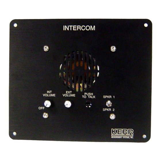
The system consists of three components, the intercom and the remote speaker. The
intercom is powered from12vdc. The remote speaker connects to the intercom output
port through either a bulkhead cable or a cable spool of up to 250' in length.
The remote speaker serves both as a speaker and a microphone.
The intercom comes with connectors for two remote speakers. A switch is provided on
the front panel to select which speaker is in use. One speaker can be installed in the
logging unit near the wireline drum and the other speaker can be placed near the well
head through a 100' – 250' cable reel.
AMLS3A102 INTERCOM SYSTEM SPECIFICATION
INTERCOM SYSTEM
Rev A
Page 1 of 4
JAN 2007
Advertisement
Table of Contents

Summary of Contents for KERR ALS3A102
- Page 1 INTERCOM SYSTEM GENERAL DESCRIPTION This system is designed to mount inside a wireline unit to provide communications between personnel inside the logging cabin and personnel working outside at the wellsite. The system consists of three components, the intercom and the remote speaker. The intercom is powered from12vdc.
- Page 2 ALS3A102 INTERCOM ASSY SPECIFICATIONS DEPTH: 2.72" 6.9 CM WEIGHT: 3 LBS 1.37 KG ALS3A012 INTERCOM CABLE Page 2 of 4 AMLS3A102 INTERCOM SYSTEM SPECIFICATION Rev A JAN 2007...
- Page 3 ALS3A111 SPEAKER ASSY SPECIFICATIONS PIN A = SPEAKER + PIN B = SPEAKER - WIDTH: 6.75" 17.15 CM HEIGHT: 8.53" 21.67 CM DEPTH: 7.92" 20.12 CM WEIGHT: 9 LBS 4.08 KG Page 3 of 4 AMLS3A102 INTERCOM SYSTEM SPECIFICATION Rev A JAN 2007...
- Page 4 OPERATING INSTRUCTIONS Apply power - +12v to pin A and gnd to pin B of power input connector Connect speaker 1 cable to speaker 1 connector on rear of panel. Connect speaker 2 cable to speaker 2 connector on rear of panel Mount speaker 1 on a fixed mount in the unit drum compartment.
Need help?
Do you have a question about the ALS3A102 and is the answer not in the manual?
Questions and answers