
Summary of Contents for Omni PMX
- Page 1 Model PMX Pneumatic Piston Actuator With Integrated Manual Override OPERATION & MAINTENANCE MANUAL OMM-001 REV A...
-
Page 2: Table Of Contents
Rebuilding Model PMX Actuator in the field using Actuator Repair Kit . . . . . . . . . . . . . . . -
Page 3: Introduction
Omni Model PMX Pneumatic Piston actuators are designed to operate surface safety or shutdown valves on oil and gas wellhead, transmission storage, manifold or other application where fail-safe capability is required. Model PMX actuators can be used for land or off shore installations and are engineered to provide reliable service in a variety of operation conditions. -
Page 4: Actuator Operation
OMNI GATE VALVES PREPARED FOR ACTUATOR: Full Assembly Omni offers a complete line of cast and forged body reverse acting slab gate valves prepared for actuator. All Omni valves pre- pared for actuator are designed to be used... -
Page 5: Internal Configuration & Parts List
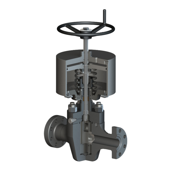
INTERNAL CONFIGURATION Actuator depicted with typical 10,000 psi bonnet. See Note 2 below. Pressure Pressure Relief Valve Inlet / Outlet (ARK) (See Note 1) 1/4” NPT Pressure Inlet / Outlet 1/4” NPT Stem Seal Detail Component Description Component Description Valve Bonnet (see Note 2) Upper Stem Packing Retainer Cylinder Retaining Bolt... -
Page 6: Rebuilding Model Pmx Actuator In The Field Using Actuator Repair Kit
REBUILDING MODEL PMX ACTUATOR IN THE FIELD USING ACTUATOR REPAIR KIT REBUILD Disconnect control pressure supply from actuator port and ensure that the actuator is in the fully relieved position. (Valve fully closed in a failsafe closed application). There should not be any pressure in the actuator. Caution: Quick exhaust valves can trap residual pressure in the actuator. - Page 7 page 7...
-
Page 8: Bonnet To Gate Valve Assembly
BONNET TO GATE VALVE ASSEMBLY Push the male stem down until the lower threaded portion is exposed. Thread gate on to stem. Depending on design this may or may not require installation of a gate nut. Thread gate as far on to the stem as possible and still be able to install the gate pin. The gate pin should be fully captured by the slot in the end of the stem. -
Page 9: Assembly Of Lower Plate Assembly To Bonnet
ASSEMBLY OF LOWER PLATE ASSEMBLY TO BONNET Slide the lower plate retainer ring down over the bonnet shoulder out of the groove to allow the lower plate to move past the bonnet retaining ring groove at the top of the bonnet. Clean and inspect o-ring grooves. -
Page 10: Assembly Of Main Pmx Actuator Assembly
ASSEMBLY OF MAIN PMX ACTUATOR ASSEMBLY Check actuator operating stem for surface finish condition and ID threads. Apply never seize to internal threads. Clean and inspect groves of down stop. Grease thoroughly and install two down stop seal O-rings in the down stop. -
Page 11: Replacement Of Bonnet Seals
REPLACEMENT OF BONNET SEALS With the bonnet neck facing up clean and inspect the packing bore for damage. Carefully check the ID threads for damage. Lightly lube the polypaks and insert in the packing bore with O-ring facing down. Lightly lube both O-rings and install on the ID and OD of the packing retainer. Lube threads of the packing retainer and thread into the bonnet until the flange of the packing retainer stops on the neck of the bonnet. -
Page 12: Setting Gate Valve Drift Shims
SETTING THE GATE VALVE DRIFT Setting the drift can only be accomplished after the bonnet assembly has been installed on the gate valve. All studs and bolts have been torqued with all stem to gate connections completed. Place the gate valve in the vertical position. Remove piston and stem assembly. -
Page 13: Servicing Of Omni Valve Actuator Assemblies & Periodic Maintenance
SERVICING OF OMNI VALVE ACTUATOR ASSEMBLIES Prior to servicing the actuator assembly, it is recommended that this manual be read in its entirety. Should the service technician have any questions or feel that a certain procedure cannot be performed safely, contact Omni Valve for assistance. -
Page 14: Trouble / Probabable Cause / Remedy Table
TROUBLE PROBABLE CAUSE REMEDY Failure at one or more of the following: O- Replace appropriate O-rings or safety. rings, or safety relief valve Accumulation of foreign matter or corrosion Clean areas, relubricate, and replace appropri- between piston and piston housing and/or ate O-rings. -
Page 15: Warranty
In the case of products or parts not wholly of Omni’s manufacture, Omni’s liability shall be limited to the extent of Omni’s recovery from the original manufacturer of such products or parts under its warranty or liability to Omni.
Need help?
Do you have a question about the PMX and is the answer not in the manual?
Questions and answers