
Related Manuals for Magnimage MIG-EC90


Summary of Contents for Magnimage MIG-EC90
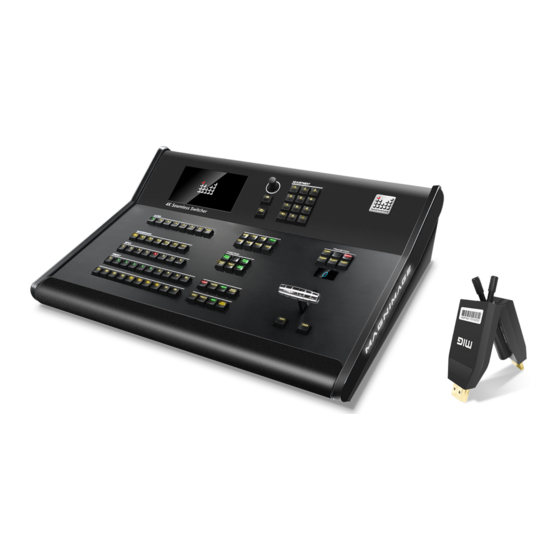
- Page 1 MIG-EC90 Event Console User manual V1.0 Before using this video processor, please read this manual carefully and keep it for reference in the future. △ All-in-one 4K Event Console...
- Page 2 Statement Without the written permission, any unit or individual could not copy, reproduction or translate the book or part of it. Also could not transmit it in any form or any way (electronic, mechanical, photocopying, record or other way) for any business and profitable purpose.
-
Page 3: Table Of Contents
Directory BRIEFS........................1 ............................ 1 RADEMARK CREDIT ..........................1 BOUT THE SOFTWARE ..............................2 EATURES ............................3 XTENDED PORTS ..........................4 AFETY INSTRUCTIONS ............................4 PECIFICATION FUNCTION INTRODUCTION..................5 ................................5 RIEF ............................6 HE FRONT PANEL ............................7 HE REAR PANEL Other....................... 错误!未定义书签。 ...........................8 ECHNICAL SPECIFICATIONS USER MENU...................... - Page 4 PRESET AREA: ....................错误!未定义书签。 TRANSITION AREA................... 错误!未定义书签。 WARRANTY......................49 ..........................49 ACHINE WARRANTY ............................49 WARRANTY...
-
Page 5: Briefs
Briefs Thanks for your purchasing our MIG-EC90 event controller. Do hope you can enjoy the experience of the product performance. The design of the LED video processor conforms to international and industry standards. But if with improper operation, there will be a personal injury and property damage. In order to avoid the danger, please obey the relevant instructions when you install and operate the product. -
Page 6: Features
Features 2 Program output + 1 Multi-preview + 2 AUX outputs 4K×2K@60Hz Program output and AUX output Customized input and output resolution Support HDMI 2.0, DP 1.2 & 12G SDI inputs 8 standard 4K×2K@60Hz input Support expand 2 input modules,each one has 2 inputs ... -
Page 7: Extended Ports
Extended ports The MIG-EC90 is the basic model. Based on this model, it can be extended with more input modules as shown in the following table: Model No. Description Available extended input card Input card... -
Page 8: Safety Instructions
Safety instructions The power input voltage range of the product is 100~240V AC/60HZ,please use the correct power supply accordingly. When you need to connect or pull out any signal or control cables. Please confirm that all the power supply cords have been pulled out ahead. When you need to add hardware device for the machine, make sure all of ... -
Page 9: Function Introduction
Function introduction Brief MIG-EC90 is a 4K seamless switcher which combines input, output, switching and controlling in one machine. Based on its 4K/60Hz 4:4:4 processing technology and matrix design, this switcher is able to manage and switch 4K video freely. -
Page 10: The Front Panel
The front panel Button instruction MENU area Include touch screen, the rotary knob, OK button and return button to adjust parameters and operate menu ADJUSTMENT area Number buttons to adjust parameters LAYER area Choose and operate layer area BKG area Choose and operate BKG area FUNCTION 1~2 area Function area... -
Page 11: The Rear Panel
3- Input 1-4,HDMI 2.0*4 4- Input 5-6,DP 1.2*4 5- Input 7-8,12G SDI*2 6- Multi-preview output 7- LED light and switch 8- Power port and switch 9- LAN:Control the machine with software 10- USB: MIG-EC90 software upgrade Genlock in & out... -
Page 12: Other
Other The fan, power port and switch Technical specifications Standard inputs Port Quantity Resolution HDMI 2.0 (1-4) 4 3840×2160/60Hz and EDID management DP 1.2(5-6) 3840×2160/60Hz and EDID management 12G SDI (7-8) 3840×2160/60Hz... - Page 13 HDMI×1 Remarks:2×2 indicates 2 groups of output and 2 duplicate output ports in each group. Control port RJ45×1 RJ45 interface to control MIG-EC90 USB×1 USB port to upgrade MIG-EC90 GENLOCK IN×1 OUT×1 Genlock port to keep synchronization between multiple units...
-
Page 14: User Menu
User menu Default status introduction After turning on the power of MIG-EC90 event controller, the front panel of the LCD screen will display the opening interface in system start-up procedure, and the LCD screen will display the default status as below. -
Page 15: Main Menu Introduction
Main menu introduction The symbols listed in the below table will appear in the main menu , the specific meanings are as follows: Icon Explanation Return to the main menu or return to the previous menu In the main menu, the user selects and adjusts each item by using the three buttons “OK”... -
Page 16: Main Menu
Numeric keypad description: In addition to any parameters that need to be modified, except press and rotate the knob, touch the left and right arrow keys to operate, it also clicks the corresponding parameter and pops up the numeric keypad on the screen to operate. 0 to 9 represent numbers, : A decimal point 3840 : To exit the numeric keypad mod... -
Page 17: Picture Setting
Picture setting Program output layer setting: Image setting sub menu is used to set this device output layer’s brightness level, Gamma value and the parameter for each layer. Brightness level Open or close this function, range from 0 to 16. Gamma Open or close this function, gamma range from 0.0 to 5.0. - Page 18 Divided into “4000K”, “5000K”, “6500”, “7500K”, ”8200K”, ”9300K”, “10000K”, Layer 1~6 “11500K”, “User”, total 9 options. color Red range 0~225, the default is 128. temperature setting Green range 0~225, the default is 128. Blue range 0~225, the default is 128. Layer 1~4 picture Reset all the layers’picture parameters to default setting.
-
Page 19: Output Setting Menu
Output setting PGM 1,PGM 2, AUX 1, AUX2 output resolution:... - Page 21 HDMI Setting with the receiving part. Note 1: For the MIG-EC90 main output and AUX output, A and B port output resolution is the same. Note 2: The customized may not be a standard format, so some monitor will not...
- Page 22 Input Setting Input source:...
- Page 23 Image crop: HDMI/DP RGB Range...
- Page 24 EDID Configuration EDID can be set for all input signals except SDI, and the corresponding input signal can be selected to enter the EDID configuration menu. EDID Input Key 1 setting The current input that is doing EDID setting HDMI...
- Page 25 H Active Modify the horizontal resolution of EDID V Active Modify the vertical resolution of EDID Reset Reset the EDID parameter Accept Write in EDID parameter H Blank Modify the H Blank of EDID Advanced V Blank Modify the V Blank of EDID Note 1:During EDID setting, the computer display mode should be set to extended mode.
-
Page 26: Input Setting
Layer setting Include MAIN layer and AUX layer. Size/Position Zoom... - Page 27 Layer crop Keying setting...
- Page 29 Boarder effect...
- Page 30 Layer template...
- Page 31 Layer Set the layer parameter, like size/position, zoom, crop, color key, shadow effect, layer scale. Configuration Layer 1~6 Select the layer Close/Open Layer open or close Horizontal & vertical position Set the layer horizontal and vertical position Size/Position Width and height Set the layer width and height Clone the current layer(Please review the notes Layer clone...
- Page 32 A yellow frame will show up, move it to select the color should be remove. Display the RGB value which is RGB value selected Color Color Pixel Edit Change horizontal/vertical Keyer Keyer reading Horizontal/vertical parameter to move the yellow position frame, in order to select the color.
-
Page 33: Save And Load
Save and load... - Page 34 Save a preset Load a preset Background...
- Page 36 Save Preset 1~20 This machine can save 20 presets,two indicator lines at the bottom of each preset number: the left indicate lines that the main output preset has been saved, and the right indicate lines that the AUX output preset has been saved. 1~20 This machine can load 20 presets, the main output presets will be called...
-
Page 37: Communication
Communication IP设置 IP地址 192.168. 1.222 编辑 编辑 网关 192.168. 1. 1 E2-B2-E0-EC-45-17 物理地址 复位 <- 应用... - Page 38 Make the computer to use the upper computer to connect to Communication this switcher through the network by modifying the IP address setting of this processor. Display or modify the IP address of this machine, you can select IP address the number to edit through the knob or OK key, or click the edit key on the right side to enter the number .
- Page 39 MISC Status Info...
- Page 40 Test Pattern...
- Page 41 T-Bar Calibration Factory Reset...
- Page 42 Calibrate the T-Bar Calibration Reset the machine to factory settings ,prompt A.C. Restart after Factory Reset confirming to continue.Then the power off and restart. If you want to upgrade the firmware version, please contact the Note: technical support from Magnimage .
- Page 43 语言/Language English Set the menu language as English 简体中文 Set the menu language as simplified Chinese 繁體中文 Set the menu language as traditional Chinese...
-
Page 44: Misc
Multi-preview introduction After turning on MIG-EC90 switcher and work with a external monitor by the Preview port, you will see the Multi-preview interface as below. PROGRAM PREVIEW OUTPUT INFORMATION AUX OUTPUT AUX2 INPUT AUX1 INPUT PGM RESOLUTION 1920×1080 60.00Hz AUX1 RESOLUTION 1920×1080 60.00Hz AUX2 RESOLUTION 1920×1080 60.00Hz... -
Page 45: Button
The menu system of the product can be set up conveniently and intuitively to meet the user's requirements. The MIG-EC90 event console uses a full color single touch LCD to display the entire user menu. The LCD screen will display the default state if the user has no operation or the operation has timed out. -
Page 46: Menu Area
MENU area: This area contains 2 buttons and a knob that can be pressed:OK、 button and knob. Short press "knob", its function is same as confirm key (OK); When the return key is pressed( ), the menu system will return to the next level in turn until it returns to the default state, or long press to return to the main interface. - Page 47 to return to the superior menu until the default state, or wait for the system timeout, the default state will be returned automatically (in some special interfaces, the system will not automatically return to the default state, such as: screen switching shortcut interface, user mode shortcut interface, test pattern interface, etc.).
-
Page 48: Adjustment Area
ADJUSYMENT area: For setting different parameters. Backspace to delete LAYER area: 1-6 active layers Press CLEAR+layer button:to delete the layer which is selected Note : When the light of LAYER 1-6 turns green , it means the layer is on, otherwise it means the layer if off. - Page 49 BACKGROUND area: Yellow light means selected, green light OFF:Turn off the BKG means saved, and light-off means SAVE:Enter the BKG saving unelected. menu INPUT area: When the light of LAYER 1-6 turns green,it means the layer is on, otherwise it means the layer if off. Yellow means the selected layer, red means the unelected layer.
- Page 50 FUNCTION: SIZE:Enter the layer size/position setting; ZOOM:Enter the zoom setting TOP:Set the current layer to the top BOTTOM:Set the current layer to the bottom FULL: Stretch the current signal to the whole output KEYER:Enter the Keyer setting; MAIN:To set PGM output layer only AUX:To set AUX output layer only Long press SHIFT+TAKE SWAP:PGM and Preview will swap when switching;...
- Page 51 PRESET 区: 1-20 represent the 20 presets. When the button light off, it does not have any preset setting. Green light means it is saved a preset. Yellow light means the preset is selected. Red light means there is no preset. LOAD:Press this button to enter the preset area.
- Page 52 TRANSITION area PREPARE:It's a state indication button,you're Press SHIFT+LOCK able to load presets and lock the all buttons on switch when the button is the machine, including lighting, but if the button T-Bar and once again to quenched, you can't load unlock.
- Page 53 Warranty Machine warranty 24 months from the date of purchase of the user’s invoice. If the user purchase invoice is lost, the 60 days after the production date will be the warranty start date for the product. Non-warranty The machine soaking and collisions produced besmirch or ...
Need help?
Do you have a question about the MIG-EC90 and is the answer not in the manual?
Questions and answers