Table of Contents
Advertisement
Quick Links
Advertisement
Table of Contents

Related Manuals for Seeburg S Series

Summary of Contents for Seeburg S Series
- Page 1 Hardware Manual S-Series Version 1.0 06.10.2022...
-
Page 2: Table Of Contents
S-Series 1 Contents Contents Contents .......................... 2 Foreword .......................... 3 Safety Instructions & Installation ................4 Device Overview ......................5 Front Panel ..........................5 Rear Panel ..........................6 Operation ......................... 7 Connections ..........................7 Start-up ............................ 7 Signal Flow Basics ........................ 8 Using the User Interface ....................... -
Page 3: Foreword
IPS touch display. The DSP contains a very extensive preset library for SEEBURG loudspeakers. The user can also create their own presets for third-party products. The S-Series can be fully operated and monitored remotely via Ethernet. Thanks to the integrated network switch, the network connection can be passed on directly to the next device (daisy chain). -
Page 4: Safety Instructions & Installation
S-Series 3 Safety Instructions & Installation Safety Instructions & Installation ATTENTION! The lightning symbol indicates the presence of possibly uninsulated, dangerous voltages! Read this manual before using the device! When the appliance is installed, the plug inserted into the socket outlet must be easily accessible. -
Page 5: Device Overview
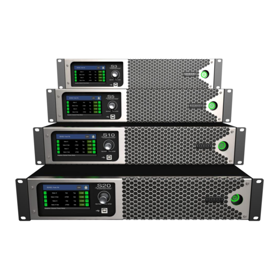
S-Series 4 Device Overview Device Overview 4.1 Front Panel (1) Illuminated operating mode button: Lights up as soon as mains voltage is present. Red: Device in standby, can be addressed via Ethernet. Green: device in operation. To switch the operating mode, hold down the button for one second. (2) Touch Screen: Display information and enter settings. -
Page 6: Rear Panel
S-Series 4 Device Overview 4.2 Rear Panel (1) Signal Input: Neutrik® XLR sockets for analogue or digital (AES3) signals. Sockets 1 and 3 are used for the two-channel AES3 signals. (2) Signal Link: Parallel XLR outputs for daisy-chaining the signal to other amplifiers. (3) Loudspeaker Connectors: Neutrik®... -
Page 7: Operation
S-Series 5 Operation Operation 5.1 Connections Connect the amplifier to a properly grounded AC 90-265V AC outlet. The audio input signal can be either balanced or unbalanced. Balanced signal: pin 1 ground, pin 2 positive signal (hot), pin 3 negative signal (cold). Unbalanced signal: pin 1 ground, pin 2 signal, pin 3 ground. -
Page 8: Signal Flow Basics
S-Series 5 Operation 5.3 Signal Flow Basics The figure shows a configuration example of the amplifiers and in it the basic structure of the signal flow from left (input) to right (output). The physical hardware inputs are assigned to the sources, denoted by the lowercase letters a, b, c and d. -
Page 9: Using The User Interface
S-Series 5 Operation 5.4 Using the User Interface The power amplifiers are operated via a touch-sensitive color display and an endless encoder with a push button function. By touching the individual areas and "buttons" on the display, you can navigate directly to the re- spective function. -
Page 10: Display
S-Series 5 Operation 5.5 Display Pages All essential device settings and information are shown on six display pages: Overview page, Home page, DSP page, Tune page, EQ page and Utility page. 5.5.1 Overview Page Device name, adjustable via the PC software “Lock”... -
Page 11: Home Page
S-Series 5 Operation 5.5.2 Home Page Output channel of the amplifier ICL indicator: Lights up when the amplifier channels protection system is working LIM meter: Shows the extent of the limitation (gain reduction) of the RMS and peak limiters for the loaded loudspeaker OUT meter: Indicates the output signal level relative to the full scale of the loaded loud- speaker T-Meter: Shows the temperature of the amplifier channels als a percentage... -
Page 12: Dsp Page
S-Series 5 Operation 5.5.3 DSP Page Input source Type of input: Selection menu (analog, AES3) Hardware channel of the selected input: Selection menu (1...4) Route In: Input source assigned to the path. Selection menu (a, b, c, d, a+b, c+d) Name of the path: Editable via PC software Group Values: Lights up green if group-wide parameters (EQ, Gain, Delay) are active. -
Page 13: Tune Page
S-Series 5 Operation 5.5.4 Tune Page Input path name User EQ: Lights green when the user equalizer is on. If a user EQ preset is loaded, the name of the preset will appear. Pressing this button takes you to the EQ page. In meter: Displays in input signal level of the path Gain: Input box for adjusting the input level of the path Delay: Input box for adjusting the input delay of the path. -
Page 14: Eq Page
S-Series 5 Operation 5.5.5 EQ Page Input path name User EQ preset name. The preset contains all settings for the seven equalizer filters as well as the set values for path gain and path delay Filter on/off: Displays the status of each filter. Gray = filter off. Green = filter on. Tapping on one of the filters selects it for editing. -
Page 15: Utility Page
HDLM8 and self- powered speaker systems. The latest versions can be found in the download area of the SEEBURG website. Menu bar for calling up the Snapshot, Amplifier, Password, Ethernet and Reset tabs Dimmer: Setting the brightness of the display AutoDIM: Setting the waiting time until the display is automatically dimmed. - Page 16 S-Series 5 Operation 5.5.6.1 Snapshot Tab Save to Lib: Saves the current device state (i.e. all currently set parameters) to a snapshot slot on the device. This can be an empty one or one with an existing preset to be overwrit- ten.
- Page 17 S-Series 5 Operation 5.5.6.3 Password Tab General Password: To activate it, you need to enter and confirm a 4-digit code. If the pro- tection is activated, access to the amplifier via the control panel and the PC software is re- stricted.
- Page 18 S-Series 5 Operation 5.5.6.5 Reset Tab “Process Reset" button resets all parameters and processing of the amplifier to their de- fault state. All settings made and loaded presets are reset. The preset libraries, snapshots, EQ presets stored on the device are retained.
-
Page 19: Technical Specifications
S-Series 6 Technical Specifications Technical Specifications The technical data sheet and further information about possible applications and accessories can be found on the Internet at www.seeburg.com. -
Page 20: Declaration Of Conformity
DIN EN 60065 DIN EN 55103-1:1996, classes E1 to E4 DIN EN 55103-2:1996, classes E1 to E4 Issuer of this declaration: Winfried Seeburg, SEEBURG acoustic line GmbH Place, Date: Senden, 01.06.2022 Authorized signature: ____________________________________________ The appendices are part of this declaration. This declaration certifies compliance with the guide- lines mentioned, but does not include any guarantee of properties. - Page 21 All specifications are current at the time of publishing but are subject to change. Subject to errors in the description. All SEEBURG acoustic line products are intended for professional use only. Dante is a registered trademark of Audinate Pty Ltd.
Need help?
Do you have a question about the S Series and is the answer not in the manual?
Questions and answers