Advertisement
Cyclic Timer
kits
Cyclic timer circuit with programmable relay ON
time and relay OFF time. It can operate in two
modes - seconds and minutes with a setting range
of 1 to 99.
Circuit description
Electrical diagram of the timer is shown in Figure 1.
The device must be supplied with 12 VDC fed to the
ZAS connector. This can be any 12 V power supply
with a current capacity of not less than 200 mA. The
U1 stabiliser provides the +5 V voltage and capacitors
C1...C4 ensure its proper filtration. Operation of the
device is controlled by an Attiny26 microcontroller
timed by an internal clock signal. Status of the unit is
shown on a dual seven-segment display with a
common anode. The cathodes of the 2-digit
multiplexed LED display are connected via current-
limiting resistors R5-R12 to ports PA0-PA7. The role of
the keys that switch on the power supply to the
displays is performed by transistors T1 and T2,
controlled from ports PB3 and PB4.
The LED ON jumper, or rather the absence of it, allows
the displays to be switched off for the duration of the
circuit operation. For setting purposes, the system is
Specifications
• two operating modes: seconds and minutes
• time setting from 1÷99 in 1-step increments
• operating status indicated on two switchable LED
displays
• output circuit - relay NC / NO contacts
• supply: 12 VDC
• board size: 95×37 mm
equipped with 2 buttons labelled S1 and S2. Signals
from the buttons are routed to ports PB0 and PB1 -
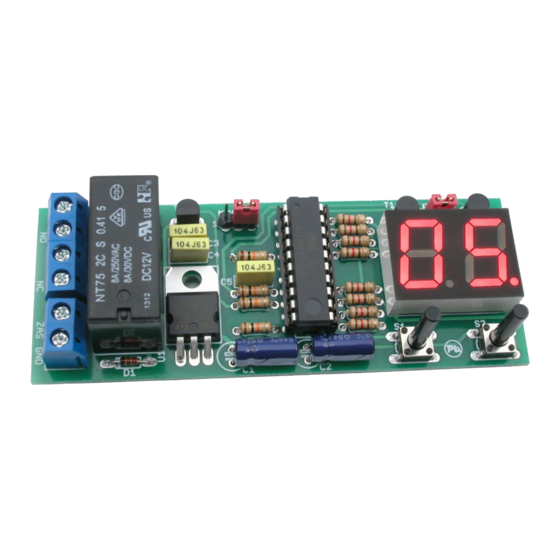
the active level is logical '0'. Mounting diagram of the
timer is shown in Figure 2, it is mounted on
a small, double-sided printed circuit board measuring
36 mm×94 mm, using through-hole components.
Assembly is typical and should not cause any
problems, and a system assembled from working
components will work correctly straight away. To
program the relay OFF time, press and hold the S1
button for approximately 3 seconds. After a while, the
lower segments of the display will start flashing. You
can now release the button and using the S1 and S2
buttons, increase or decrease the flashing value shown
on the display. Once the required time has been set,
press and hold the S1 button again. To set the relay
ON time, press and hold the S2 button, this will be
signalled by the upper segments of the displays
PDF
DOWNLOAD
ASSEMBLY DIFFICULTY
1
Advertisement
Table of Contents

Related Manuals for AVT 1820

Summary of Contents for AVT 1820
- Page 1 Cyclic Timer kits DOWNLOAD ASSEMBLY DIFFICULTY Cyclic timer circuit with programmable relay ON Specifications time and relay OFF time. It can operate in two • two operating modes: seconds and minutes modes - seconds and minutes with a setting range •...
- Page 2 blinking. Changes are made in the same way as switched off for the duration of the unit operation by when setting the switch OFF time using the S1 and S2 removing the LED_ON jumper. It is important to be buttons. Once the correct value has been set, press aware that timekeeping can be subject to a degree of and hold S2 again to complete the programming inaccuracy, particularly when working in the minute...
- Page 3 AVT SPV reserves the right to make changes without prior notice.Installation and connection of the appliance not in accordance with the instructions, unauthorised modification of components and any structural alterations may cause damage to the appliance and endanger persons using it. In such a case, the manufacturer and its authorised representatives shall not be liable for any damage arising directly or indirectly from the use or malfunction of the product.
- Page 4 Notes...
Need help?
Do you have a question about the 1820 and is the answer not in the manual?
Questions and answers