Advertisement
Quick Links
1.Introduction:
It is an 76.0MHz-108.0MHz Wireless FM Radio Receiver Stereo DIY Kit. It is a very
mini rechargeable radio that users can carry and use anytime, anywhere to receive the
latest news.
2.Feature:
1>.Support 76Hz-108MHz receiver frequency
2>.Built-in rechargeable lithium battery and charging circuit
3>.High sensitivity, low noise, strong anti-interference ability
3.Parameter:
1>.Product Name:GS1299 FM Radio Receiver DIY Kit
2>.Work Voltage:DC 3.70V~4.2V
3>.Output channel:Dual channel stereo
4>.Frequency:76.0MHz~108.0MHz
5>.Power indicator: Blue
6>.Charging indicator: Red
7>.Charged indicator: Blue
8>.Output type: AUX output (connect headset)
9>.Work Temperature:-40℃~85℃
10>.Work Humidity:5%~95%RH
11>.Size(Installed):67x51x20mm
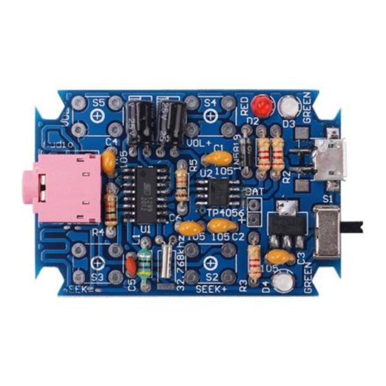
4.Component List:
NO. Component Name
1 GS1299 FM Receiver
2 TP4056 Lithium Battery Charging IC
3 AMS1117-3.3
4 Metal Film Resistor
5 Metal Film Resistor
6 Inductor
7 1N5819 diode
8 Red LED
9 Blue LED
10 Crystal oscillator
11 Ceramic capacitor
12 Monolithic Capacitor
13 Electrolytic Capacitor
14 SK-12D07 Switch
15 Black Button
16 USB Micro Socket
17 AUX Audio Socket
18 3.7V 250mAh Lithium Polymer Battery
19 Acrylic Board
GS1299 FM Radio Receiver DIY Kit
ICStation GS1299 FM Radio Receiver DIY Kit
PCB Marker
U1
U2
U3
R1,R2,R3
R4,R5
L1
D1
D2
D3,D4
Y1
C5
C1,C2,C3,C4,C6
C7,C8
S1
S2,S3,S4,S5
J2
J3
BAT+,BAT-
1
Parameter
QTY
SOP-8
1
SOP-16
1
SOT-223
1
2.2Kohm
3
10Kohm
2
47uH
1
DO-41
1
3mm
1
3mm
2
32.768KHz
1
22pF
1
0.1uF 104
5
47uF
2
1P2T
1
6*6*12mm
4
SMD
1
1
50*20*3mm
1
6
Advertisement

Subscribe to Our Youtube Channel
Related Manuals for ICStation GS1299

Summary of Contents for ICStation GS1299
- Page 1 GS1299 FM Radio Receiver DIY Kit ICStation GS1299 FM Radio Receiver DIY Kit 1.Introduction: It is an 76.0MHz-108.0MHz Wireless FM Radio Receiver Stereo DIY Kit. It is a very mini rechargeable radio that users can carry and use anytime, anywhere to receive the latest news.
- Page 2 GS1299 FM Radio Receiver DIY Kit 20 M3*10mm Copper Pillar 21 M3*8mm Screw 22 Nut 23 PCB 55*3.7*1.6mm Note:Users can complete the installation according to the PCB silk screen and component list. 5. Schematic Diagram: 6.Note: 1>.Headphone must be connected as it is also FM antenna.
- Page 3 2>.Step 2: Randomly choose a pad on the PCB, and then melt the solder on this pad. 3>.Step 3: Fix GS1299 : Use a soldering iron to melt tin on the pad just now and hold GS1299 with tweezers in the other hand to place/press on U1 to prevent movement. Take care to match and align each pads.
- Page 4 GS1299 FM Radio Receiver DIY Kit 19>.Step 19: Install 1pcs 3.5mm AUX Audio Socket at J3. 20>.Step 20: Install 4pcs 6*6*12mm Black Button at S2,S3,S4,S5. 21>.Step 21: Install 3.7V 250mAh Lithium polymer battery. Red wire connect to BAT+ pad and black wire connect to BAT- pad.
- Page 5 GS1299 FM Radio Receiver DIY Kit...
- Page 6 GS1299 FM Radio Receiver DIY Kit...
- Page 7 GS1299 FM Radio Receiver DIY Kit...
- Page 8 GS1299 FM Radio Receiver DIY Kit...
- Page 9 GS1299 FM Radio Receiver DIY Kit...
- Page 10 GS1299 FM Radio Receiver DIY Kit...
- Page 11 GS1299 FM Radio Receiver DIY Kit...
- Page 12 GS1299 FM Radio Receiver DIY Kit...
- Page 13 GS1299 FM Radio Receiver DIY Kit...
Need help?
Do you have a question about the GS1299 and is the answer not in the manual?
Questions and answers