
Summary of Contents for Mentor radio M2115RCU Series
- Page 1 Wireless Solutions for Advancing Communications M2115RCU RADIO CONTROLLER OWNER’S MANUAL Phone: (216) 265-2315 Fax: (216) 267-2915 www.mentorradio.com...
- Page 2 MARINE: M2115RCU-M Mentor Radio produces a family of radio control units, also known as, Pilot Controlled Lighting (PCL), or Pilot Activated Lighting (PAL) systems. This manual covers both aviation and marine band versions for both the 25kHz and 8.33kHz channel spacing. The aviation band version is a VHF radio that operates from 118-137MHz and the marine version is a VHF radio that operates in the frequency range from 155-157MHz.
-
Page 3: Table Of Contents
Wireless Solutions for Advancing Communications Table of Contents 1. Safety Warnings 2. Component Layout 3. Controls Layout 4. Basic Features 5. Theory of Operation 6. General System Operation 7. Dip Switch Configuration Options 8. Installation 9. Testing, Programming and Adjustments 10. -
Page 4: Component Layout
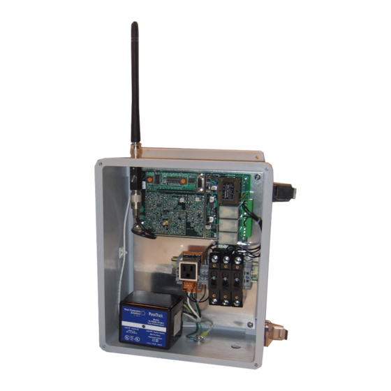
Wireless Solutions for Advancing Communications Component Layout (Includes optional items) Reset Switch Test Switch Communications Port Antenna Lightning Protector (opt) Sensitivity Pot NEMA 4 Enclosure (opt) DIN Rail with AC power plug and CB's (opt) AC Line Lightning Protector (opt) Phone: (216) 265-2315 Fax: (216) 267-2915 www.mentorradio.com... -
Page 5: Controls Layout
Wireless Solutions for Advancing Communications Controls Layout Communications Port (3) Test Button Reset Button (1) Power Switch (4) Sensitivity Potentiometer (5) GND (10) Antenna Input – BNC (6) 7 Click Relay (7) 3 Click Relay (9) 5 Click Relay (8) Phone: (216) 265-2315 Fax: (216) 267-2915 www.mentorradio.com... -
Page 6: Basic Features
Wireless Solutions for Advancing Communications Basic Features Channel Spacing: 25kHz or 8.333 kHz Synthesized Tuning - Customer programmable. Utilizing a standard DB-9 serial cable (included) use your PC to program the operating frequency using custom PC software. Password authentication required to change operating frequency for increased security and to prevent inadvertent changes. -
Page 7: Theory Of Operation
Wireless Solutions for Advancing Communications Theory of Operation The M2115RCU radio control unit consists of a radio receiver and a microprocessor-based decoder/controller assembly. The receiver detects microphone “clicks”—short radio transmissions when a user presses the push-to-talk (PTT) switch on an external VHF radio. The decoder operates relays according to the patterns of clicks. -
Page 8: Dipswitch Configuration Options
Wireless Solutions for Advancing Communications During any time-out period, another series of microphone clicks may be transmitted, decoded and the corresponding relays are energized provided the relay “deactivate disable dip switch” (switch 5) is not enabled. The configuration of the following sections define how the unit will perform. Dipswitch Configuration Options To aid in the configuration, there is a visual aid in the PC software included to allow viewing the switches that are set and the interpretation of their behavior. -
Page 9: Installation
Wireless Solutions for Advancing Communications Mutually Exclusive Configuration (Dipswitch 6 Off) This mode is programmed to allow only one of the relays to be energized at any one time. For example, as before, the first click starts the configured “Window” timer. (3 seconds or 5 seconds). If 3 clicks are received before the “Window”... - Page 10 Wireless Solutions for Advancing Communications Choose a proper site*: The M2115RCU may be installed either indoors or outdoors. Considerations about antenna placement, power input availability and relay connection requirements should be taken into consideration when selecting a suitable installation location. (*Note: See installation instructions for each model listed for individual recommendations.) NOTE: When the M2115RCU is mounted outside, a location should be selected so that the antenna...
- Page 11 Wireless Solutions for Advancing Communications M2115RCU-ALC Aluminum case with external terminal boards on the rear and an antenna input BNC connector on the front. 1. Remove the four case screws and mount the case to an appropriate mounting fixture so that the unit is secure before connecting wires.
- Page 12 Wireless Solutions for Advancing Communications M2115RCU-STC 1. Install case to appropriate mounting fixture. 2. Install control relay and power wires through the NEMA case and attach to green PCB mating connector as follows. Pin 1: K1-NO Pin 2: K1--C Pin 3: K1-NC Pin 4: K2-NO Pin 5: K2-C Pin 6: K2-NC...
-
Page 13: Testing, Programming And Adjustments
Wireless Solutions for Advancing Communications When the M2115RCU is mounted outside, a location should be selected so that the antenna is not “shadowed” by buildings or other obstructions in the direction from which aircraft may approach. For maximum radio range, mount the antenna as high as practical. For outdoor operation, use of an optional NEMA enclosure is required. - Page 14 Wireless Solutions for Advancing Communications Testing using radio: Press the microphone button 3, 5 & 7 times each to verify relays energize and de-energize according to dip switch configuration settings. (Allow time for window LED to extinguish before starting next series of clicks.) Testing using Test button on M2115RCU: 1.
- Page 15 Wireless Solutions for Advancing Communications Programming The programming procedure is required to change the operating frequency. Once set this should not need to be changed, but may be viewed to ensure correct programming of the operating frequency. The configuration procedure is available to aid customers when changes to the dip switch settings are desired or needed.
- Page 16 Changing the Frequency (8.333 KhZ Channel Spacing) The software is a self-contained executable file that can be run from any directory in a computer storage system. (NOTE: the software will program any Mentor Radio RCU frequency and not only 8333Hz versions.) Make sure that the “COM”...
- Page 17 Wireless Solutions for Advancing Communications 6. Press the “Put in Program Mode” button. (Figure 2) Figure 2 7. Enter the desired frequency in the Frequency box. Frequency must be entered in Hz format. There should be 9 digits for each frequency. (Figure 3) Figure 3 Phone: (216) 265-2315 Fax: (216) 267-2915 www.mentorradio.com...
- Page 18 Wireless Solutions for Advancing Communications 8. Press the “Send” button. (Figure 4) Figure 4 The M2115RCU will change frequency right after the ”Send” button is pressed. Multiple frequencies can be entered, but only the last one entered before the M2115RCU is turned off will be remembered. 9.
- Page 19 Wireless Solutions for Advancing Communications Configuration This section describes how the software may aid the customer in selecting the physical dipswitch settings to ensure the controller is operating as expected. This procedure may be used with the 25 kHz software whether the controller is connected to the PC or not. Using the software without the controller allows the user to test a new dipswitch setting without actually affecting the actual controller relays or stressing the connected control circuits.
-
Page 20: Periodic Maintenance
Wireless Solutions for Advancing Communications Adjustment Setting the Sensitivity Potentiometer (5) requires no tools. To adjust the sensitivity potentiometer, (5). simply turn the shaft of the potentiometer (5) counter-clockwise (CCW) to increase sensitivity and clockwise (CW) to decrease sensitivity. Periodic Maintenance Periodic maintenance/inspection is recommended. - Page 21 Wireless Solutions for Advancing Communications Spurious Operations Occasional spurious (unexpected) operations are nearly inevitable. Usually the spurious operations are not caused by a defect in this equipment. For airport lighting, some possible causes of these “spurs” include: 1. An aircraft intending to operate lights at another airport accidentally transmits on the wrong frequency, or both airports use the same frequency for light control.
-
Page 22: Troubleshooting
Wireless Solutions for Advancing Communications Troubleshooting Problem: Pilot cannot turn on runway lights from the air. Pilot can turn on lights when aircraft is on the ground. Solution: Adjust sensitivity potentiometer. Problem: Unit Inoperative. Is Status LED blinking? Yes: Test without computer (See instructions below). 1. - Page 23 Wireless Solutions for Advancing Communications Items 8 and 9 are for installations that have lightning protection installed. Problem: Potential lightning strike. Solution: If there is a lightning strike on the antenna. Replace the gas discharge tube and inspect all wires, ground wire, coax and antenna for damage. Problem: Potential lightning strike on power source.
- Page 24 Wireless Solutions for Advancing Communications To establish that contacts on a relay are not operating correctly, observe the associated LED (red, green, yellow). If the LED lights up, but the controlled lights do not respond, connect a jumper across the relay contacts. If the lights do respond as expected, the relay may be defective. Note that in many installations there will be another external relay between the decoder relay and the lights.
- Page 25 Wireless Solutions for Advancing Communications Phone: (216) 265-2315 Fax: (216) 267-2915 www.mentorradio.com...
- Page 26 Wireless Solutions for Advancing Communications Phone: (216) 265-2315 Fax: (216) 267-2915 www.mentorradio.com...
- Page 27 Wireless Solutions for Advancing Communications Phone: (216) 265-2315 Fax: (216) 267-2915 www.mentorradio.com...
- Page 28 Wireless Solutions for Advancing Communications Phone: (216) 265-2315 Fax: (216) 267-2915 www.mentorradio.com...
- Page 29 Wireless Solutions for Advancing Communications Phone: (216) 265-2315 Fax: (216) 267-2915 www.mentorradio.com...
- Page 30 Wireless Solutions for Advancing Communications Phone: (216) 265-2315 Fax: (216) 267-2915 www.mentorradio.com...
-
Page 31: Optional Accessories
Wireless Solutions for Advancing Communications Optional Accessories 1. Enclosure/ Case NEMA 4 (outdoor use) Fiberglass enclosure Steel enclosure Aluminum case (no DIM rail, no lightning protector, indoor use only) 2. Antenna lightning protector 3. AC line lightning protector 4. DIN rail mounted components 5. -
Page 32: Limited Warranty
Wireless Solutions for Advancing Communications LIMITED WARRANTY Your Mentor Radio equipment is warranted to the original consumer purchaser only, for one full year, to be free from defects in materials and workmanship under normal use. This warranty does not include damage to the product resulting from accident or misuse.
Need help?
Do you have a question about the M2115RCU Series and is the answer not in the manual?
Questions and answers