
Summary of Contents for Farr camfil STR2
- Page 1 Integrated Dust Collector and Solenoid Controller Model STR2-6 Model STR2-6-A22 User’s Manual Installation, Operation and Maintenance Certified ATEX Zone 2 and 22: II 3D Ex mD IP65 A22 T 90 Deg C II 3G Ex mb IP65 T5...
-
Page 2: Table Of Contents
CONTENTS GENERAL DESCRIPTION...................... 3 ATEX CERTIFICATE........................4 GENERAL CHARACTERISTICS..................... 5 FUNCTIONAL CHARACTERISTICS..................5 OPERAION...…………………………………………………………………………………….6 ACCESSING CONTROLS AND REGULATORS ..............7 ELECTRICAL CONNECTIONS....................9 SPECIAL WARNINGS FOR ATEX NORMATIVE.............. 10 Precautions to be taken to avoid that certain ignition sources become active:....... 10 Installation .......................... -
Page 3: General Description
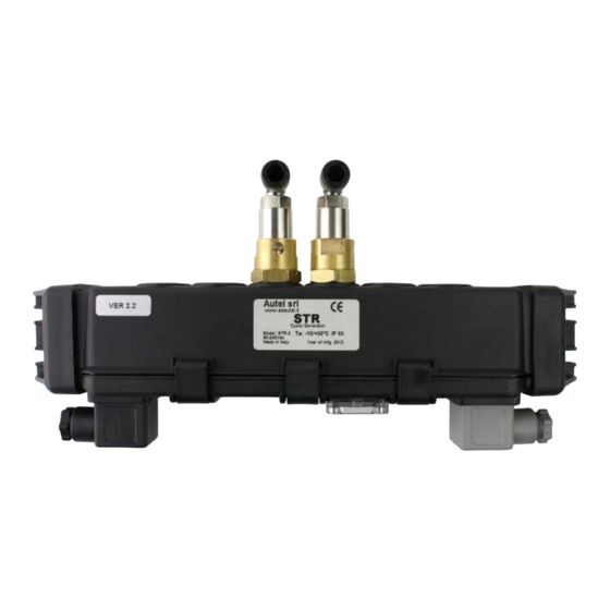
GENERAL DESCRIPTION This device is an economical dust collector control timer. It is available with 2, 4, or 6 solenoids that will activate the dust collector diaphragm valves. The solenoids connect to the diaphragm valves with ¼” od poly tubing. This control is simple to operate and is suitable for small dust collectors. -
Page 4: Atex Certificate
ATEX CERTIFICATE (if applicable) This series of devices are certified according to the European normative ATEX (94/9/EC). They have been designed and built to be used in environments considered potentially explosive because of combustible gas or dust suspended in the air.The degree of protection offered against the dangers of explosion is shown in the CE-ATEX labeled on the instrument. -
Page 5: General Characteristics
GENERAL CHARACTERISTICS Enclosure IP65 – Totally protected from dust ingress and protected from low pressure water jets. Black Polyamide / glass sphere composite Power Supply 90 – 240 Vac 50 /60 Hz 24 Vac 50/60 Hz or Vdc +/- 10% (optional Power 25 W Working Temperature 14 to 122 F (-10 to + 50C) -
Page 6: Operaion
Operation The STR2-6 timer sequentially activates internal solenoid valves based on the on and off timer settings. These valves are connected to the primary diaphragm valves on the filter with ¼” od tubing. The controller has two 43650 DIN connectors. One connector is for power and ground and the other is for differential pressure control and initiating the shut down cycle. -
Page 7: Accessing Controls And Regulators
WARNING: The DIN inputs for on demand cleaning and/or the shut down cycle are not used the Din cover must be installed and the wire inlet must be sealed with a 6 – 8 mm cap (supplied) to maintain the electrical and ATEX ratings. Lock out power before working on electrical connections to this device. - Page 8 Table II: Off time adjustment Pause Position (sec) The pulse off time is controlled by a rotating commutator per the positions in table 2. The rheostat trimmer is used to set the on time. Min: 80 milliseconds Max: 650 milliseconds Adjust on time so that you hear a sharp pulse similar to a shotgun blast.
-
Page 9: Electrical Connections
ELECTRICAL CONNECTIONS The power supply DIN connector is black and contains three contacts for Line, Neutral, and Ground. This DIN connector has 3 contacts to differentiate it from the control DIN connector and avoid interchanging of the connectors. The controller contains a bridge rectifier and will accept AC or DC voltage. -
Page 10: Special Warnings For Atex Normative
WARNINGS: • Always connect the device to ground • Do not swap the DIN connectors. If a connector requires excessive force check that they are not swapped. • To maintain the IP65 protection level of the DIN connectors follow the following recommendations: o Disconnect and lock out power to the controller. -
Page 11: Maintenance
• Press-cables that don’t compromise the IP protection level declared for the enclosure must be used. • For all the device models it is always advisable to install outside of the danger zone, with zener barriers on the power-supply lines, in order to limit the maximum energy of possible sparks.
Need help?
Do you have a question about the camfil STR2 and is the answer not in the manual?
Questions and answers