Table of Contents
Advertisement
Quick Links
Advertisement
Table of Contents

Subscribe to Our Youtube Channel
Summary of Contents for Whadda WSAH8098
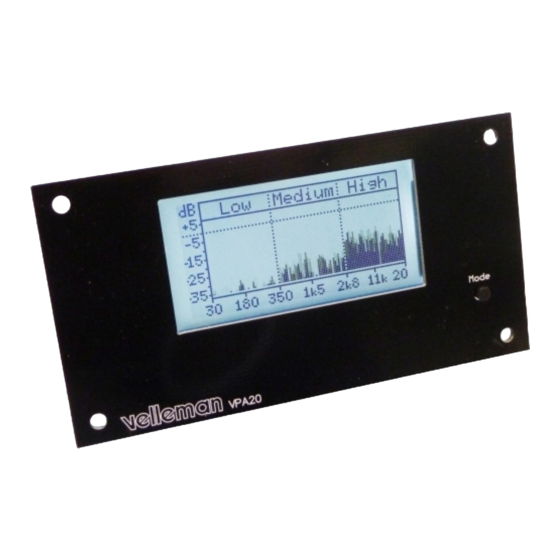
- Page 1 ILLUSTRATED ASSEMBLY MANUAL AUDIO ANALYZER WSAH8098 whadda.com...
-
Page 2: Specifications
Specifications Features - measure: - power measurement into 2, 4 or 8 ohms + bridged amp » peak power (fig.1) option » RMS power (fig.2) - range: 300mW to 1200W @ 2 ohms » mean dB (fig.3) - sensitivity: -34dBu (15.5 mVrms) »... - Page 3 DO NOT BLINDLY FOLLOW THE ORDER OF THE COMPONENTS ONTO THE TAPE. ALWAYS CHECK THEIR VALUE ON THE PARTS LIST! - 3 -...
-
Page 4: Resistor Color Code
RESISTOR COLOR CODE Tolerance DIGITS Multiplier 4th stripe stripe Black 10K OHM 100K OHM x 10 Brown +/- 1% +/- 5% x 100 digit digit digit digit Orange x 1 000 digit multiplier multiplier tolerance x 10 000 Yellow tolerance 0.6 W x 100 000 Green... -
Page 5: Jumper Wire
Construction Construction The audio analyzer consist of three parts: the basic module, the display module and the front panel. If required you can mount this kit into a housing, panel, ... In this case use the display gap as a marker reference. First we assemble the basic module. -
Page 6: Voltage Regulator
Construction Voltage regulator Pin header VR1 : LM317 Ceramic Capacitors C... C1 : 100nF (104) C2 : 100nF (104) C3 : 100nF (104) C9 : 4.7nF (472) C10 : 470pF (471) C... C11 : 47pF (47) ... -
Page 7: Push Button
Construction Electrolytic Capacitor IC’s Watch the polarity! C4 : 10µF C5 : 10µF C6 : 220µF C7 : 220µF C8 : 4,7µF Watch the position of the notch! C14 : 4,7µF Board-to-wire connector IC1 : MCP6002-E/P ... -
Page 8: Display Module
Construction Display module Follow these steps for correct soldering Capacitors SMD components. C1 : 1µF C6 : 1µF C2 : 1µF C7 : 1µF C3 : 1µF C8 : 1µF C4 : 1µF ... - Page 9 Assembly Assembly 1. Roughen the 4 bolts with a knife, a fi le or some abrasive paper so it will be easier to solder them to the front panel. 2. Assemble the unit but do not yet tighten the bolts (fi g.1). 3.
- Page 10 4. Solder 2 diagonal bolts to the front panel. Check if the display is still centred in the cut-away. Solder the remaining 2 bolts (fi g. 3). 5. Now, fi x the whole unit using the 4 nuts and remove the tape.
- Page 11 Connection Connection EX. “BRIDGED” AMPLIFIER OR HIGH POWER RADIO DO NOT CONNECT TO K8098 Bridged Amplifi er orange Speaker OUT Do not connect ! orange +12V battery yellow brown Signal IN Activate BRIDGED function battery in setup-menu GND / chassis High-Power car radio...
- Page 12 Connection Ex. Connected to speaker output Ex. Connected to speaker output yellow Speaker OUT orange Amplifi er ex. K8081 12V battery brown yellow orange 12V battery brown HINT FOR STEREO CONNECTION SIGNAL From amplifi er or TO K8098 LINE OUT...
- Page 13 Short press on the ‘mode’ button: selecting a meter-display. Long press on the ‘mode’ button: opening the set-up menu. Set-up menu - Speed: refreshing the screen (Fast - Mid - Slow) - Impedance: “2”, “4” or “8” ohms for speaker output power calculation, in case the unit is connected to speaker output.
-
Page 14: Advanced Settings
Advanced settings Language: UK / NL / FR / DE / ES Contrast : choose a contrast between 1 - 20 Reverse video: normal or reverse display True mean: Yes or no. If ‘no’ is selected then the display gives the integrated “peak values”. - Page 16 Diagram AVDD AVREF CON BTWM4 1N4007 LM317 47mH 100n 100n 10µF 220µF/25V 10µF 220µF/25V 100n AVDD LCD1 MCLR IC1B AN12/RP12/CN14/RB12 TCK/SCL1/RP8/CN22/RB8 220K AN11/RP13/CN13/RB13 AN10/RP14/CN12/RB14 TLV272 4µ7 AN1/VREF-/CN3/RA1 AN9/RP15/CN11/RB15 TDO/SDA1/RP9/CN21/RB9 PGEC2/TMS/RP11/CN15/RB11 PGED1/AN2/C2IN-/RP0/CN4/RB0 180K PGED2/TDI/RP10/CN16/RB10 PGEC1/AN3/C2IN+/RP1/CN5/RB1 AN4/RP2/CN6/RB2 AN0/VREF+/CN2/RA0 AN5/RP3/CN7/RB3 SOSCI/RP4/CN1/RB4 PGED3/ASDA1/RP5/CN27/RB5 AVREF SOSCO/T1CK/CN0/RA4 PGEC3/ASCL1/RP6/CN24/RB6 OSCI/CLKI/CN30/RA2...
- Page 17 Leds and how to use them Never connect leds in parallel Leds feature a specifi c voltage drop, depending on type and colour. Check the datasheet for exact voltage drop and rated current ! How to Calculate the series resistor: Example: operate a red led (1.7V) on a 9Vdc source.
- Page 18 Modifications and typographical errors reserved. © Velleman Group nv, Legen Heirweg 33 - 9890 Gavere (België) WSAH8098 - 10082021...
Need help?
Do you have a question about the WSAH8098 and is the answer not in the manual?
Questions and answers