Advertisement
Quick Links
Providing Mobility for
the Physically Challenged
Since 1952
Back Up Steering System
2001 - Present
Daimler-Chrysler Mini Vans
Installation Manual and Owner's Guide
37 Daniel Rd. West, Fairfield, NJ 07004-2521 • 973-808-9709 • FAX 973-808-9713 • E-MAIL: sales@drivemaster.net
DCBUS Rev 03-09
Advertisement

Summary of Contents for Drive Master Back Up Steering System
- Page 1 Providing Mobility for the Physically Challenged Since 1952 Back Up Steering System 2001 - Present Daimler-Chrysler Mini Vans Installation Manual and Owner’s Guide 37 Daniel Rd. West, Fairfield, NJ 07004-2521 • 973-808-9709 • FAX 973-808-9713 • E-MAIL: sales@drivemaster.net DCBUS Rev 03-09...
- Page 2 Mobility Dealer and Installing Technician Congratulations, You have just purchased the finest, most reliable Back-Up Steering system manu- factured. We are offering a 3 year/36,000 mile manufacturer’s components warranty – see warranty pages for details. Please read and reread these instructions as im- provements have been made to make your installation easier and the components last longer.
- Page 3 DEALER WARNINGS The back-up system should not be used to take the place of the fac- tory power steering system. Route all hoses to prevent rupture or chafing of back-up and factory lines and keep away from hot exhaust & manifold components. Only trained and certified technicians can install Drive-Master back- up systems, otherwise the warranty will be void.
- Page 4 Back-Up Steering System Operation for the owner/user The Drive-Master Back-Up Steering system is designed to provide emergency power steering in the event of engine stall or OEM power steering failure. You have a Back-Up Steering System because your OEM steering is modified to low or no effort. The Drive- Master back-up steering pump will automatically activate when the OEM power steering flow is disrupted.
- Page 5 DRIVE-MASTER BACK-UP STEERING SYSTEM LIMITED PARTS ONLY WARRANTY DRIVE-MASTER warrants that the parts of your new Back-Up Steering System are free from defects in materials or workmanship for a period of 3 years or 36,000 miles from date of first retail purchase, whichever occurs first. Return of Warranty Registration Card Your return of the attached Warranty Registration Card within 10 days of your purchase is a condition of per- formance under this Limited Parts-Only Warranty.
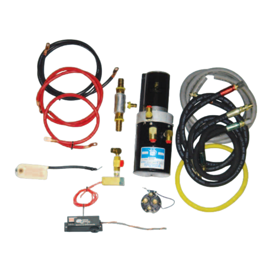
- Page 6 Parts List Back-Up Steering Kit 2001 and up Daimler Chrysler Minivans 1 Back-Up Steering pump and motor assembly 1 Back-Up Steering solenoid 1 24" 2 Gauge Red with lugs - used between solenoid and the battery 1 48" 2 Gauge Red with lugs - used between solenoid and the back-up Steering pump 1 65"...
- Page 7 Open hood for access to engine compartment. Disconnect the OEM battery. Remove both headlights. Remove the front bumper clip. Remove the wiper arms. (2001 - 2007 only) Remove the wiper cowl. (2001 - 2007 only) Disconnect the wiper fluid tube and the wiper power plug, then remove the lower wiper cowl assembly.
- Page 8 10. Locate the center point on the top of the front bumper and mark it. This will be the center point for the back-up steering pump bracket. 11. Make sure to protect the radiator while drilling and bolting the back- up steering pump.
- Page 9 14. Remove the OEM low pressure hose located between the OEM power steering reservoir and the OEM low pressure line going to the power steering cooler. 15. Install the provided 3/8" PUSH-LOK hose between the OEM reser- voir and the OEM low pressure cooler line. #6 Hose clamps should be used to secure the PUSH-LOK hose.
- Page 10 16. The T assembly can now be installed as shown in this picture. (Also see step #18.) This picture is to demonstrate location of the T assem- bly. Cut 3" out of the OEM fill line and insert the T assembly with the 1/2"...
- Page 11 18. Attach the 1/2" gray PUSH-LOK hose to the T fitting. IMPOR- TANT!!!! This 1/2" PUSH-LOK line must slope downward toward the back-up steering pump. This must be a continuous straight slope, no rises as it will trap air in the system. Slope downward towards bus pump T insert with push lok hose...
- Page 12 19. Attach the remaining side of the 1/2" PUSH-LOK hose to the back- up steering pump’s 1/2" barbed fitting. 20. Install the 33" high pressure hose using Teflon tape. Install one end into the high pressure output side of the back-up steering pump. Back-up Steering Pump with hoses...
- Page 13 Shuttle-flow Valve Assembly Shuttle valve and flow sensor assembly...
- Page 14 21. Insert the remaining end of the high pressure line from the back-up steering pump into the shuttle valve-flow sensor input fitting. High pressure line attached to shuttle-flow assembly...
- Page 15 22. Locate the OEM high pressure line from the OEM power steering pump. Remove the retaining clamp located on the back side of the engine block. This 13 mm bolt can be removed from under the vehi- cle with extensions and a swivel socket. 23.
- Page 16 25. Clean the end of the cut. Bend the OEM line into more of a U-shape. Use EXTREME CAUTION not to kink the line. 26. Place the line in a vice and slightly twist the line so it will lay flat on the bench.
- Page 17 27. Locate the 25" BLUE High pressure hose and attach the compression side to the OEM high pressure line. 28. Make sure the O-ring is still present and reinstall the modified OEM high pressure line with the line facing upward and toward the front of the vehicle.
- Page 18 29. Locate the 54" RED High pressure line and attach the compression side to the input line going to the rack. View from under vehicle High pressure line to rack...
- Page 19 30. Apply Teflon tape on the RED marked high pressure line and install into the shuttle valve marked with RED. 31. Apply Teflon tape on the BLUE marked pressure line and install into the flow sensor. High pressure line installed...
- Page 20 32. Add the ground strap from the negative battery terminal to a cleaned ground point. 33. Mount the back-up steering solenoid as shown, utilizing the OEM hole in the cross member and the screws provided. Attach ground strap...
- Page 21 34. The bracket for the shuttle-flow valve assembly needs to be secured under the hood prop bracket. Use the 1/4"-20 bolt and lock nut to through bolt the hood prop bracket with the shuttle-flow bracket (studded bracket). 35. Install the top plate with the bolts provided to secure the shuttle-flow assembly.
- Page 22 PREFERRED FILLING INSTRUCTIONS WARNING: The fluid level should be checked with engine off to prevent injury from moving components. CAUTION: Mopar® Power Steering Fluid +4 or Mopar® ATF+4 Automatic Transmission Fluid is to be used in the power steering system. Both fluids have the same material standard specifications (MS-9602). No other power steering or automatic transmission fluid is to be used in the system.
- Page 23 38. After filling, bleeding, and running the system, BEFORE re-assembling the OEM vehicle body parts, run the vehicle to OEM operating temperature. Operate the Back-up steering sys- tem six to twelve times. Check the OEM reservoir for proper fluid level. Re-check all of your hydraulic connections for clean, dry, fittings with no leaks.
- Page 24 Drive-Master Back-Up Steering System Troubleshooting Guide Do the diagnostics before you call 973-808-9709 and double check your wire connections. Mon. - Fri. 8:00 AM - 4:30 PM EST. IF BACK-UP PUMP DOES NOT COME ON LOCK- TO-LOCK: Check green wire connected to the battery side of the solenoid (positive power) with key off.
- Page 25 DRIVE-MASTER BACK-UP STEERING ELECTRICAL SCHEMATIC WITH TOGGLE BACK-UP PUMP FLOW SENSOR Battery Neg. RELAY IGNITION 10 A TOGGLE SOLENOID L.E.D GROMMET VEHICLE FIREWALL BATTERY L.E.D. WIRES RD: RED = POSITIVE FEED WT: WHITE = GROUND LEGEND OR: ORANGE = 12V IGNITION HOT GN: GREEN = 12V CONSTANT HOT (SOLENOID) BK: BLACK...
- Page 27 Solenoid Wiring Diagrams New type solenoids can be used on new or old back-up systems. Systems using a hot fired solenoid changed approximately Oct. 2003 to ground fired. Jumper Mounting Bracket Motor Battery + Ground Fired Solenoid White Top View Mounting Bracket Motor...
-
Page 28: All Engines
2008 Dodge/Chrysler Parts List All Engines. 1 - 43” high pressure hose red end. 1 - 43” high pressure hose blue end. 1 - 43” 1/2 gray push-lock hose. 1 - 44” red #2 battery cable. 1 - 24” red #2 battery cable. 1 - 48”... - Page 29 1. Remove bumper cover. 2. Position back-up steering pump assembly. Drill & bolt down pump in center of bumper 3.3 and 3.8 Engine 4.0 Engine Note for 4.0 Dodge/Chrysler Engines. All hose routing is reversed. In other words, all work is on the right side of the engine which is the opposite of these 3.3 and 3.8 engine pictures.
- Page 30 4. Cut OEM high pressure line at mark location. Insert DM red tip high pressure hose. 4. Cut hose from reservoir to OEM P.S. pump at mark location. 5. Install T.
- Page 31 Tee installed 7.Install solenoid using OEM bolt as shown. After this step go to Fill & Complete Installation pg. 24.
-
Page 32: Service Bulletin
NUMBER: 19-004-03 SERVICE GROUP: Steering BULLETIN DATE: Aug. 29, 2003 This bulletin is supplied as technical information only and is not an authorization for repair. No part of this publication may be reproduced, stored in a retrieval system, or transmitted, in any form or by any means, electronic, mechanical, photocopying, or otherwise, without written permission of DaimlerChrysler Corporation. THIS BULLETIN IS BEING PROVIDED IN ADVANCE. - Page 33 19-004-03 REPAIR PROCEDURE: 1. Cut 850 mm (33.5 in.) of power steering hose (p/n 05135964AA) or equivalent. 2. Cut 790 mm (31 in.) of 15.9mm (5/8 in.) or 17.5 m (11/16 in.) convolute tubing. Place the con- volute tubing around the power steering hose. 3.
- Page 34 19-004-03 12. For Proper fluid fill and bleeding air form the power steering system: a. Start engine and let run for a few seconds, then turn off engine. b. Check fluid level and add if necessary. Repeat the above steps until the fluid level remains constant after running the engine.
- Page 36 37 Daniel Rd. West, Fairfield, NJ 07004-2521 • 973-808-9709 • FAX 973-808-9713 • E-MAIL: sales@drivemaster.net...
Need help?
Do you have a question about the Back Up Steering System and is the answer not in the manual?
Questions and answers