Table of Contents
Advertisement
Quick Links
Advertisement
Table of Contents

Related Manuals for Reiss TARAtec P9


Summary of Contents for Reiss TARAtec P9
- Page 1 Operating instructions TARAtec sensors P10, WP10, CH10 February 2022 (EN)
-
Page 2: Table Of Contents
Table of contents Table of contents Information about these operating instructions ........4 Symbols and displays ..............4 Associated documents ...............5 Information on this product..............6 Product description ..............6 Scope of supply .................8 Product overview ...............9 Name plate ................10 Safety ....................11 Use for the intended purpose ........... - Page 3 Table of contents Maintenance ..................25 Maintenance overview ............. 25 Changing the electrolyte and membrane cap ......26 Troubleshooting ................. 28 Fault overview ................29 Special checks ................. 36 Technical data ..................39 Deinstallation and storage ..............39 Disposal ....................39 Warranty ....................
-
Page 4: Information About These Operating Instructions
Information about these operating instructions Information about these operating instructions Symbols and displays 1.1.1 Safety and warning instructions The hazard symbols and signal words listed below are used in these operating instructions. They help you use the product safely, protect the operating personnel against injuries and protect the operating company against damage to property and additional costs. -
Page 5: Associated Documents
This symbol indicates a precondition before performing an action. Tab. 2: Symbols in the text Associated documents Data sheets on the individual types of sensors can be found at the following Internet address: https://www.reiss-gmbh.com/english/datasheets.htm TARAtec 9/10 5 / 44... -
Page 6: Information On This Product
Information on this product Information on this product Product description The TARAtec 9/10 product range consists of sensors with covering membranes. They are 2-electrode systems for measuring the concentrations in water of the disinfectants chlorine , peracetic acid or hydrogen peroxide. In comparison to the product range TARAtec 7 the TARAtec 9/10 sensors are characterised by improved resistance to media for reducing surface tension (tensides). - Page 7 Information on this product 2.1.1 Peracetic acid P9 and P10 The sensor measures the concentration of peracetic acid in the water being measured resulting from the application of peracetic acid. 2.1.2 Hydrogen peroxide WP10 The sensor measures the concentration of hydrogen peroxide in the water being measured resulting from the application of hydrogen peroxide.
-
Page 8: Scope Of Supply
Information on this product Scope of supply Keep the all the packaging for the sensor. In the event of repair or warranty please return the sensor in the original packaging. Check that the delivery is complete and undamaged. If it is damaged: ... -
Page 9: Product Overview
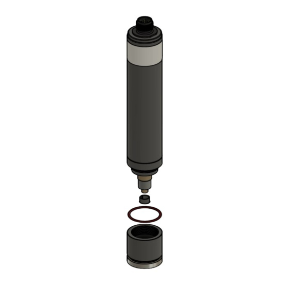
Information on this product Product overview Fig. 1: Product overview Electrical connection Sensor body Pressure compensation opening Working electrode O-ring 20 x 1.5 Membrane disc Protective cap Membrane cap G-holder 10 Electrode finger 11 Reference electrode 12 Tweezers TARAtec 9/10 9 / 44... -
Page 10: Name Plate
Information on this product Name plate A name plate is glued to each sensor, this shows the following information: Fig. 2: Example of a name plate Measured variables Sensor designation, sensor name Nominal measuring range of the sensor Permissible temperature range of the measuring water Maximum permissible pressure of the water being measured Signal transmission Power supply... -
Page 11: Safety
Restricted to the activities described in these operating instructions. Use only when in fault-free condition Use of original accessories and spare parts (see https://www.reiss- gmbh.com/english/datasheets.htm) Use other than for the intended purpose The sensor may not be used for measurements to demonstrate the absence of the disinfectant. -
Page 12: Personal Qualifications
Safety Personal qualifications The user must hold the following personal qualifications: He must have read and understood the operating instructions. He must have received training in the handling of the sensor. Rebuilding and modifications Opening the sensor and making modifications to it which can affect the safety and functionality of the sensor may be performed only by the manufacturer. - Page 13 Safety 3.5.3 Impacts, shocks and improper touching Impacts or shaking of the sensor, such as by dropping it, can damage it. Avoid impacts and shocks. Do not allow the sensor to be dropped. Do not touch the sensor electrodes at any time. Touching the reference electrode, or using emery paper on it, can damage it.
- Page 14 Safety 3.5.7 Loss of measured values when the sensor is removed After the sensor has been removed there is no longer a measured value, which can lead to incorrect dosing of the disinfectant. Switch off the measurement and control system or switch it over to ...
- Page 15 Safety 3.5.12 Incorrect chemical analytical methods Incorrect determination of the concentration of the disinfectant will lead to incorrect calibration of the sensor. Observe the recommended analysis methods as per the data sheet (see section 1.2, p. 5). Perform analytical work in accordance with the specifications in the manufacturer’s operating instructions for the analytical equipment.
-
Page 16: Commissioning
Commissioning Commissioning Installation requirements The following installation requirements must be satisfied: Continuous power supply and presence of water being measured Flow rate as specified on the data sheet Constant through flow rate There must be disinfectants present in the water being measured. ... - Page 17 Commissioning Put down the membrane cap on a clean surface. Fill the membrane cap with electrolyte to the brim. Fig. 4: Filling the membrane cap Place the G-holder on a clean surface with the fabric facing downwards. ...
- Page 18 Commissioning Carefully withdraw the tweezers from the membrane cap. The G-holder is now positioned in the membrane cap. Place the sensor body [1] upright on the membrane cap [2]. Rotate the sensor body anticlockwise until the thread is felt to engage.
-
Page 19: Insertion Into The Flow Chamber
Commissioning Insertion into the flow chamber The sensor must have been prepared for installation (see section 4.2, p. 16). Insert the sensor into a flow chamber of the type TARAflow FLC or any other suitable flow chamber. In order to insert the sensor correctly into the flow chamber: ... -
Page 20: Electrical Connection
Commissioning Electrical connection The sensor is inserted into the flow chamber (see section 4.3, p. 19). The following types of electrical connections to the sensor are available: 4.4.1 Connection with 0…+/-2000-mV signal output The sensor is provided with a 5-pin M12 screwed plug protected against polarity reversal. - Page 21 Commissioning 4.4.2 Connection with 4…20 mA signal output M12 screwed plug The sensor is provided with a 5-pin M12 screwed plug protected against polarity reversal. The connection pins are assigned as follows: Fig. 10: Connection pin assignment (5-pin) (not assigned) (not assigned) (not assigned) Connection with a 2-pole screwed terminal block...
-
Page 22: Initial Calibration
Commissioning 4.4.3 Connection with Modbus signal transmission The sensor is provided with a 5-pin M12 screwed plug protected against polarity reversal. There are no termination resistors within the sensor. The connection pins are assigned as follows: Fig. 11: Connection pin assignment (5-pin) (not assigned) +9…+30 V RS485 B... -
Page 23: Calibration
Calibration Calibration The sensor outputs a signal proportional to the concentration of the disinfectant in the water being measured. In order to assign the value of the sensor signal to the concentration of the disinfectant in the water being measured, the sensor must be calibrated. ... - Page 24 Calibration Measured variables Recommended analytical methods Hydrogen peroxide Single-stage sulphuric acid titration with potassium permanganate (for the procedure see appendix) Peracetic acid Two-stage sulphuric acid titration with potassium permanganate and sodium thiosulphate (for the procedure see appendix) Chlorine DPD-1 Up to 10 ppm: Photometer for chlorine Iodometry Up to 200 ppm:...
-
Page 25: Removal
Removal Removal Removal of the sensor can lead to an incorrect measured value at the input to the measuring and control device, which can cause the control circuit to apply uncontrolled dosing. Before removing the sensor: Switch off the measurement and control system or switch it over to manual operation. -
Page 26: Changing The Electrolyte And Membrane Cap
Maintenance Changing the electrolyte and membrane cap Unscrew the membrane cap. Using tweezers, remove the G-holder from the membrane cap. Empty the electrolyte out of the membrane cap. Rinse the membrane cap with mains water. Rinse the electrode finger with mains water. - Page 27 Maintenance Lay a piece of special emery paper on a clean, smooth surface. Hold the sensor upright. Hold the special emery paper in place and move the tip of the working electrode over it at least twice. Use a fresh area of the emery paper for each pass.
-
Page 28: Troubleshooting
Troubleshooting Troubleshooting Various factors in the environment can affect the sensor. If irregularities occur, it may be useful to check these factors: Flow rate Measuring cable Measuring and control device Calibration Dosing equipment Concentration of the disinfectant in the dosing container ... -
Page 29: Fault Overview
Troubleshooting Fault overview Fault Cause Corrective action Sensor cannot Run-in time too short. Wait until the run-in be calibrated / time has elapsed (see the measured section 4.5, p. 22). value deviates Repeat the calibration from the after a few hours. analytical Membrane torn. - Page 30 Troubleshooting Fault Cause Corrective action Unsuitable titration Repeat the titration method using a suitable method (see appendix, p. 41). Deposits on the Change the membrane membrane cap (see section 7.2, p. 26). Air pockets between the Unscrew the G-holder/membrane/ membrane cap.
- Page 31 Troubleshooting Fault Cause Corrective action Lack of galvanic Create galvanic isolation isolation. Return the sensor to the supplier for checking / reconditioning. The sensor is defective. Return the sensor to the supplier for checking / reconditioning. Unstable Membrane torn.
- Page 32 Troubleshooting Fault Cause Corrective action Lack of galvanic Create galvanic isolation isolation. Return the sensor to the supplier for checking / reconditioning. The reference electrode Return the sensor to is exhausted and/or the supplier for contaminated. checking / reconditioning.
- Page 33 Troubleshooting Fault Cause Corrective action Lack of galvanic Create galvanic isolation isolation. Return the sensor to the supplier for checking / reconditioning. The sensor is defective. Return the sensor to the supplier for checking / reconditioning. Underdriving Run-in time too short.
- Page 34 Troubleshooting Fault Cause Corrective action The sensor is defective. Return the sensor to the supplier for checking / reconditioning. The sensor is connected No signal Connect the sensor to the measuring and correctly to the control device with the measuring and control wrong polarity.
- Page 35 Troubleshooting Electronics Signal Underdriving Overdriving transmission Digital Modbus RTU <0 ppm/ % Measured value > Measurement range <0 mA >+2000 mV 0 … +2000 mV Orange LED Orange LED lights up flashes regularly <-2000 mV 0 … -2000 mV Orange LED Orange LED ...
-
Page 36: Special Checks
Troubleshooting Special checks 8.2.1 Tightness of the membrane cap Unscrew the membrane cap from the sensor (see section 7, p. 25). Dry the outside of the membrane cap. Prepare the membrane cap (see section 4.2, p. 16). ... - Page 37 Troubleshooting 8.2.3 Checking the zero point The electronics must have been tested and found to be OK. Prepare the sensor (see section 4.2, p. 16). Connect the sensor to the measuring and control device. Fill a glass beaker with mains water (without any disinfectant!). ...
- Page 38 Troubleshooting 8.2.4 Signal The zero point checking must have been performed successfully. Add the relevant disinfectant to the mains water in the glass beaker (see section 8.2.3, p. 37). Stir the sensor steadily round in the glass beaker for five minutes. ...
-
Page 39: Technical Data
Technical data Technical data Information on the technical data can be found at the following Internet address: https://www.reiss-gmbh.com/english/datasheets.htm Deinstallation and storage To deinstall a sensor and prepare it for storage, proceed as follows: Unscrew the membrane cap. Using tweezers, remove the G-holder from the membrane cap. -
Page 40: Warranty
Each return shipment must be accompanied by a completed declaration of clearance. This can be found at the following Internet address: https://www.reiss-gmbh.com/forms/?lang=en. In case of contamination or missing or not completed declaration of clearance, a cleaning fee will be charged. -
Page 41: Appendix
Appendix Appendix Recommended titration procedure For the determination of hydrogen peroxide (H ), only the 1st titration stage need to be performed. For the determination of peracetic acid (PAA) the 1st and 2nd titration stages need to be performed. Procedure: The titration must be performed quickly. - Page 42 Appendix 14 Appendix Peracetic acid Peracetic acid Peracetic acid Concentration 0…200 >200…2000 >2000…20000 (2%) range in ppm 25 ml sample of the water being 25 ml sample of the water being 5 ml sample of the water being Material measured measured...
- Page 43 Appendix 14 Appendix Peracetic acid Peracetic acid Peracetic acid Stirring continuously, titrate with thiosulphate until the sample turns colourless. Make a note of the consumption (B) of thiosulphate in ml. Calculation of A * 6.8 A * 68 A * 340 the H = concentration in ppm H...
- Page 44 Reiss GmbH Eisleber Str. 5 D - 69469 Weinheim Germany...
Need help?
Do you have a question about the TARAtec P9 and is the answer not in the manual?
Questions and answers