
Summary of Contents for EDAC 320
- Page 1 EDAC 320 User Manual Page 1 of 69 EDAC Electronics Ltd EDAC 320 User Manual Document Version 1.0 For Version 5 Hardware and Above For Firmware from 1.0 www.edacelectronics.com © 2005 EDAC Electronics Ltd...
-
Page 2: Table Of Contents
7.1.1 Edit Connections............................. 42 7.1.2 Modem ..............................43 Downloading Log Files........................44 Downloading/Uploading Contacts List ..................... 44 EDAC 320 – Notification, Control and Queries ..............46 Alarm Notification Messages ......................46 Controlling Outputs .......................... 46 8.2.1 Switching Commands ..........................46 8.2.2 Responses .............................. - Page 3 10.4 Power Supply Monitoring ......................... 60 10.4.1 Hardware Setup ............................60 10.4.2 Configuration Setup ..........................61 10.5 RS232 AT Commands ........................62 11. Glossary ..........................65 12. Product Support.........................67 13. Notes...........................68 14. Document History ......................69 www.edacelectronics.com © 2005 EDAC Electronics Ltd...
-
Page 4: Overview
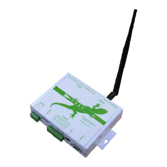
The EDAC 320 is a cost effective, cellular based remote monitoring control and logging system. Based off the tried and true EDAC SMS 300 series product the EDAC 320 integrates all of the features of the SMS 300 as well as adding some new ones. - Page 5 Modem Through-mode The internal GSM modem can be used in through mode to provide a wireless serial link to an external device (e.g. PLC) or the EDAC 320 SMS Command Mode The EDAC 320 can forward messages received via the serial port www.edacelectronics.com...
-
Page 6: Getting Started
SIM cards. The SIM must be fitted into the unit before the EDAC 320 will operate. To do this the unit must be powered down and end plate must be removed to expose the SIM connector. Remove the connector blocks from the end plate (the end the aerial connects to) and remove the screws securing the end plate as detailed in Fig 3.1a. - Page 7 Insert the SIM into the holder as shown below in Fig 3.1d. Due to the shape of the SIM card itself it should not be possible to insert the card in an incorrect manner. www.edacelectronics.com © 2005 EDAC Electronics Ltd...
-
Page 8: Circuit Switched Data Number
The unit should now be ready for use. 3.1.1 Circuit Switched Data Number Some features of the EDAC 320 require a ‘Circuit Switched Data’ (or CSD) number to be enabled on the SIM to function correctly. Having a data number enabled means that the SIM card will have two different phone numbers associated with it, one for voice/SMS and another for CSD communications. -
Page 9: Gprs
320’s functionality. 3.2.1 Power The power LED indicates if the EDAC 320 is powered up, and if it is the status of the SD/MMC data card. Powered up, data card inserted and accessible... -
Page 10: Hardware Installation
4. Hardware Installation 4.1 Power Supply The EDAC 320 has a universal input power supply. The unit can accept AC or DC input power between 12 and 28 volts. The EDAC 320’s idle current draw is quite low, however because of the nature of cellular radio communications, peak current draw can be quite high, the average current draw also varies depending on the input voltage. -
Page 11: Dc Power Input
AC power supply you intend to use, contact your supplier for more information. It is required for warranty purposes that external fusing is fitted to the EDAC 320 when powered from AC supplies. This prevents damage from ground loops and surges. Below Fig 4.1.3 details how the external fusing should be connected. -
Page 12: Inputs
4.2 Inputs The EDAC 320 has eight fully configurable inputs, capable of accepting three different types of input signals, Digital (N.O. or N.C.), 4-20mA analog and 0-5V analog. The following sections detail common configurations for these types of inputs. 4.2.1 Jumper configuration The unit has a series of ‘hardware jumpers’... -
Page 13: Digital Input Configuration
4.2.2 Digital Input Configuration The EDAC 320 requires a ‘clean contact, voltage free’ digital input. Basically what this means is that the input needs to be shorted to ground (for N.O.), or disconnected from ground (for N.C.) to indicate an alarm condition. -
Page 14: 4-20Ma Analog Input Configuration
0VDC. The microprocessor in the EDAC 320 constantly monitors the voltage on the inputs checking if the input is shorted to ground or not. No external voltage should be presented to the input terminals of the EDAC 320 when configured as digital. -
Page 15: 0-5V Analog Input Configuration
0-5V sensors are probably the least commonly used of the three types or sensors. This is due to the fact that part of the signal voltage can be lost across long cable runs. A typical wiring schematic is shown in Fig 4.2.4. www.edacelectronics.com © 2005 EDAC Electronics Ltd... -
Page 16: Outputs
4.3 Outputs The outputs on the EDAC 320 are of a relay type, meaning that they can switch small to medium voltages and currents (Below 50V and 2A AC or DC). Where higher power is required the relays can be used to drive larger relays. -
Page 17: Relay Switching
Note that the load can be powered from the same power supply as the EDAC 320, however the supply will need to match the voltage requirements of the load and will need to be able to supply enough current to power both the EDAC 320 and the load. -
Page 18: Mounting
4.5 Other 4.5.1 RS232 The EDAC 320 has one RS-232 (serial) port which is used primarily for configuration of the unit using the ‘EDAC 320 Configuration Manager’ software (see section 6 for more information on using ‘320 Configuration Manager’. -
Page 19: Software Installation
5. Software Installation The following section details the process to install the ‘EDAC 320 Configuration Manager’ and ‘EDAC 320 Remote Management’ software which is used to setup, configure and remotely manage the EDAC 320. Also detailed is the process for correctly installing the EDAC 320 USB drivers. -
Page 20: Edac 320 Remote Management
Click on the ‘Finish’ button and the application will launch. 5.2 EDAC 320 Remote Management To begin the installation process for the ‘EDAC 320 Remote Management’ software, execute the ‘EDAC 320 Remote Management Installer.exe’ file in the ‘Remote Management’ Folder, located on the CD-ROM supplied with the product. - Page 21 Click ‘Next’ to proceed and the software will be installed. The following window will appear when installation is complete. Fig 5.1d Software Installation – Finish Click on the ‘Finish’ button and the installation will be complete. www.edacelectronics.com © 2005 EDAC Electronics Ltd...
-
Page 22: Usb Drivers
Ensure the EDAC 320 CD-ROM included with the product is inserted into the CD-ROM drive before proceeding. Connect the EDAC 320 to a free USB port on the PC using a USB-A to USB-B cable. The PC should detect that the USB cable has been connected and show display the windows shown in Fig 5.3.1a to begin the installation... - Page 23 In this window ensure only the ‘Specify a Location’ box is ticked, click on the ‘Browse’ button and locate the ‘Win 98 and ME’ folder on the EDAC 320 CD-ROM. Click on the ‘Next’ button to continue., the window in Fig 5.3.1d will appear.
- Page 24 COM port). With the EDAC 320 connected to the PC via the USB cable, open the ‘Control Panel’ of the PC Double click on the ‘System’ icon. From the window that appears (shown in Fig 5.3.1f) click on the ‘Device Manager’ tab.
- Page 25 Configuration Manager’. Note that the port number assigned to the EDAC 320 USB interface can be changed if required. To change the port number, right click on the ‘USB Serial Port’ heading and select ‘Properties’. This will open the window shown in Fig 5.31h...
-
Page 26: Windows © 2000/Xp/Server 2003 And Windows © Xp/Server 2003 64Bit Edition
Ensure the EDAC 320 CD-ROM included with the product is inserted into the CD-ROM drive before proceeding. Connect the EDAC 320 to a free USB port on the PC using a USB-A to USB-B cable. The PC should detect that the USB cable has been connected and show display the windows shown in Fig 5.3.2a to begin the installation... - Page 27 ‘Include this location in the search’ tick box as shown above. Click on the ‘Browse’ button and find the location of the most suited driver folder on the EDAC 320 CD-ROM Click on ‘Next’ to proceed. The window shown in Fig 5.3.2d will then appear.
- Page 28 COM port). With the EDAC 320 connected to the PC via the USB cable, open the ‘Control Panel’ of the PC Double click on the ‘System’ icon. From the window that appears (shown in Fig 5.3.2f) click on the ‘Hardware’ tab, and then click on the ‘Device Manager’...
- Page 29 Fig 5.3.2h Device Manager - COM Ports Note that the port number assigned to the EDAC 320 USB interface can be changed if required. To change the port number, right click on the ‘USB Serial Port’ heading and select ‘Properties’. This will open the window shown in Fig 5.3.2i...
- Page 30 Click ‘O.K.’ on all properties pages to close and save settings. The system should be restarted after the port number has been changed to ensure the settings are applied properly. www.edacelectronics.com © 2005 EDAC Electronics Ltd...
-
Page 31: Edac 320 Configuration Manager
The ‘320 Configuration Manager’ software has the ability to upload and download configurations to and from the EDAC 320 via a serial or USB connection to the unit. It can also load and save configuration to a file on the PC as well as displaying real time diagnostics information about the EDAC 320 unit connected to the PC. -
Page 32: Unit Page
6.3 Unit Page The diagram in Fig 6.3 below shows the ‘Unit Page’ of the ‘EDAC 320 Configuration Manager’ software. This page can be accessed from any screen of the software by clicking on the ‘Unit’ branch of the tree on the left hand side of the screen (as circled in red). -
Page 33: General' Tab
‘Unit’ page of the software. • Site Name The ‘Site Name’ is the text which is included at the beginning of every outgoing message from the EDAC 320. This normally identifies the location or the owner of the unit. - Page 34 Note that the ‘EDAC 320 Configuration Manager’ software comes included with two files containing the default GPRS settings, one for Vodafone NZ, the other for Telstra Aust GSM. It is recommended that new configurations are started from these default files. Use the ‘Open’ feature (see section 6.2) of the software to open either of...
-
Page 35: Email' Tab
This field contains the email address that will be used as the ‘From Address’ in all outgoing emails from the EDAC 320. Note that this does not necessarily need to be an active email address if one is not able to be dedicated to the unit, however any email sent from the unit the is bounced or undeliverable will cause an error report be sent back to this address. -
Page 36: Logging' Tab
Fig 6.3.4 ‘Logging’ Tab • Enable Data Logging Ticking this box enables the data logging features of the EDAC 320. This box must be selected for any of the following settings/options to become active. • Update LOG.CSV on the MMC card every <time> seconds This option sets the global logging rate for all inputs. -
Page 37: Inputs
The ‘Input’ pages configure the input options for the EDAC 320 and can be accessed by clicking the appropriate tree branch fro the input that is to be configured on the left hand side of the ‘EDAC 320 Configuration Manager’... -
Page 38: Alarm A' Tab
6.4.2 ‘Alarm A’ Tab The ‘Alarm A’ tab configures the alarm settings and notifications messages for each input on the EDAC 320. This page can be accessed by clicking on the ‘Alarm A’ tab from the input tree branch. -
Page 39: Alarm B' Tab
The EDAC 320 monitors and records the current state of all configured inputs. If this option is selected on power up the EDAC 320 unit will compare the current state of the input with the last know state, and will send the appropriate message if it has changed. If this option is not selected the EDAC 320 will send notification messages for all alarm conditions on power-up. -
Page 40: Outputs
This is the message which is sent to the contacts when the output is turned off. (40 char max) • Contacts Select the appropriate boxes for the contacts that are to receive ‘On’ and ‘Off’ messages www.edacelectronics.com © 2005 EDAC Electronics Ltd... -
Page 41: Diagnostics Interface
• GPRS Connection This indicates the state of the EDAC 320’s GPRS connection. If the GPRS connection fails, then a button will appear that will allow the user to force the unit to try to re-connect to the network. -
Page 42: Edac 320 Remote Management
The ‘EDAC 320 Remote Management’ software requires configuration before it can be used to remotely access log files and contact lists on a 320. The software also needs to be associated with a modem on the PC where it is installed. The software can also be setup to connect to several different EDAC 320 units. -
Page 43: Modem
7.1.2 Modem The second step is to configure the modem that the ‘EDAC 320 Remote Management’ software will connect through. A dial up modem MUST be fully installed on the PC and connected to a working phone line for any of the features of this software to function. -
Page 44: Downloading Log Files
It is highly recommended that the contact list is downloaded into the software before it is edited and uploaded back into the unit as the contact list displayed in the software will completely overwrite the list saved in the EDAC 320. - Page 45 Fig 7.3 Uploaded Contacts The contacts can now be altered as required, ensure all changes are correct before uploading them back into the remote EDAC 320 unit. www.edacelectronics.com © 2005 EDAC Electronics Ltd...
-
Page 46: Edac 320 - Notification, Control And Queries
8.2 Controlling Outputs The user can remotely control the state of any output by sending an SMS message to the unit. The EDAC 320 uses two levels of security to ensure only authorised users can switch outputs. These are ‘PIN’ security and ‘Caller ID’... -
Page 47: Multiple Output Commands
If an output command has been sent by a valid user (i.e. phone number programmed in contact list) and the command is valid but the output is not enabled, the EDAC 320 unit will respond with the following message. EDAC 320 Demo Output ‘x’... -
Page 48: Advanced Sms Commands
(see section 5.6 for more information on configuring output responses). 8.4.3 SMS Forwarding to RS232 port The EDAC 320 can forward SMS received messages out through the RS-232 port. This can allow the user to control various other pieces of equipment that can respond to RS-232 serial commands. -
Page 49: Updating Contacts List Via Sms
Fig 8.4.3 Supported SMS Forwarding Characters 8.4.4 Updating Contacts List via SMS Cellphone numbers in the contacts list in the EDAC 320 can be updated via SMS. This feature is useful if a user changes service providers or changes cellphone numbers Note that email addresses in the contacts list cannot be updated via SMS. -
Page 50: Email Commands
Note that the email address that the command is sent from will ether need to be in the contacts list of the EDAC 320 or ‘Public Queries’ will need to be enabled for the unit to reply to some commands (see section 6.3.1... -
Page 51: Data Logging
9.2 SD Data Card The EDAC 320 uses a data flash card to store data logged form the 320’s inputs and outputs. This data can be retrieved from the SD card, and analysed at any time. This section will cover the initialisation and installation of the data card in the EDAC 320. -
Page 52: Installing/Removing Sd Cards
The SD card is now ready to be inserted and used with the EDAC 320. 9.2.3 Installing/Removing SD cards Once the SD/MMC card has been initialised and formatted it can then be inserted into the EDAC 320 for use. Follow the instructions below to insert the SD/MMC card into the EDAC 320. - Page 53 Fig 9.2.3a Locking Data Card into Place Push the card in until it locks in place, the card may protrude slightly from the side of the EDAC 320 a shown below in Fig 9.2.3b, or it may sit flush with the endplate depending on the type of data card in use.
-
Page 54: Log File Formats
All this information combined in the table gives fully time date stamped entries for each logged input. www.edacelectronics.com © 2005 EDAC Electronics Ltd... -
Page 55: Alarm.log
(such as digital cameras, MP3 players, iPods, USB flash disks etc) from the PC before proceeding. Remove the data card from the EDAC 320 and insert into the card reader, the system should recognise the new volume. From ‘My Computer’ find and double click on the ‘Removable Disk’ entry as shown below. -
Page 56: Remotely
A new file will be created when the data card is inserted back into the EDAC 320. 9.4.2 Remotely section 7 for a full explanation of the process for setting up the ‘EDAC 320 Remote Management’ software and downloading log files from an EDAC 320 unit. www.edacelectronics.com © 2005 EDAC Electronics Ltd... -
Page 57: Application Notes / Advanced Features
Some basic commands should be entered into the PC modem to set it up to work with the EDAC 320. Below is an example of the commands that need to be entered to set up the PC modem and initiate the connection. - Page 58 Fig. 10.2a Output Config The input that is to control the output then needs to be set up. Bring up the appropriate input configuration page as shown below in Fig 10.2b. www.edacelectronics.com © 2005 EDAC Electronics Ltd...
-
Page 59: Automatic Remote Output Switching
An example application for this feature could comprise of a frost monitoring and irrigation start system. One EDAC 320 may be connected to a temperature sensor out in the middle of the orchard, but the pump that needs to be started when a frost occurs is some distance away at the edge of the orchard. -
Page 60: Power Supply Monitoring
10.4 Power Supply Monitoring The EDAC 320 has the ability to monitor the voltage supplied to it when running from a D.C. power supply. Input 8 is dedicated to PSU monitoring when this function is enabled. This feature can be particularly useful in solar powered applications as the 320 can monitor the status of the system batteries. -
Page 61: Configuration Setup
Alarm conditions and notification messages can now be set up for the power supply monitoring. Change to the ‘Alarm A’ tab to configure these. Fig. 10.4.2a shows how these might be typically set up. Fig 10.4.2a PSU Monitoring Alarms www.edacelectronics.com © 2005 EDAC Electronics Ltd... -
Page 62: Rs232 At Commands
It should be noted that using these commands is recommended for advanced users only. Incorrect use of these commands may render the unit inoperable. To use one of the commands type the command into the terminal window and press enter. The EDAC 320 will respond as required. - Page 63 Sets the EDAC 320 configuration back to factory defaults. This command will clear all settings, messages and contacts. AT&R Forces the EDAC 320 to perform a soft reset. Until will restart and initialise as if it has been re-powered. This command does not affect configuration...
- Page 64 ‘Through Mode Data Connection’ (see section 10.1 for more information). ### takes the EDAC 320 out of a transparent serial link, and enters ‘Command Mode’, allowing access commands as if connected directly to the RS-232 port.
-
Page 65: Glossary
11. Glossary SMS (or Short Message Service) is a text message delivery service on cellular networks. The EDAC 320 uses SMS messaging as it primary means of communication A SIM card (or Subscriber Identity Module) is a small card used on GSM cellphone network. The SIM card contains information about the account that the phone is connected on, as well as the number of the phone. - Page 66 320 to be configured form PCs that do not have a RS-232 interface. SD (or Secure Digital) is a type of flash data card used by the EDAC 320 to store log files. SD cards are commonly found in digital cameras and MP3 players. Information on an SD card can be accessed by inserting the card into a PC with a card reader installed.
-
Page 67: Product Support
12. Product Support For end-user level customer support, contact your local distributor or installer. www.edacelectronics.com © 2005 EDAC Electronics Ltd... -
Page 68: Notes
13. Notes www.edacelectronics.com © 2005 EDAC Electronics Ltd... -
Page 69: Document History
14. Document History Version Date Author Notes 20/07/2006 Chris Butler Document Creation 06/09/2006 Chris Butler Final Draft Released www.edacelectronics.com © 2005 EDAC Electronics Ltd...
Need help?
Do you have a question about the 320 and is the answer not in the manual?
Questions and answers