
Summary of Contents for Ronan X96S
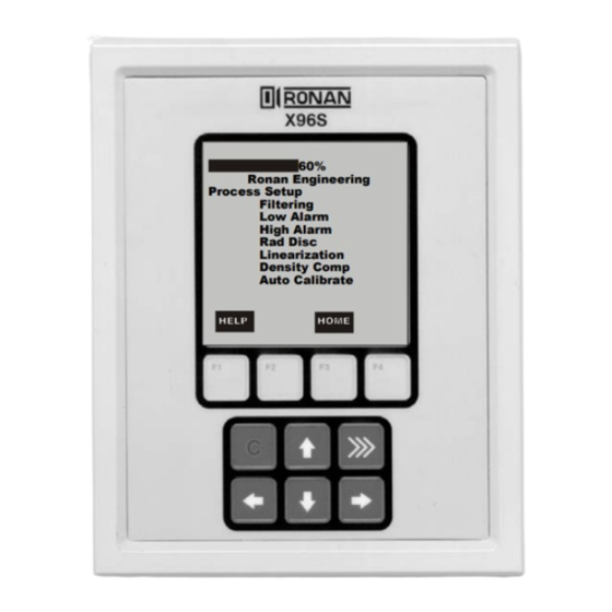
- Page 1 Instructions Operating Manual X96S Level with Density Compensation Gage Ronan Engineering Process Setup Filtering Low Alarm High Alarm Rad Disc Linearization Density Comp Auto Calibrate...
-
Page 2: Table Of Contents
Table of Contents OVERVIEW......................... 3 Advantages..............3 Gamma's Advantages..............................3 X96S Advantages................................3 BASIC CONCEPTS ......................4 Communications..............4 4-20 MA..................................4 HART..................................... 4 Variables..............4 Communication Variables.............................. 4 Device Variables ................................5 Configuration Variables..............................5 THEORY ..........................6 Theory of Radiation Gaging............ 6 Principles of Operation............ - Page 3 ION Chamber..............42 ELECTRONICS ........................ 47 X96-2001PL..............47 X96-2002PL..............47 X96-2003PL..............47 X96-2004PL..............47 X96-2007PL..............47 X96-2008PL..............48 X96-2009PL..............48 OPTIONS.......................... 49 X96S Mechanical Chassis Part Numbers......... 49 X96S Electronic Module Part Numbers.......... 49 REGULATIONS ........................ 50 DRAWINGS ........................51...
-
Page 4: Overview
Overview The X96S is a family of measurement products that is intended to replace the current X96N and X99 product families. These products: • use nuclear measurement techniques, • support all features of the current X96N and X99 products, •... -
Page 5: Basic Concepts
Basic Concepts Communications The Ronan X96S Level gage provides both 4-20 mA current loop and HART communications. 4-20 MA For many years, the field communication standard for process automation equipment has been a 4-20 mA current loop signal. The current varies in proportion to the process variable being represented. In typical applications, a signal of 4mA will correspond to the lower limit (0%) of the calibrated range and 20mA will correspond to the upper limit (100%) of the calibrated range. -
Page 6: Device Variables
Value Level Level Density Density Uncomp.Level Uncompensated Level Density Comp Density Compensation Head Temp Head Temperature Not Assigned Not Assigned Configuration Variables The Ronan X96S Level with Density Compensation gage has many configuration variables that are accessed through its menus. -
Page 7: Theory
HIGH output of counts. When the process level is high the process material "shields" the detector and prevents radiation from reaching the detector, producing a LOW output of counts. The X96S Microprocessor converts the detector signal to user's measurement units of level: m, mm, cm, in, ft. -
Page 8: Principles Of Operation
The Calibration (or Referencing) procedure relates detector output (in counts) to numeric values that accurately represent the actual process level. The level algorithm used by the X96S software is a simple transfer function. That is, the relationship between the detector output and the process level is mathematically expressed as: ... -
Page 9: Password
Password Notice: To access the Programming Menu, the Password is 101010. Step 1: Power Up – You should now be on the Status Screen. Step 2: Press F3 to go back. Step 3: Now enter the password. (All digits are set at 000000 at this point.) Press to get the digit to be # one Press... -
Page 10: Menus/Operation
_____________________________ Menus/Operation The Ronan X96S Level with Density Compensation Gage uses a tree structured menu system. Ronan X96S–Level,Den Comp Variables Variables Variable Mapping Status Displays Configuration Variable Mapping PV is [var mapped to PV] Digital Outputs Level [value units] SV is [var mapped to SV] Digital Inputs Uncomp.Level[value units]... - Page 11 Configuration Level Filter Operation Operation Type RC, Ist order Level Config Dyn Track [enable] Density Config Level Filter Sigma [number] Comp.Ratio Dens.Filter Fast TC [seconds] Head Temp Config Rad.Disc Config Fast Counter [number] Alarms Dens.Comp Config Medium TC [seconds] Hardware Detector Fault Slow Counter [number] Hart...
- Page 12 Next Wipe Test (Date) Next Shutter Test (Date) Analog Out Config Loop 1 (PV) Loop 2 (SV) Loop 3 (TV) Pwr Src (Internal/External) Loop () ()V X96S-2005 X96S-2004, chan 1 X96S-2004, chan 2 None HART output None X96S-2005 CONFIGURATION MENU Ser.port 1...
- Page 13 Configuration Detectors Hardware Operation Card 2 Func Level Config System Hardware Card 3 Func Density Config Source Type Card 4 Func Comp.Ratio Analog Out Config Card 5 Func Head Temp Config HART output Ser.po Card 6 Func Alarms Detectors Card 7 Func Hardware Card 8 Func Hart...
- Page 14 Digital Outputs Output Output Relay 1 Select Sources Relay 2 Polarity Relay 3 Relay 4 TTL 1 TTL 2 TTL 3 TTL 4 Select Sources Alarm 1 [yes/no] Alarm 2 [yes/no] Alarm 3 [yes/no] Alarm 4 [yes/no] Alarm 5 [yes/no] Alarm 6 [yes/no] Alarm 7 [yes/no] Alarm 8 [yes/no]...
- Page 15 Auto Cal Setup Auto Cal [number] Auto Cal Auto Cal 1 Auto Cal [state] Auto Cal Setup Auto Cal 2 [Disable, Enable, Suspend] Auto Cal Status Auto Cal 3 Type Manual AC Filter [seconds] Auto Cal 4 [sensor rise, sensor fall, both] G.
- Page 16 Diagnostic Level Level Raw Counts Density Filter Counts Rad. Disc Ref Date Alarms Ref Level Cal Level Ref Cap Cal Cap Dens.Comp.Capt Density Raw Dens Cnts Filter Cnts Ref Cap Cal Cap Ref Density [SGU] Calibr Density [SGU] 1/uT Rad. Disc. Rad Disc Cnts Filt.
-
Page 17: Variables Menu
The root menu is titled “Ronan X96S – Level”. It contains the following items: ITEM FUNCTION Variables Selecting this choice takes the user to the Variables menu Status Display Selecting this choice takes the user to the Displays menu Configuration... -
Page 18: Status Display Menu
Status Display Menu The Status Display menu is used to configure the device status display. It contains the following items ITEM FUNCTION Analog Bar Shows the current state of the analog bar display (enabled or disabled) and allows the user change the state. Line 1: Shows the data to be displayed on line 1 of the status display and allows the user to change the selection... -
Page 19: Configuration Menu
Configuration Menu The Variables menu is used to access area configuration menus. It contains the following items: ITEM FUNCTION Operation Selecting this choice takes the user to the Operation menu Level Config Selecting this choice takes the user to the Level Config menu Density Config Selecting this choice takes the user to the Density Config menu Comp.Ratio... -
Page 20: Level Filter Menu
Monitor MEANING ERROR Filter is not initialized (this state should not occur during normal operation of the X96S Weigh Scale) FILL The slow filter buffer is filling. TRACK The (slow or medium or fast filter buffer is filled and the filter is tracking changes in... -
Page 21: Density Filter Menu
Monitor MEANING ERROR Filter is not initialized (this state should not occur during normal operation of the X96S Weigh Scale) FILL The slow filter buffer is filling. TRACK The (slow or medium or fast filter buffer is filled and the filter is tracking changes in... -
Page 22: Rad.disc Config Menu
Rad.Disc Config Menu Radiation Discrimination is used where radiography is frequently used to inspect vessel welds. There are two types of configurations. The first is using an optional external detector to sense the changes in the background radiation. This configuration provides the maximum type of protection because it senses small changes in background. -
Page 23: Dens.comp Config
Linearization Menu The X96S is capable of performing a multi-point linearization of the level data when required by an application. The linearization table contains thirty-two entries, numbered 1 through 32. Each entry consists of a measured value, an actual value, and a flag that indicates if the entry is used The Linearization menu is used to control the linearization mechanism. -
Page 24: Config Linearize Menu
Measured Shows, and allows the user to set, the measured value associated with this linearization table entry. This is a value calculated by the X96S. Actual Shows, and allows the user to set, the actual value associated with this linearization table entry. -
Page 25: Comp.ratio Menu
Units is one of the following: Density Units MEANING specific gravity degTwad degrees twaddle degBrix degrees brix degBaum_hv degrees baume heavy degBaum_lt degrees baume light degAPI degrees API Percent_sol_wt percent solids by weight degBall degrees balling percent_StmQual percent steam quality Comp.Ratio Menu The Comp.Ratio menu is used to configure the parameters associated with the density compensation. -
Page 26: Hardware Menu
Source MEANING Head Temp Uses the Head Temperature of the detector for the source of the alarm Filtered Counts Uses the Filtered Counts from the detector for the source of the alarm The Alarm on 4-20 mA output has one of the following options: Option Meaning None... -
Page 27: Source Type Menu
Shows and allows the user to set TV to a specific output (X96S-2005, X96S-2004, Chan1 or Chan 2, None) Pwr Src Shows and allows the user to set where the source of power is internal (X96S) or external. Hart Output Menu... -
Page 28: Hart Menu
Shows the HART universal command revision to which this device is conformant Spec Rev Shows the HART specification revision to which this device is conformant System Menu The System menu is used to provide information about the X96S. It contains the following items: ITEM FUNCTION Serial #... -
Page 29: Digital Outputs Menu
Selecting this item takes the user to the TTL 4 menu Relay Menus The Relay menus (Relay 1 through Relay 4) are used to configure the X96S relay outputs. These four relay menus show the settings of the corresponding relay output and allow the characteristics of the output to be changed. -
Page 30: Ttl Menus
Normally closed TTL Menus The TTL menus (TTL 1 through TTL 4) are used to configure the X96S TTL outputs. These four TTL menus show the settings of the corresponding TTL output and allow the characteristics of the output to be changed. -
Page 31: Digital Inputs Menu
Polarity is one of the following: Polarity MEANING Not Driven Normally not driven Driven Normally driven Digital Inputs Menu This menu is used to view and configure the digital inputs. It contains the following item: ITEM FUNCTION Input 1 Selecting this item takes the user to the Input 1 menu Input 2 Selecting this item takes the user to the Input 2 menu Input 3... -
Page 32: Auto Cal Menu
Auto Cal Menu This menu is used to view and setup the Auto Calibration for the X96S Level with Density Compensation Gage. It contains the following items: ITEM FUNCTION Auto Cal Setup Selecting this item takes the user to the Auto Cal Setup menu Auto Cal Status Selecting this item takes the user to the Auto Cal Status menu. -
Page 33: Auto Cal Configuration Menu
State Show the state of the auto cal. Level Show the user at what level the X96S will be auto calibrated Trigg.Delay Shows and allow the user to change the Trigg.Delay time. The Trigg.Delay is the amount of time the auto-cal detector must be tripped before an auto calibrations can begin. -
Page 34: Calibration Menu
Aux Loop Cfg Selecting this item takes the user to the Aux Loop Cfg menu Calibrate Level Menu This menu is used to view and control the calibration of the X96S Level portion of the Gage. It contains the following items: ITEM... - Page 35 Low Ref Level is one of the following State MEANING Reference This item invokes a method that performs the low reference procedure. After the reference procedure is completed, it is important the user access the Ref Lev value and insert or acknowledge the value. Ref Level Shows and allows the user to set the reference to the level of the process Ref Cap...
-
Page 36: Calibrate Dens Menu
Calibrate Dens Menu This menu is used to view and control the calibration of the X96S Density portion of the Gage. It contains the following items: ITEM FUNCTION State Shows the state of the level configuration process Low Ref Dens... -
Page 37: Loop Config Menu
Cal Level Shows the user at what level the X96S was calibrated Ref Cap Shows the user at what (level) detectors counts the X96S was referenced Cal Cap Shows the user at what (level) detector counts the X96S was calibrated... -
Page 38: Density
ITEM FUNCTION Comp.Ratio Capt Shows the user at what (density compensation) detector counts the X96S was calibrated or referenced depending on if the density compensation is low phase or high phase Density ITEM FUNCTION Raw Dens Cnts Shows the user the Raw Counts (unfiltered counts) which is from the Density detector Filt.Counts... -
Page 39: Alarms
Alarms ITEM FUNCTION Sys.Alarm Shows the status of the System Alarm. 0 = Reset. Any other value indicates the system alarm is trip. The value indicates which card is the source. Det.Fault Shows the status of the System Alarm. 0 = Reset. Any other value indicates the system alarm is trip. -
Page 40: Configuration
After installation at your site, you may need to reconfigure the system to fit your application. The goal is to correlate the X96S output with your actual level readings. The list below summarizes the activities that are detailed in the remainder of this chapter: - Check the factory-default settings to be sure they are appropriate for your circumstances. -
Page 41: Detector
Detector Scintillator Detector Description The Ronan scintillation detector consists of three main components: The plastic scintillation crystal, the photomultiplier tube (PMT), and the associated electronics. Scintillation Crystal The crystal used for the Weigh System is poly vinyl toluene (PVT) plastic. The crystal produces light pulses which are proportional to the incident radiation events striking it. - Page 42 Therefore, the scintillation detector IS NOT field serviceable. Should a problem arise with the detector, the entire Detector Assembly should be returned to Ronan for repair/replacement.
-
Page 43: Ion Chamber
(R2) on the X96S input board. (B-9742-K). The detector’s gain is adjusted whenever the signal output of the detector is too high and may saturate the input of the X96S, which is approximately 3.5VDC. The output must be less than 3.0VDC with an empty vessel. - Page 44 The most important components of the amplifier are the operational amplifier (IC1), feedback resistor (Rf), and feedback capacitor (Cf). If these components are substituted, the performance of the system will be adversely affected.
- Page 45 Servicing the Detector The ion-chamber detector contains pressurized inert gas. The ion chamber itself is not serviceable and must be returned to the factory for service. Instructions follow for “Detector Removal/Replacement.” However, a qualified technician can troubleshoot and service the detector’s amplifier assembly.
- Page 46 Detector Removal/ Replacement 1) Check NOTES below for illustrations and cautions that apply to your specific equipment. 2) Unscrew cap on detector housing. 3) Unscrew connector on top of detector. Detector Housing 4) Remove detector from housing. 5) Carefully install replacement detector in Detector Housing housing.
- Page 47 Removing the Detector Amplifier Circuit Board (CBAY-6102) Follow this procedure to remove the electrometer amplifier circuit board: 1. Remove the amplifier cover by unscrewing the hex socket head cap screws. 2. Remove the MS connector from the amplifier cover. 3. Remove the two 6-32 binding head screws, which secure the amplifier board to the detector.
-
Page 48: Electronics
X96C148-4 is the 12 Volt DC “in”, 24 Volt DC “out” power supply module. X96C429-1 X96C429-1 is the display keypad module for the X96S Computer. At least one detector interface module is required. The power supply has the ability to control power to the ionization detector: •... -
Page 49: X96-2008Pl
X96-2008PL X96-2008PL is the Digital Input/Output Module. A total of 16 bits of digital I/O and wetting/encoder power is provided by the module. 8 isolated digital inputs are provided. These inputs can be configured for use as: • or live contact monitoring, •... -
Page 50: Options
X96-2004PL X96S 2-Channel 4-20 mA Analog Output Module X96-2007PL X96S HART Daughter Module X96-2008PL X96S 8-Channel Digital Input Module, 8-Channel Digital Output Module (4 Transistors + 4 Relays) X96-2009PL X96S Scintiallation Detector Interface Module X96-2010PL X96S I B Bus Jumper Module... -
Page 51: Regulations
Regulations Regulations will be supplied with Radiation Safety Manual. -
Page 52: Drawings
Drawings... - Page 54 Mounting Plate...
- Page 55 Woodland Hills, California 91367 U.S.A. 8050 Production Drive • Florence, Kentucky 41042 U.S.A. (800) 327-6626 FAX (818) 992-6435 • E-Mail: sales@ronan.com (859) 342-8500 (859) 342-6426 Web Site: http//www.ronan.com E-mail: ronan@ronanmeasure.com Web Site: http//www.ronanmeasure.com X96S Lvl w/Den 031208 Printed in U.S.A.
Need help?
Do you have a question about the X96S and is the answer not in the manual?
Questions and answers