
Related Manuals for NIVELCO UNICONT PMG-500


Summary of Contents for NIVELCO UNICONT PMG-500
- Page 1 UNICONT PM PMG–500 UNIVERSAL CONTROLLER USER’S AND PROGRAMMING MANUAL edition Manufacturer: Process Control Co. H–1043 Budapest, Dugonics u. 11. Tel.: +36-1-889-0100 E-mail: sales @ nivelco.com nivelco.com ...
-
Page 2: Table Of Contents
CONTENTS 1. INTRODUCTION ..................................4 2. SPECIFICATIONS .................................. 4 2.1 General Data .................................. 4 2.2 Accessories ..................................5 2.3 Order Code..................................5 2.4 Outlines and Dimensions .............................. 6 3. MOUNTING .................................... 6 4. WIRING ....................................7 5. PROGRAMMING ................................... 7 5.1 Parts and Display ................................ - Page 3 5.7 Alarm Output ................................25 5.7.1 Alarm Operation [PAR4 → AL-1] ........................25 5.7.2 Alarm Output Settings [PAR4 → AL1T] ......................26 5.7.3 Alarm Output Lower [PAR1 → AL1L] and Upper [PAR1 → AL1H] Limit Value Settings ........27 5.7.4 Alarm Output Hysteresis [PAR4 → A1HY] ......................27 5.7.5 Alarm N.O./N.C.
-
Page 4: Introduction
Thank you for choosing a NIVELCO product! 1. INTRODUCTION In addition to the 1/16 DIN (48 x 48 mm) design, the UNICONT PM universal controller family is characterized by easy setpoint adjustment and easy programming. The universal analog PID controller is suitable for processing signals from Pt100 resistance thermometers, various thermocouples, and transmitters with a 4…20 mA... -
Page 5: Accessories
Transmitter 4...20 mA: output accuracy ±0.3% F.S (max. loop resistance 500 Ω) Optional output outputs Communication RS485 communication Modbus RTU protocol Control algorithms: ON/OFF, P, PI, PD, PID Hysteresis RTD / Thermocouples: 1…100 °C (0.1…100 °C) Proportional band (P) 0.1…999.9 °C (0.1…999.9%) Integral time (I) 0…9999 s Differential time (D) -
Page 6: Outlines And Dimensions
2.4 OUTLINES AND DIMENSIONS The device can be mounted in a 48x48 mm cutout (1/16 DIN board instrument). The insertion depth is 64.5 mm, other main dimensions are shown in the figure. PMG–5 Front Side 64.5 Mounting Bracket 48.6 3. MOUNTING The panel is mounted on the front panel in a 1/16 DIN (48 x 48 mm) cutout with the supplied mounting frame. -
Page 7: Wiring
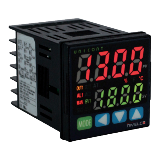
4. WIRING 0/4…20 mA 11 V DC ±2 V Max. load 500 Ω Max. 20 mA Digital input, AL1 output Non-contact, DI-1 DI-1 250 V 3 A AC–1 Contact input Resistive load Output 2 Output 1 Transmitter Relay RS485 (A+) Relay output 250 V 3 A AC–1... - Page 8 1. Measured Value (PV): RUN mode: it shows the currently measured value (PV). Setting mode: it shows the name of the parameter. 2. Set value (SV): RUN mode: it shows the set value (SV). Setting mode: it shows the the parameter value. 3.
-
Page 9: Startup
The characters of the 7-segment display 5.2 STARTUP When energized, the display will flash for one second, at which point all display sections will illuminate. Then the hardware ID code and the input sensor type will flash twice, and the unit will switch to RUN mode. If ‘Open’ is displayed, there is no source or there is a contact error on the universal input. -
Page 10: Sensor Temperature Unit
Input type Accuracy Indication Temperature range (°C) Temperature range (°F) C (TT) C TT 0…2300 32…4172 G (TT) G TT 0…2300 32…4172 LIcH –200…900 –328…1652 L (IC) LIcL –199.9…900.0 –199.9…999.9 UCcH –200…400 –328…752 U (CC) UCcL –199.9…400.0 –199.9…752.0 Platinel II PLII 0…1390 32…2534... -
Page 11: Low-Limit Input Value [Par3 → L-Rg]
Upper scale limit +10% Upper scale limit +5% Upper scale limit Upper limit Lower limit Lower scale limit Lower scale limit –5% Lower scale limit –10% Display PV flashes ±5% section HHHH or LLLL flashes ±5 to 10% section OPEN flashes Over ±10% section 5.3.4 Low-Limit Input Value [PAR3 →... -
Page 12: Input Digital Filter [Par3 → Mavf]
5.3.10 Input Digital Filter [PAR3 → MAvF] Stable control is not possible if the Process Value (PV) fluctuates due to rapid input signal changes. Using the input digital filter function stabilizes the PV for more reliable control. Default setting: 0.1 s. Example: If the digital input filter is set to 0.4 seconds, the digital filter applies to the sampling value collected in 0.4 seconds. -
Page 13: Control Output
5.5 CONTROL OUTPUT Output modes for general temperature control include heating mode or cooling mode and heating and cooling mode. Heating control and cooling control are opposite operations with inverted outputs. The PID time constant varies de- pending on the characteristics of the section controlled during PID control. The value of the control output is MV (Manipulated Variable). -
Page 14: Deadband/Overlap Band [Par2 → Db]
5.5.3 Deadband/Overlap Band [PAR2 → DB] It is possible to assign a deadband between the heating and cooling control bands based on the Set Value (SV) for heating and cooling. A deadband is formed around the SV when a positive (+) value is set. There is no regulation in the deadband, so the heating and cooling MV (Manipulated Variable) will be 0.0% in the deadband formed. - Page 15 When db is in 10 digits Control output MV Heating hysteresis/offset Cooling proportional band 100.0% Cooling control Heating control Process value SV+5 Cooling MV Deadband ON/OFF heating control and PID cooling control When db is in 10 digits Control output MV Heating hysteresis/offset Cooling hysteresis/offset Cooling control...
- Page 16 Control output MV When db is Heating hysteresis/offset Cooling proportional band in -10 digits 100.0% Heating control Cooling control Process value Cooling MV SV-5 Overlap band ON/OFF heating control and PID cooling control Control output MV When db is Heating hysteresis/offset in -10 digits Cooling hysteresis/offset Heating control...
-
Page 17: Mv Upper Limit Value [Par2 → H-Mv] And Mv Lower Limit Value [Par2 → L-Mv]
Control output MV Heating hysteresis/offset When db Cooling proportional band is in 0 digits 100.0% Heating control Cooling control OFF 0.0% (SV) Process value Cooling MV ON/OFF heating control and PID cooling control Control output MV Cooling hysteresis/offset Heating hysteresis/offset When db is in 0 digits Heating control... -
Page 18: Mv Settings For Sensor Break Error [Open] [Par5 → Ermv]
Note: The same MV limits apply during auto-tuning. The MV limits do not apply to manual control, MV when control is stopped, MV sensor failure, and initial manual control. The MV upper / lower limit configuration is not available in the ON / OFF standard control mode (heating or cooling control). -
Page 19: Auto/Manual Control Settings
Ramp operation diagram RAMP RAMP activation zone activation zone RAMP SV = PV RAMP time unit (s/m/h) RAMP setting values (1…9999 digit) RAMP time unit (s/m/h) RAMP SV = PV Time RAMP Start RAMP Start Time Activating RAMP, when RAMP is off RAMP RAMP activation zone... -
Page 20: Initial Mv For Manual Control [Par5 → Itmv]
– Press the button to move the flashing digit (10 → 10 → 10 → 10 → 10 – Select the digit and configure the desired MV value with the buttons 0 → 1 → 2 → 3 → 4 → 5 → 6 → 7 → 8 → 9 → 0 using the buttons. -
Page 21: Initial Mv Manual Control [Par5 → Prmv]
Auto_MV Preset_MV 0.0% 0.0% Time Point of MV change Time Point of MV change Manual control Manual control Switching Switching Power Power failure failure Auto control Auto control Manual control start Manual control end Manual control start Manual control end Auto-MV [AUTO] Preset MV [PrMV] 5.5.7.3 Initial MV Manual Control... -
Page 22: Pid Control [Par3 → C-Md → Pid]
Temperature ON_Offset OFF_Hysteresis Time (t) Control output Cooling control Hysteresis [PAR2 → hHYS/hOFT/cHYS/cOFT] Hysteresis is the setting of the control output on and off point in ON / OFF mode. ON_Hysteresis sets the output to an ON point, and OFF_Offset sets an off point. The values are set in °C / °F. If the hysteresis is set too low, the disturbing characteristics that affect the device (noise, etc.) will turn the output control (compared to the control characteristics) uncertainly on and off, which should be avoided. -
Page 23: Setting The Proportional Band For Heating [Par2 → H-P] And Cooling [Par2 → C-P]
5.6.3.1 Setting the Proportional Band for Heating [PAR2 → H-P] and Cooling [PAR2 → C-P] If the Process Value (PV) is within the proportional band (P), the ON / OFF ratio must be adjusted during the proportional period (T). The defined proportional control (time proportional control) section is called the proportional band. -
Page 24: Auto-Tuning
5.6.4 Auto-Tuning Automatic tuning measures the controlled section’s temperature characteristics and thermal response rate and then determines the required PID time constants. (If the [C-MD] control type is PID, it is displayed.) This operation will stop automatically if an [OPEN] error occurs during auto-tuning. To stop auto-tuning, change the setting to OFF. -
Page 25: Alarm Output
5.7 ALARM OUTPUT There are three alarms that operate separately. In addition, the combined alarm operation and alarm option can be set. Use the digital input setting as [AlRE] or turn off the unit and restart the unit to clear the alarm operation. 5.7.1 Alarm Operation [PAR4 →... -
Page 26: Alarm Output Settings [Par4 → Al1T]
If the PV is higher than the Absolute value absolute value, the output PV[[ upper limit 100 °C 110 °C will turn on. 90 °C 100 °C The absolute value alarm alarm can be set in AL1H. Absolute value of alarm: Absolute value of alarm: set to 90 °C set to 110 °C... -
Page 27: Alarm Output Lower [Par1 → Al1L] And Upper [Par1 → Al1H] Limit Value Settings
– Condition of standby sequence 2, alarm latch and repeated standby mode of standby sequence 2 again: switch on, change set temperature, alarm temperature [AL1] or alarm operation [AL-1], switch STOP mode to ″Normal″ mode. Note: If the alarm operation is set to loop break alarm [LBA], sensor fault alarm [SBA] or heating fault alarm [HBA], only the standard alarm [AL-A] and alarm interlock [AL-C] will be displayed. -
Page 28: Loop Break Alarm (Lba) [Par4 → Al-1/ → Lba]
Temperature Alarm temperature Hysteresis Time Without Preset Delay: Alarm Output With Preset Delay: Alarm Output Alarm off Parameter Description Alarm Output 1 on Delay: In the event of an alarm event, it is on standby for a preset period of time, A1ON checks the conditions for activating the alarm, and turns on the alarm output if the conditions persist. -
Page 29: Lba Monitoring Period [Par4 → Lbat]
When performing auto-tuning, the LBA detection band [LBaB] and LBA monitoring time [LBaT] are automatically set based on the auto-tuning value. For AT (auto-tuning) / manual control / stop control, the loop break alarm [LBA] does not work. 5.7.8 LBA Monitoring Period [PAR4 →... -
Page 30: Sensor Break Alarm [Par4 → Al-1 → Sba]
Start If the MV control output is 100%, the PV exceeds the LBA detection band [LBaB] during the LBA … monitoring time [LBaT]. MV control output change status (LBA supervision time resets) … If the MV control output is 0% and the PV does not fall below the LBA detection band [LBaB] during the LBA monitoring time [LBaT], the loop break alarm (LBA) will turn on after the LBA monitoring time ... -
Page 31: Alarm Output Deactivation [Par5 → Di-K→ Alre]
Heater burnout detection settings [PAR1 → AL1L] Set the alarm output value [AL1L] as the reference value to detect the heater burnout. Default setting: 0.0. Unit: A. Note: Set to 0.0 to turn off. Set to 50.0 to turn on. Calculation of setting value Heating burnout set value = {(normal heating current) + (heating burnout current)} / 2 Example: If two output heaters (200 V AC, 1 kW, 5 A) are used, the normal heating current is 10 A (5 A ×... -
Page 32: Alarm Output Examples
5.7.13 Alarm Output Examples Absolute upper limit alarm and deviation upper limit alarm Temperature Upper-limit Alarm Setting (Absolute Value or Offset Hysteresis Value) Power On Time Standard alarm Alarm Latch ● ○ Standby Sequence Alarm Latch and Standby Sequence Minimum Signal Band Alarm Reset Signal Alarm Latch... -
Page 33: Analog Transmission
Deviation upper / lower limit alarm (hysteresis overlap) Power Failure (Power OFF Point) Power ON (restore) Point Temperature Upper-limit Alarm Setting Hysteresis Setting Value Low-limit Alarm Setting Power ON Time Standard Alarm Alarm Latch Standby Sequence ● ○ Alarm Latch and Standby Sequence Alarm Reset Signal Alarm Latch... -
Page 34: Unit Address Settings [Par4 → Adrs]
Interface: Type Description Communication protocol Modbus RTU Connection type RS485 Application standard EIA RS485 compliant Maximum number of connections 31 unit (address: 01…99) Synchronization method Asynchronous Communication method 2-wire, half-duplex Communication distance Max. 800 m Communication speed 2400, 4800, 9600, 19200, 38400 bps Communication response time 5…99 ms Start bit... -
Page 35: Enable / Disable Communication Writing [Par4→ Comw]
5.9.6 Enable / Disable Communication Writing [PAR4→ COMW] This function can change the parameter settings stored in the memory with the PC, GP, PLC, etc. to enable or disable writing. Default setting: EnA. Setting Description Enable parameter set / modification via communication. DIsA Prohibit the setting or modification of parameters by communication. -
Page 36: Stop Control Output Settings
Note: Ignores the MV of the ON / OFF control or the PID control and sends a control value based on the defined MV. 5.10.4.2 Stopping the Alarm Output [PAR5 → StAL] Enable or disable the alarm output when the control stopped. Default setting: CONT. Setting Description The alarm stops under all conditions. -
Page 37: Digital Input Button Setting [Par5 → Di-K]
5.10.6.2 Digital Input Button Setting [PAR5 → DI-K] To use the digital input button function, all functions must be first be assigned to the buttons. Default setting: STOP. Setting Description STOP RUN / STOP AlRE Deactivate forced alarm output Automatic tuning RUN / OFF (for PID control) Not used Note: If the digital input button and the digital input terminal are set the same, the digital input button will not work. -
Page 38: Password Settings [Par5 → Pwd]
5.10.11.2 Reset Password Entering an incorrect password displays the encrypted form of the password on the SV display. Send this code to NIVELCO to recover a lost password. Incorrect password entry (for example, the correct password is 1234). 1. Access to the SV parameter or parameter group. -
Page 39: Error Codes
6. ERROR CODES The controller diagnoses the input signals for errors and displays the messages accordingly. These messages inform the user of device problems. When the input value returns to the appropriate range, the alarm is deactiva- ted and the device returns to normal operation. Message Input Description Output... -
Page 40: Maintenance, Repair, And Storage
(Returned Equipment Handling Form) must be filled and enclosed in the parcel. Download it from our website www.nivelco.com. The device must be sent back with a declaration of decontamination. A statement must be provided in the declaration that the decontamination process was successfully completed and that the device is clean from any hazardous substances. -
Page 41: Menu Map
8. MENU MAP RUN mode 3 sec. Press any key among 2 sec. once. When PW is valid. Control output RUN/STOP Auto-tunning RUN/STOP Input type Alarm output 1 operation mode Multi SV Set the set value. 1.5 sec. 1.5 sec. 1.5 sec.
Need help?
Do you have a question about the UNICONT PMG-500 and is the answer not in the manual?
Questions and answers