
Summary of Contents for Mini?Cam PCB-001-388
- Page 1 PCB-001-388 MULTI-FREQUENCY SONDE TECHNICAL SUPPORT DOCUMENT MINI-CAM InPipe Innova on www.minicam.co.uk REVISION A (09/2017)
-
Page 2: Table Of Contents
TABLE OF CONTENTS PCB-001-388 • PRODUCT OVERVIEW Page 1 • CONNECTION DIAGRAM Page 2 • PROGRAMMING Page 3-8 Programming Set-Up Page 3 Using Dataman IDE for programming Page 4&5 Fault Resolu on 1 - Device Fails Blank Check Page 6&7... -
Page 3: Product Overview
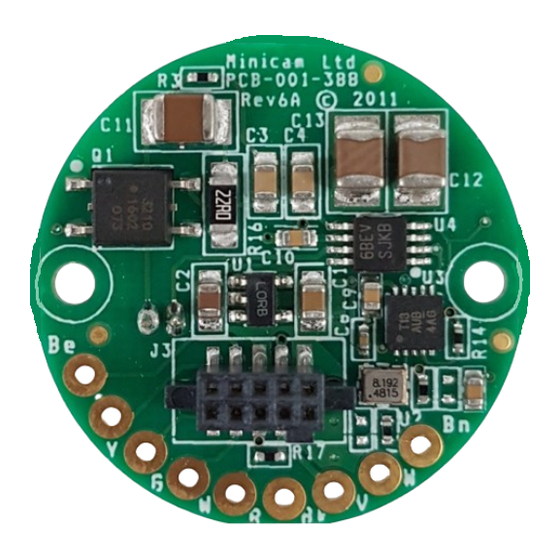
PRODUCT OVERVIEW PCB-001-388 Market requirements and materials used for pipes vary globally. Mini-Cam’s Mul -Frequency Sonde is designed to provide the user with the ability to choose, via the SOLOPro CCU, the frequency required to aid loca ng the camera in differing pipe materials. -
Page 4: Connection Diagram
CONNECTION DIAGRAM PCB-001-388 SONDE CONTROL LIGHTS (+) 1v, 2v, 3.3v BLUE WIRE +24v VIDEO LIGHTS (-) WHITE WIRE YELLOW WIRE CAMERA (+) RED WIRE BLACK WIRE +12V (0v) SONDE AERIAL REVISION A (09/2017) PAGE 2... -
Page 5: Programming
Equipment Required Power Supply Oscilloscope PCB-001-388 Programming / Test Adapter Dataman 40PRO PC with ‘Dataman-PRO PG40W’ Independent Development Environment installed The diagram shown below shows the setup, note the power supply is set to 12v, ensure that the power supply is set to output the voltage... - Page 6 Open the ‘Pan and Rotate camera’ folder, now open the ‘Board level’ folder. Open the file named… ‘PCB-001-388 rev6A analogue sonde.eprj’. The IDE will now load the correct seMngs for the device. Ensure the correct programmer ‘Dataman-40PRO’ is connected, refer to the bo?om of the IDE…...
- Page 7 PROGRAMMING PCB-001-388 The menu should have closed and been replaced with a smaller status box accompanied by another box en tled ‘In circuit programming’, see ‘Fig 1’. Ensure the PCB and the pogos have formed a connec on by applying light pressure to the PCB taking care to not cause any bending.
- Page 8 PROGRAMMING PCB-001-388 Fault Resolu4on Device fails ‘Blank Check’. The image shows a blank checking failure in the programming process. This will appear if device has been previously programmed or failed to program part way through & it will need to be erased before being reprogrammed.
- Page 9 PROGRAMMING PCB-001-388 The menu should have closed and been replaced with a smaller status box accompanied by another box en tled ‘In circuit programming’, see ‘Fig 1’. Ensure the PCB and the pogos have formed a connec on by applying light pressure to the PCB taking care to not cause any bending.
-
Page 10: Fault Resolu On 2 - Supply Voltage Out Of Range (3Mv)
PROGRAMMING PCB-001-388 Fault Resolu4on Supply voltage out of range (3mV) This fault will occur if voltage is not supplied to the on board microcontroller. There is more than one reason this could happen… 12v is not being supplied to the jig. -
Page 11: Testing Methods
TEST METHODS PCB-001-388 Oscilloscope - General User Guide Mul purpose Dial - When a menu is open, use this dial to navigate through the op ons. Press down on the middle of the dial to make a selec on. Ver cal Posi on - Turn the dial to change where the waveform is posi oned ver cally to be?er fit the graph and ease the difficulty of any manual measurements. -
Page 12: Method 1 - Tes Ng With Jig
Oscilloscope Voltage Probe with 10X capability PCB-001-388 Programming / Test Adapter The images below show the setup, note the power supply is set to 12v, ensure that the power supply is set to output the voltage. Give special a?en on to the probe connec ons to be sure they are not crea ng a short... -
Page 13: Method 2 - Tes Ng With Pcb Fi?Ed To Coiler
TEST METHODS PCB-001-388 Method 2 - Tes4ng The PCB Fi9ed To A Coiler Equipment Required Oscilloscope Voltage Probe with 10X capability Ensure the PCB is accessible by removing any skid assemblies and then the camera. Turn on the CCU and make sure the link cable is connec ng the CCU to the Coiler. -
Page 14: Method 3 - Tes Ng With 2 Power Supplies
TEST METHODS PCB-001-388 Method 3 - Tes4ng With 2 Power Supplies Equipment Required Power Supply (x2) Oscilloscope Voltage Probe with 10X capability Make sure the PCB is disconnected from the system. Make sure an aerial is connected. Set the first power supply to 12v and connect to the ‘R’ & ‘Bk’... -
Page 15: Expected Results 1 - 512Hz Tested
TEST METHODS PCB-001-388 Expected Results Below is the 512Hz measurement, when tes ng the PCB the waveform displayed should look very similar to this. If it does not, something is wrong. Check connec ons & seMngs, if they are correct there is a fault condi on.. -
Page 16: Expected Results 2 - 640Hz Tested
TEST METHODS PCB-001-388 Expected Results Below is the 640Hz measurement, when tes ng the PCB the waveform displayed should look very similar to this. If it does not, something is wrong. Check connec ons & seMngs, if they are correct there is a fault condi on.. -
Page 17: Expected Results 3 - 33Khz Tested
TEST METHODS PCB-001-388 Expected Results Below is the 33kHz measurement, when tes ng the PCB the waveform displayed should look very similar to this. If it does not, something is wrong. Check connec ons & seMngs, if they are correct there is a fault condi on.. -
Page 18: Circuit Schematic
SCHEMATIC DIAGRAM PCB-001-388 REVISION A (09/2017) PAGE 16... -
Page 19: Pcb Change History
PCB CHANGE HISTORY PCB-001-388 Changes made between Versions 2A and 3A - 21/07/10 (PCB revision) 1. Remove Op-Amps & Filter. Replaced with dual gate driver 2. Remove switchable low frequency parallel tuned circuit 3. Replace 6 way JST ZR connector with individual cable termina ons 4. -
Page 20: Document Change History
DOCUMENT CHANGE HISTORY PCB-001-388 DOCUMENT VERSION PAGE REV A REV B REV C REV D REV E REV F REVISION A (09/2017) PAGE 18...
Need help?
Do you have a question about the PCB-001-388 and is the answer not in the manual?
Questions and answers