Advertisement
MAXPRO TECHNOLOGIES, INC.
REPAIR AND REBUILD MANUAL
DIS-ASSEMBLY
1. Remove snap ring, #17, from the spool valve housing, # 9.
2. With a long screw driver or wooden dowel, from the ½" FNPT side of the housing, #9, push
out the spool plug, #15, and spool, #12, from the housing.
3. Remove the four (4) cap screws, #21, that hold the housing to the top cap, #1, and remove
housing.
4. Holding the housing in a vise, use special tool, P/N 101-0033, to remove the spool sleeve,
#10, from the housing. DO NOT SCRATCH THE BORE OF THE SLEEVE.
5. Remove both tappet screws, #2, from both ends of the amplifier. With needle nose pliers,
remove the springs, #4, and tappets, #5 from the end caps
6. Using a 3/4" socket or open end wrench, remove the four (4) tie rods, #50, and pull both end
caps away from the air cylinders, # 28 and #48.
7. Push either of the air pistons, #43, all the way to one side, on the side where the piston is
closest to the center air separation plate, #29, tap on the outside of the air cylinder, #28 or
#48, near the end, with your hand or a soft hammer, and remove cylinder from piston.
Push the piston to the opposite side and repeat the procedure to remove the other
cylinder.
8. Using a 15/16" socket and open end wrench, remove one of the nuts, #45, from the piston rod,
#41, and remove the piston from the rod. Both pistons do not have to be removed from
the rod. Pull the piston and rod from the center air separation plate, #29.
9. Remove the snap rings, #36, that hold the four (4) check valve assemblies in place and remove
the check seats, #30, O-Rings, #31, plates, #32, springs, # 33, holders, #34, and retainer
rings, #35.
10. Remove all old O-Rings and seals. Clean all other parts in mineral spirits to remove all dirt
and grease.
NOTE!! Before re-assembling, inspect all parts for damage, such as scratches on the
ASSEMBLY
1. Start with the check valve assemblies. Refer to the attached drawing 3630.0658 for an
expanded view of the parts and their orientation for proper order of assembly.
Use a small amount of grease on all O-Rings. Note that the angle side of the seats face the
plate. The two (2) check valve assemblies that are on the inlet, or "A" side, have the seat
installed first, then the O-Ring, check plate, spring, holder, retaining ring and snap ring.
On the outlet, or "B" side, the order is opposite, starting with the holder, then the spring,
check plate, O-Ring, seat, retaining ring and snap ring.
7728 Klier Dr.
Fairview, Pa. 16415
Phone: 814-474-9191
Fax:
814-474-9391
for
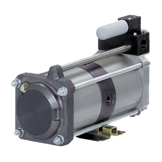
AIR AMPLIFIER
Model #
bores of cylinders and spool sleeves and surfaces of the piston rod.
GPLV2
Advertisement
Table of Contents

Summary of Contents for MaxPro GPLV2
- Page 1 MAXPRO TECHNOLOGIES, INC. 7728 Klier Dr. Fairview, Pa. 16415 Phone: 814-474-9191 Fax: 814-474-9391 REPAIR AND REBUILD MANUAL AIR AMPLIFIER GPLV2 Model # DIS-ASSEMBLY 1. Remove snap ring, #17, from the spool valve housing, # 9. 2. With a long screw driver or wooden dowel, from the ½" FNPT side of the housing, #9, push out the spool plug, #15, and spool, #12, from the housing.
- Page 2 2. Install the O-Rings, #46, in the pistons, #43, then install the seals, #47, on the pistons, over the O-Rings. The seals can be installed on the pistons by starting them on one side of the piston, then insert a length of plastic banding material under the seal. The seal can then be worked around until it is in place all around the piston.
- Page 3 MAXPRO TECHNOLOGIES, INC. 7728 Klier Drive Fairview Pa. 16415 Phone: 814-474-9191 Fax: 814-474-9391 SUGGESTED PREVENTATIVE MAINTENANCE FOR AIR DRIVEN AIR AMPLIFIERS The suggested maintenance schedule is intended only as a guideline. The operating conditions of the amplifier, such as air drive pressure, air supply pressure, air outlet pressure, air cleanliness and actual running time at pressure, combine for an almost infinite range of variable conditions and all directly relate to the life of the amplifier and it’s components.
Need help?
Do you have a question about the GPLV2 and is the answer not in the manual?
Questions and answers