Table of Contents
Advertisement
Quick Links
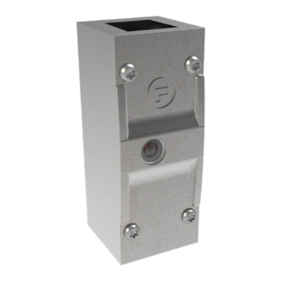
Operating Instructions: Stop - Non Solenoid Switch Body
Description
The S40Stop is a robust, heavy duty, safety switch unit. When properly installed,
it provides safe access and control for a variety of machinery. This unit may be in-
stalled in any orientation. The unit is ready to accept a variety of modules from the
amGardS40 range, which will enable it to be used in many applications. Safety
switch interlock for use in S40 range.
• Dual force break normally closed safety circuits.
• Single normally open monitor contact.
• LED status indication.
• PLe.
• Stainless steel construction.
• IP69K.
Note: If, as a result of risk assessment, it cannot be discounted that persons can be enclosed within a danger zone, then
guard locks with additional removable keys (safety keys) must be used or comparable measures must be taken - GS ET 19.
Options & Ordering Information
Description
Standard
Standard
Standard
Important:
This product is designed for use according to the installation and operating instructions enclosed. It must be installed
by competent and qualified personnel who have read and understood the whole of this document prior to commencing
installation. If the equipment is used in a manner not specified by the manufacturer, the protection provided by the equipment
may be impaired. Any modification to or deviation from these instructions invalidates all warranties. Fortress Interlocks Ltd
accepts no liability whatsoever for any situation arising from misuse or misapplication of this product. This product is not to
be used as a Mains Isolator or Emergency Stop. The unit is a component to be added to a permanent electrical installation
meeting the requirements of the applicable IEC/EN standards. This product meets the requirements of the standard EN ISO
14119 – Safety of machinery, interlocking devices associated with guards. Principles for design and selection.
The voltages used within the S40Stop circuits must all be of the same type. i.e. ALL Hazardous Live or ALL Machine
Extra Low Voltage.
Note: The availability of spare Actuators and Keys makes it possible to easily bypass the safety devices and, for
this reason, the security of any spare Actuators and Keys must be effectively monitored. Where applicable, the
same also applies for Keys used for resetting after an Escape Release or Manual Override.
BEWARE OF INTENTIONAL MISUSE CAUSED BY OPERATORS WANTING TO BYPASS SAFETY SYSTEMS. THE
INSTALLER SHOULD ASSESS THE RISKS AND MITIGATE AGAINST THEM.
IF YOU HAVE ANY QUESTIONS OR QUERIES OF ANY NATURE WHATSOEVER PLEASE CONTACT THE SUPPLIER
WHO WILL BE PLEASED TO ADVISE AND ASSIST.
Control Voltage
24V AC/DC
110V AC
230V AC
1
Gard
Part No.
S40ST401
S40ST101
S40ST201
Advertisement
Table of Contents

Related Manuals for Halma FORTRESS am Gard S40ST401

Summary of Contents for Halma FORTRESS am Gard S40ST401
- Page 1 Gard Operating Instructions: Stop - Non Solenoid Switch Body Description The S40Stop is a robust, heavy duty, safety switch unit. When properly installed, it provides safe access and control for a variety of machinery. This unit may be in- stalled in any orientation. The unit is ready to accept a variety of modules from the amGardS40 range, which will enable it to be used in many applications.
- Page 2 Operating Instructions: Stop - Non Solenoid Switch Body amGardS40 Stop Technical Specification Housing Materials Stainless Steel to BS3146 ANC4B Electrical Specification - AC 50/60Hz/DC Ingress Protection IP67 & IP69K Mechanical Life 1,000,000 Switching Cycles Performance Level B10d 5,000,000 Ambient Temperature -20°C to + 60°C (-4°F to 140°F)* Maximum Altitude 2000m...
- Page 3 Operating Instructions: Stop - Non Solenoid Switch Body Figure 1: Dimensional Drawing - SWITCH PLUNGER M4 X 30 HEAD SCREWS EARTH POINT Figure 2: Dimensional Drawing -...
- Page 4 Operating Instructions: Stop - Non Solenoid Switch Body Tools and Fixings Required Pin Hex Driver Bit (Provided) 1/4” Driver (to suit above) Ø8.2mm Drill or M5 Drill and Tap 3.5mm Flat Blade Electrical Screwdriver 4 x M8 screws for rear-fixing. (Screws must be suitable length for a minimum of 10mm thread engagement with Stop module.
- Page 5 Operating Instructions: Stop - Non Solenoid Switch Body Electrical Connection Terminal Arrangement 1. Check that the complete Guard Interlocking Device to be installed is of the same electrical type and voltage rating as the machine control circuits. This information can be found on a label, fixed to the device. Note that all device are designed to operate at +/-10% of the nominal supply voltage.
- Page 6 Operating Instructions: Stop - Non Solenoid Switch Body Service and Inspection Regular inspection of the following is necessary to ensure trouble-free, lasting operation: • Correct operating function • Secure mounting of components • Debris and wear • Sealing of cable entry •...
Need help?
Do you have a question about the FORTRESS am Gard S40ST401 and is the answer not in the manual?
Questions and answers