Table of Contents
Advertisement
Quick Links
Advertisement
Table of Contents

Summary of Contents for Plexon PlexBright Light
- Page 1 PlexBright Light Measurement Kit Guide ® www.plexon.com...
-
Page 2: Table Of Contents
September 2018 OPTTN0002e -Removed wand detector June 2014 OPTTN0002d - Minor edits May 2014 OPTTN0002c - Updated images and minor edits March 2014 OPTTN0002b - Additional copy and minor edits November 2013 OPTTN0002a - Initial creation of document www.plexon.com Page 2... -
Page 3: Introduction
Different power meter/photodetector combinations will enable measurements of PlexBright light outputs, but the wrong components or even the incorrect use of the right components may lead to inaccurate measurements. -
Page 4: Components
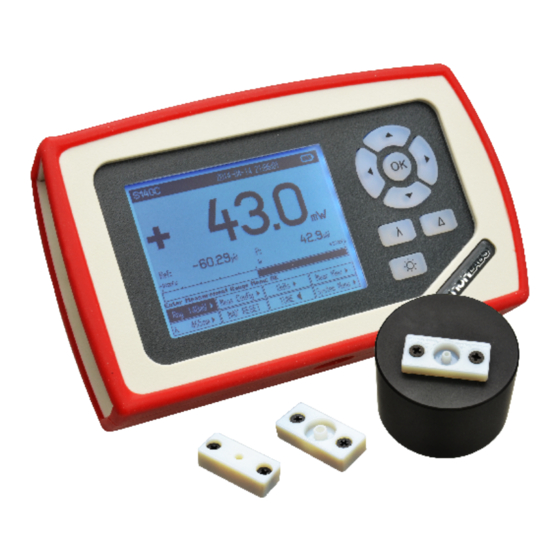
The PlexBright Light Measurement Kit contains the following light measurement hardware from THORLABS as well as custom Plexon adaptors required for accurate and simple measurements of light output from PlexBright LED Modules, PlexBright Optical Patch Cables or PlexBright Fiber Stub Implants. -
Page 5: Hardware Set-Up
THORLABS System Equipment 1. Unpack the S140C Photodetector from the storage case. 2. Use a Phillips screwdriver (not included) to remove any non-Plexon adaptors from the S140C Photodetector, returning them to the storage case for possible future use. 3. Unpack the PM100D Power Meter from its storage case. -
Page 6: Preparing Plexbright Equipment To Be Measured
Equipment contained in a white Plexon box. 2. Use a Phillips screwdriver (not included) to attach the desired PlexBright Photodetector Adaptor to the S140C Photodetector with the included screws (review “Plexon Photodetector Adaptors” options in previous Components section). Preparing PlexBright Equipment to be Measured The PlexBright Photodetector Adaptors are designed to easily and accurately interface PlexBright LED Modules and PlexBright Optical Patch Cables to the THORLABS S140C Photodetector. - Page 7 - For PlexBright Compact LED Modules, the LC Photodetector Adaptor (08-14-A-01) should already be attached (see “Plexon Photodetector SMA-to-BNC Adaptors Box” section under “Hardware Setup”). - For PlexBright Table-top LED Modules, the FC Connector Photodetector Adaptor (08-14-A-02) should already be attached (see “Plexon Photodetector SMA-to-BNC Adaptors Box” section under “Hardware Setup”). www.plexon.com...
- Page 8 PlexBright Photodetector Adaptor already fixed to the photodetector: - For PlexBright Optical Patch Cables with an LC Ferrule Tip, the LC Photodetector Adaptor (08-14-A-01) should already be attached (see “Plexon Photodetector SMA-to-BNC Adaptors Box” section under “Hardware Setup”). - For PlexBright Optical Patch Cables with an FC Ferrule Tip, the FC Ferrule Photodetector Adaptor (08-14-A-03) should already be attached (see “Plexon Photodetector SMA-to-BNC Adaptors Box”...
-
Page 9: Measuring Steady-State Light Outputs
OK button to enter editing mode. In edit mode, use the arrow keys to set the desired wavelength and then press OK. NOTE: Failure to set the appropriate wavelength will result in faulty readings of light output. Select the wavelength of the light being measured www.plexon.com Page 9... -
Page 10: Dynamic/Pulsed Light Measurements
However, the PM100D Power Meter provides an analog output signal that can be routed to an oscilloscope to characterize dynamic light outputs. The following materials are required: SMA-to-BNC Adaptor (included) Standard female-to-female BNC cable (not included) Standard oscilloscope (not included) Sample Oscilliscope www.plexon.com Page 10... - Page 11 3. Select the wavelength being measured as described in the Measuring Steady-state Light Outputs section. 4. Under the “Measurement Configuration” menu of the PM100D Power Meter’s push button interface, select the “BW HI” (high bandwidth) option. This option will enable high frequency outputs. www.plexon.com Page 11...
- Page 12 When an oscilloscope is not available, the maximum value reading on the front display of the light meter (MAX RESET) may be used to capture the peak value of quickly changing light pulses. For further information, consult Section 5.3: Power Measurement of Pulsed Signals in the THORLABS PM100D Operation Manual. www.plexon.com Page 12...
-
Page 13: Appendix: Avoiding Light-Clipping With Plexbright Photodetector Adaptors
Left) The adaptor is designed to measure a narrow output cone of light. Right) Wider angle light is clipped by the same adaptor and never reaches the photodetector surface. www.plexon.com Page 13... - Page 14 For Sales Support, email info@plexon.com or call +1 (214) 369-4957. Technical Support If after reviewing this document, you would still like to access Plexon’s Technical Support, we are available via several communication channels. You are invited to reach us through email or on the phone.
Need help?
Do you have a question about the PlexBright Light and is the answer not in the manual?
Questions and answers