Table of Contents
Advertisement
Quick Links
Advertisement
Table of Contents

Related Manuals for ALTUS Nexto Xpress


Summary of Contents for ALTUS Nexto Xpress
- Page 1 User Manual Nexto Xpress MU216600 Rev. L February 23, 2021...
- Page 2 General Supply Conditions No part of this document may be copied or reproduced in any form without the prior written consent of Altus Sistemas de Automação S.A. who reserves the right to carry out alterations without prior advice. According to current legislation in Brazil, the Consumer Defense Code, we are giving the following information to clients who use our products, regarding personal safety and premises.
-
Page 3: Table Of Contents
CONTENTS Contents Introduction ........... . . 1.1. - Page 4 CONTENTS 3.3.3. Network Cable Installation ........27 3.4.
- Page 5 ......... . . 102 5.10.2. SNMP in Nexto Xpress Controllers ....... 102 5.10.3.
- Page 6 CONTENTS Maintenance ........... . . 106 6.1.
-
Page 7: Introduction
CANopen Manager protocol. It can also be expanded using other available ports like Ethernet and RS-485. Nexto Xpress is suitable for small applications and remote distributed I/O. It may be applied in verticals such as infrastruc- ture, building automation, water, wastewater, food, textiles, factory automation, machines and several other OEM solutions. -
Page 8: Documents Related To This Manual
1.1. Documents Related to this Manual This manual will focus on information that is specific for the controllers of Nexto Xpress family. For other functionalities that are identical along all controllers of Nexto Series, this manual will just point to the corresponding manual of Nexto Series that contains the information. -
Page 9: Technical Support
1. INTRODUCTION 1.3. Technical Support For Altus Technical Support contact in São Leopoldo, RS, call +55 51 3589-9500. For further information regarding the Altus Technical Support existent on other places, see https://www.altus.com.br/en/ or send an email to altus@altus.com.br. If the equipment is already installed, you must have the following information at the moment of support requesting: The model of the used equipments and the installed system configuration... -
Page 10: Technical Description
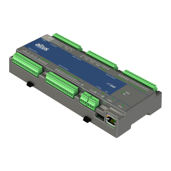
Figure 2: XP325 front panel The front panel contains the identification of the I/O and communication interfaces available on Nexto Xpress controllers. The digital I/O interfaces have one LED for each point to indicate the logic state, while the communication interfaces have one LED each to indicate activity. -
Page 11: Product Features
2. TECHNICAL DESCRIPTION 2.2. Product Features 2.2.1. General Features XP300 XP315 XP325 XP340 Digital Inputs Fast Inputs Digital Outputs Fast Outputs Max. number of high-speed counters Max. number of external interruptions Max. number of PTO outputs Max number of VFO/PWM outputs V/I analog inputs (AI) RTD analog inputs (AI) V/I analog outputs (AO) - Page 12 2. TECHNICAL DESCRIPTION XP300 XP315 XP325 XP340 Digital Outputs to all 1,500 Vdc / 1 minute (1,000 Vac / 1 minute) Maximum power dissipation 0.5 mm (20 AWG) with ferrule Maximum wire size 1.5 mm (16 AWG) without ferrule Minimum wire temperature rating 75 C Wire material Copper only...
- Page 13 2. TECHNICAL DESCRIPTION Command Symbolic Variable Retain variable Persistent variable Reset warm / Power-on/off cycle Reset cold Reset Origin Download Online change Reboot PLC Clean All Reset Process (IEC 60870- 5-104) Table 4: Post-command Variable Behavior Notes: Maximum number of tasks: This value represents the maximum total of user and system tasks. The detailed description of possible user tasks can be found on Project Profiles section of User Manual.
-
Page 14: Can
2. TECHNICAL DESCRIPTION 2.2.3. CAN Connector 3-pin terminal block Physical interface CAN bus Supported standards CAN 2.0A 2.0B (11-bit and 29-bit identifiers) Max. number of nodes Termination Yes (Configurable) Baud rate 10, 20, 50, 100, 125, 250, 500, 800, 1000 kbit/s CANOpen Manager (Master) Protocols CANOpen Slave... -
Page 15: Ethernet
2. TECHNICAL DESCRIPTION 2.2.5. Ethernet Ethernet Connector Shielded female RJ45 Auto crossover Maximum cable length 100 m Cable type UTP or ScTP, category 5 Baud rate 10/100 Mbps Physical layer 10/100 BASE-TX Data link layer Network layer Transport layer TCP (Transmission Control Protocol) UDP (User Datagram Protocol) MODBUS TCP Client and Server MODBUS RTU Master/Slave... -
Page 16: Power Supply
2. TECHNICAL DESCRIPTION 2.2.6. Power Supply Power Supply Nominal input voltage 24 Vdc Input voltage 19.2 to 30 Vdc Maximum input current (in- 50 A / 300 us rush) Maximum input current 300 mA Table 9: Power Supply Features 2.2.7. Digital Inputs Digital Inputs Input type Optoisolated sink type 1... -
Page 17: Fast Inputs
2. TECHNICAL DESCRIPTION 2.2.8. Fast Inputs Fast Inputs 4 (can be used as high-speed counter, External interrupt or Number of fast inputs normal input) Max. number of high-speed counters Max. number of external in- terrupts Connector configuration I00, I01, I02 and I03 24 Vdc Input voltage 15 to 30 Vdc for logic level 1... -
Page 18: Digital Outputs
2. TECHNICAL DESCRIPTION 2.2.9. Digital Outputs Digital Outputs Output type Optoisolated transistor source type Maximum output current 1.5 A per output 12 A total Leakage current 35 A On state resistance 105 mΩ External power supply 19.2 to 30 Vdc Switching time 20 s - off-to-on transition @ 24 Vdc 500 s - on-to-off transition @ 24 Vdc... -
Page 19: Fast Outputs
2. TECHNICAL DESCRIPTION 2.2.10. Fast Outputs Fast Outputs Number of outputs 4 (can be used as VFO/PWM, PTO or normal output) Max. number of PTO outputs 4 when using no PTO Max number of VFO/PWM 2 when using 1 PTO outputs 0 when using 2 PTO Connector configuration... -
Page 20: Analog Inputs
2. TECHNICAL DESCRIPTION 2.2.11. Analog Inputs Analog Inputs Input type Voltage or current input, single ended, individually configured Data format 16 bits in two’s complement, justified to the left Converter resolution 12 bits monotonicity guaranteed, no missing codes Conversion time 400 s (all V/I and RTD channels enabled) Input state indication Module protections... - Page 21 2. TECHNICAL DESCRIPTION Current Input Mode Input ranges Range Engineering Scale Resolution 0 to 20 mA 0 to 30,000 5.12 A 4 to 20 mA 0 to 30,000 5.12 A Precision 0.3 % of full scale @ 25 C 0.015 % of full scale / C Over scale 3 % of full scale Maximum input current...
-
Page 22: Analog Outputs
2. TECHNICAL DESCRIPTION 2.2.12. Analog Outputs Analog Outputs Output type Voltage or current output, individually configured Data format 16 bits in two’s complement, justified to the left Converter resolution 12 bits monotonicity guaranteed, no missing codes Update time 450 s (all outputs enabled) Output state indication Module protections Yes, protection against surge voltages and polarity inversion... -
Page 23: Compatibility With Other Products
2.3. Compatibility with Other Products To develop an application for Nexto Xpress controllers, it is necessary to check the version of MasterTool IEC XE. The following table shows the minimum version required (where the controllers were introduced) and the respective firmware... -
Page 24: Time For Instructions Execution
2. TECHNICAL DESCRIPTION 2.4.3. Time for Instructions Execution The below table presents the necessary execution time for different instructions in Nexto Xpress CPUs. Instruction Language Variables Instruction Times ( s) 1000 Contacts BOOL REAL 1000 Divisions REAL REAL 1000 Multiplications... -
Page 25: Physical Dimensions
2. TECHNICAL DESCRIPTION 2.5. Physical Dimensions Dimensions in mm. Figure 3: XP3xx Physical Dimensions... -
Page 26: Purchase Data
High-Speed Compact PLC with 16 DI, 16 DO Transistor, 5 V/I AI, 2 XP340 RTD AI (3 wire), 4 AO, 1 Ethernet, 1 RS-485 Serial, CANopen Master and user web pages support Table 23: Nexto Xpress Controller Models 2.7. Related Products The following products must be purchased separately when necessary: Code... - Page 27 AL-2306: Two shielded twisted pairs cable without connectors, used for networks based on RS-485 or CAN. AL-1766: Cable with a female DB9 connector and terminals for communication between HMI P2 and Nexto Xpress/NX3003 controllers.
-
Page 28: Installation
3.1. Mechanical Installation Nexto Xpress controllers were designed to be installed in a standard DIN rail. Additionally, the user shall provide a suitable enclosure that meets the system protection and safety requirements. The next sections shows the procedures for installing and removing the controller. - Page 29 3. INSTALLATION Figure 5: Fixing the controller on the DIN rail Finally, move the two locks to closed position to lock the controller on the DIN rail, as shown on the figure below: Figure 6: Locking the controller on the DIN rail...
-
Page 30: Removing The Controller
3. INSTALLATION 3.1.2. Removing the controller To remove the controller from the DIN rail, just move the two locks to the open position as shown on the figure below: Figure 7: Unlocking the controller from the DIN rail... -
Page 31: Electrical Installation
3. INSTALLATION 3.2. Electrical Installation DANGER: When executing any installation in an electric panel, certify that the main energy supply is OFF. Figure 8: XP3xx Electrical Installation Diagram... - Page 32 3. INSTALLATION Diagram Notes: 1. Typical connection of analog output on voltage/current mode 2. Typical connection of digital output (source type) 3. External power supply to supply outputs Q00 to Q17, terminals Q + must be connected to +24 Vdc, and terminal Q- must be connected to 0 Vdc 4.
-
Page 33: Ethernet Network Connection
The Ethernet network connection uses twisted pair cables (10/100Base-TX) and the speed detection is automatically made by the Nexto Xpress controller. This cable must have one of its endings connected to the interface that is likely to be used and another one to the HUB, switch, microcomputer or other Ethernet network point. -
Page 34: Serial Rs-485 And Can Network Connection
3. INSTALLATION Figure 9: RJ45 Female Connector Signal Description TXD + Data transmission, positive TXD - Data transmission, negative RXD + Data reception, positive Not used Not used RXD - Data reception, negative Not used Not used Table 26: RJ45 Female Connector Pin out The interface can be connected in a communication network through a hub or switch, or straight from the communication equipment. -
Page 35: Initial Programming
4. INITIAL PROGRAMMING 4. Initial Programming The main goal of this chapter is to help the programming and configuration of Nexto Xpress controllers, allowing the user to take the first steps before starting to program the device. Just like for the other devices of Nexto Series, the programming of Nexto Xpress controllers is made through the MasterTool IEC XE (IDE) development interface, which offers a full IEC 61131-3 programming system with all languages defined by this... - Page 36 4. INITIAL PROGRAMMING SIGNIFICANCE OVERLAPPING Byte Word DWord LWord Byte Word DWord %QX0.7 %QX0.6 %QX0.5 %QX0.4 %QB00 %QX0.3 %QX0.2 %QX0.1 %QX0.0 %QX1.7 %QX1.6 %QX1.5 %QX1.4 %QB01 %QX1.3 %QX1.2 %QX1.1 %QX1.0 %QX2.7 %QX2.6 %QX2.5 %QX2.4 %QB02 %QX2.3 %QX2.2 %QX2.1 %QX2.0 %QX3.7 %QX3.6 %QX3.5 %QX3.4...
-
Page 37: Project Profiles
A project profile in the MasterTool IEC XE consists in an application template combined with a group of verification rules which guides the development of the application, reducing the programming complexity. For Nexto Xpress controllers, there is only one project profile available: Machine Profile. -
Page 38: Cpu Configuration
4. INITIAL PROGRAMMING 4.3. CPU Configuration The controller’s CPU configuration is located in the device tree, as shown on the figure below, and can be accessed by a double-click on the corresponding object. In this tab it’s possible to configure watchdog behavior, clock synchronism, among other parameters, as described on section Controller’s CPU. - Page 39 Login. Additionally, the device tree also offers the configuration of the integrated I/O available on Nexto Xpress controllers, as shown on the figure below. In this tab it is possible to configure digital inputs filters, the mode of each analog input, among other parameters.
-
Page 40: Libraries
4.5. Inserting a Protocol Instance The Nexto Xpress controllers, as described on General Features table, offers several communication protocols. Except for the OPC communication, which have a different configuration procedure, the insertion of a protocol can be done by simply right-clicking on the desired communication interface, selecting to add the device and finally performing the configuration as... - Page 41 4. INITIAL PROGRAMMING After that, the list of protocols will appear on the screen. Simply select MODBUS Symbol Server as described on the figure below: Figure 14: Selecting the Protocol...
-
Page 42: Finding The Device
4. INITIAL PROGRAMMING 4.6. Finding the Device To establish the communication between the controller and MasterTool IEC XE, first it’s necessary to find and select the desired device. The configuration of this communication is located on the object Device on device tree, on Communication Settings tab. - Page 43 4. INITIAL PROGRAMMING Figure 16: Selecting the controller Additionally, the user can change the default name of the device that is displayed. For that, you must click the right mouse button on the desired device and select Change Node Name. After a name change, the device will not return to the default name under any circunstances.
-
Page 44: Login
4. INITIAL PROGRAMMING This command performs a MAC level communication with the device, allowing to permanently change the configuration of the controller’s Ethernet interface, independently of the IP configuration of the station and from the one previously configured on the device. So, with this command, it’s possible to change the device configuration to put it on the same network of the Ethernet interface of the station where MasterTool IEC XE is running, allowing to find and select the device for the communication. - Page 45 4. INITIAL PROGRAMMING Login with online change: execute the login and send the new project without stopping the current controller application (see Run Mode item), updating the changes when a new cycle is executed Login with download: execute the login and send the new project with the controller stopped (see Stop Mode item).
-
Page 46: Run Mode
4. INITIAL PROGRAMMING 4.8. Run Mode Right after the project has been sent to the controller, the application will not be immediately executed (except for the case of an online change). For that to happen, the command Start must be executed. This way, the user can control the execution of the application sent to the controller, allowing to pre-configure initial values which will be used by the controller on the first execution cycle. -
Page 47: Stop Mode
4. INITIAL PROGRAMMING If the controller already have a boot application internally stored, it goes automatically to Run Mode when the device is powered on, with no need for an online command through MasterTool IEC XE. 4.9. Stop Mode To stop the execution of the application, the user must execute the Stop command, available at the menu Debug, as shown on Figure 26. -
Page 48: Logout
Figure 27: Ending the online communication with the controller 4.12. Project Upload Nexto Xpress controllers are capable to store the source code of the application on the internal memory of the device, allowing future retrieval (upload) of the complete project and to modify the application. -
Page 49: Cpu Operating States
To ensure that the project loaded in the controller is identical and can be accessed in other workstations, consult the chapter Projects Download/Login Method without Project Differences at the MasterTool IEC XE User Manual MT8500 - MU299609. ATTENTION: The memory size area to store a project in the Nexto Xpress controller is defined on General Features table. -
Page 50: Exception
4. INITIAL PROGRAMMING 4.13.4. Exception When a CPU is in Exception it indicates that some improper operation occurred in one of the application active tasks. The task which caused the Exception will be suspended and the other tasks will pass for the Stop mode. It is only possible to take off the tasks from this state and set them in execution again after a new CPU start condition. -
Page 51: Startprg Program
4. INITIAL PROGRAMMING ( * Main POU associated with MainTask that calls StartPrg, UserPrg/ActivePrg and NonSkippedPrg. This POU is blocked to edit. * ) PROGRAM MainPrg isFirstCycle : BOOL := TRUE; END_VAR IF isFirstCycle THEN StartPrg(); isFirstCycle := FALSE; ELSE UserPrg();... -
Page 52: Gvl System_Diagnostics
4. INITIAL PROGRAMMING Figure 30: IntegratedIO GVL in Online Mode 4.14.5. GVL System_Diagnostics The System_Diagnostics GVL contains the diagnostic variables of the controller’s CPU, communication and I/O interfaces. This GVL isn’t editable and the variables are declared automatically with type specified by the device to which it belongs when it is added to the project. -
Page 53: Gvl Disables
4. INITIAL PROGRAMMING Figure 31: System_Diagnostics GVL in Online Mode 4.14.6. GVL Disables The Disables GVL contains the MODBUS Master/Client by symbolic mapping requisition disabling variables. It is not mandatory, but it is recommended to use the automatic generation of these variables, which is done clicking in the button Generate Disabling Variables in device requisition tab. -
Page 54: Gvl Qualities
4. INITIAL PROGRAMMING The following picture shows an example of the presentation of this GVL when in Online mode. If the variable values are TRUE it means that the requisition to which the variables belongs is disabled and the opposite is valid when the variable value is FALSE. -
Page 55: Gvl Reqdiagnostics
4. INITIAL PROGRAMMING ATTENTION: If a symbolic mapping MODBUS Client/Master driver’s variable be mapped in Server IEC 60870-5-104 driver, it is necessary that the MODBUS mapping quality variables had been created to generate valid quality events to such Server IEC 60870-5-104 points. Case op- posite, aren’t going to be generated “bad”... - Page 56 4. INITIAL PROGRAMMING Where: Device Name: Name that appear at the TreeView to the device. Mapping Number: Number of the mapping that was declared on the device mapping table, following the up to down sequence, starting with 0001. Variable Type: NXMODBUS_DIAGNOSTIC_STRUCTS. T_DIAG_MODBUS_RTU_MAPPING_1 to MODBUS Master and NXMODBUS_DIAGNOSTIC_STRUCTS.
- Page 57 4. INITIAL PROGRAMMING Figure 34: ReqDiagnostics GVL in Online Mode...
-
Page 58: Configuration
5. CONFIGURATION 5. Configuration The Nexto Xpress controllers are configured and programmed through the MasterTool IEC XE software. The configura- tion defines the behavior and utilization modes for peripherals use and special features of the controller. The programming represents the application developed by the user, also known as Application. -
Page 59: Time Synchronization
5. CONFIGURATION 5.1.2. Time Synchronization For the time synchronization, Nexto Xpress controllers use the SNTP (Simple Network Time Protocol) protocol or the synchronism through IEC 60870-5-104. To use the time sync protocols, the user must set the following parameters at Synchronism tab located at CPU configuration on project treeview. -
Page 60: Sntp
5. CONFIGURATION ATTENTION: If the PLC receives a time sync command from the control center, and this option is disabled, an error answer will be returned to that command. But if this option is enabled then a success message will be returned to the control center, even that the sync command be discarded for there is another synchronism method active with higher priority. - Page 61 5. CONFIGURATION ATTENTION: If a value variable doesn’t own a related quality variable, it will be reported as default a constant good quality (no significant indication) when the value variable is reported to a client or control center. In this way, this tab purpose isn’t to create or declare internal points. To do that, just declare value and/or quality variables in a GVL and map it on the communication driver.
-
Page 62: Quality Conversions
5. CONFIGURATION Figure 38: Internal Points Configuration Example 5.1.3.1. Quality Conversions The internal point’s quality is a trust level information about the value stored on that point. The quality may inform, for example, that the value stored is out of range, or yet that it is valid, but low trusted. The Standards like IEC 104 have their own formats to representation of point’s quality information. - Page 63 5. CONFIGURATION Name Type Description Flag used to signalize and prevent the event communication channel overload. As os- FLAG_FILTER BOOL cillations (rapid changes) on the digital in- puts. This flag should indicates a quality prob- lem, that the value, of the attribute to which FLAG_OVERFLOW BOOL the quality has been associated, is beyond...
-
Page 64: Iec 60870-5-104 Conversion
5. CONFIGURATION 5.1.3.1.2. IEC 60870-5-104 Conversion The tables below show respectively the digital, analog and counters internal point’s conversion to IEC 60870-5-104 of Nexto Series available to MT8500. Internal -> IEC 60870-5-104 Digital Internal Quality Flags VALIDITY IEC 60870-5-104 Quality FLAG_RESTART NOT TOPICAL FLAG_COMM_FAIL... -
Page 65: Modbus Internal Quality
5. CONFIGURATION Internal -> IEC 60870-5-104 Counters Internal Quality Flags VALIDITY IEC 60870-5-104 Quality FLAG_RESTART FLAG_COMM_FAIL FLAG_REMOTE_SUBSTITUTED FLAG_LOCAL_SUBSTITUTED FLAG_FILTER FLAG_OVERFLOW OVERFLOW FLAG_REFERENCE_ERROR FLAG_INCONSISTENT FLAG_OUT_OF_RANGE FLAG_INACCURATE FLAG_OLD_DATA FLAG_FAILURE INVALID FLAG_OPERATOR_BLOCKED FLAG_TEST VALIDITY_INVALID INVALID Table 36: Counters Conversion Internal to IEC 60870-5-104 5.1.3.1.3. -
Page 66: Serial Interface
5. CONFIGURATION 5.2. Serial Interface 5.2.1. COM 1 The COM 1 interface is a RS-485 standard serial interface. It allows the point to point or network communication in the open protocols MODBUS RTU slave or MODBUS RTU master. When using the MODBUS master / slave protocol, some of these parameters (such as Serial Mode, Data Bits, RX Threshold and Events Serial) are automatically adjusted by MasterTool tool for the correct operation of this protocol. -
Page 67: Ethernet Interface
5. CONFIGURATION 5.3. Ethernet Interface 5.3.1. NET 1 The NET 1 interface is composed by a RJ45 communication connector 10/100Base-TX standard. It allows the point to point or network communication with several protocols, for example: MODBUS, OPC UA, etc... The parameters which must be configured for the proper functioning of the application are described below: Configuration Description Default... -
Page 68: Controller Area Network Interface
5.5. Integrated I/O Nexto Xpress controllers have integrated I/O points, which allows it to interface with external devices like sensors, actua- tors, step motors, encoders, etc... There are two objects on project treeview related to Integrated I/O, as shown on the figure below:... -
Page 69: Digital Inputs
5. CONFIGURATION 5.5.1. Digital Inputs The parameters related to the Digital Inputs are located on the screen below (example from XP325), for both standard and fast inputs (when configured as normal digital inputs): Figure 40: Digital Inputs Parameters The table below shows the possible configuration values: Configuration Description Default... -
Page 70: Fast Inputs
5. CONFIGURATION 5.5.2. Fast Inputs The fast inputs are special input signals that can be used for special high-speed functions. These special physical inputs can be assigned to two types of logical elements: high-speed counters and external interruption. Each of these logical elements consumes a certain amount of fast inputs signals. - Page 71 5. CONFIGURATION Configuration Description Default Options Digital Input Counter 0 (Input B): Up/Down (A count, B direction) with zero Fast Fast Input I00 Digital Input Counter 0 (Input A): Quadrature 2X Input I00 configuration Counter 0 (Input A): Quadrature 2X with zero Counter 0 (Input A): Quadrature 4X Counter 0 (Input A): Quadrature 4X with zero Fast...
-
Page 72: High-Speed Counters
5. CONFIGURATION 5.5.2.1. High-Speed Counters The high-speed counter units have multiple operating modes. The following table describes the details of each of these modes: Counter Mode Counting waveforms Up/Down (A count, B di- rection) with zero Quadrature 2X Quadrature 2X with zero Quadrature 4X Quadrature 4X with zero Table 45: High-speed counter modes... - Page 73 5. CONFIGURATION the minimum negative value is reached, the next value will be the maximum positive value. The user program can access the high-speed counters through the FastInputs symbolic structure, which is automatically created on IntegratedIo GVL. For each high-speed counter unit, there are 3 main areas as shown on the following figure: Figure 42: Counter structure The table below describes the counter variables structure: Variable...
- Page 74 5. CONFIGURATION Variable Description Type Allowed Values Sample the counter storing its value Sample in hold. This operation is per- FALSE or TRUE formed on rising edge of this bit Table 47: Counter command structure The following table describes the counter status structure. Variable Description Type...
- Page 75 5. CONFIGURATION Variable Description Type Allowed Values Enable the function block ENABLE BOOL FALSE or TRUE execution REFERENCE COUNTER_VAR Counter variable FastInputs.Counter0 T_COUNTER STOP Stop the counter BOOL FALSE or TRUE RESET Reset the counter BOOL FALSE or TRUE Load the preset value to the LOAD BOOL FALSE or TRUE...
-
Page 76: Counter Interrupts
5. CONFIGURATION 5.5.2.1.1. Counter Interrupts The high-speed counter units have the ability to generate interrupts by comparison, i.e., when the counter reach a certain comparison value, an specific task will run and interrupt the main program execution. Each high-speed counter unit have two comparison values, called Comparer0 and Comparer1, which are present on the corresponding global symbolic data structure or FunctionBlock as described on previous sections. -
Page 77: External Interruption
5. CONFIGURATION Figure 45: Counter Interrupt Settings 5.5.2.2. External Interruption The fast inputs can be set as Interruption (Rising Edge) mode, which means that when a rising edge (0V to 24V transition) is performed on the input, an specific task will run and interrupt the main program execution. Each external interruption will generate an specific event. -
Page 78: Fast Outputs
5. CONFIGURATION 5.5.3. Fast Outputs The fast outputs are special output signals that can be used for pulse generator outputs. These special physical outputs can be assigned to two types of logical elements: VFO/PWM (variable frequency/pulse width) and PTO (pulse train output). Each of these logical elements consumes one fast output signal each one. - Page 79 5. CONFIGURATION Figure 48: Fast Output structure The table below describes the fast output variables structure: Variable Description Type Allowed Values Fast output configured mode ENUM_FAST_ OUT- Mode DIGITAL_OUTPUT (read only) PUT_MODE VFO/PWM structure. contains a structure to con- VFO_PWM T_VFO_PWM trol the fast output when it’s configured as VFO/PWM.
- Page 80 5. CONFIGURATION The duty cycle is the reason between the pulse width and the period, then: 100% To control the VFO/PWM output, the user program must access the VFO_PWM variable of the fast output structure. The structure of VFO_PWM is shown on the table below: Variable Description Type...
- Page 81 5. CONFIGURATION Variable Description Type Allowed Values Enable the function ENABLE BOOL FALSE or TRUE block execution. FAST_OUTPUT Fast Output Variable. REFERENCE FastOutputs.Q14 FastOutputs.Q15 T_FAST FastOutputs.Q16 _OUTPUT FastOutputs.Q17 FREQUENCY Frequency in Hertz. UDINT 1 to 200000 Duty Cycle in per- DUTY_CYCLE USINT 0 to 100...
- Page 82 5. CONFIGURATION to “S” shape. The figure below shows this profile. Figure 52: PTO with “S” profile Besides the PTO parameters, there are status information and commands that the user program can use to control the output. Some important status information are the pulse counter (proportional to a position), the pulse train step (acceleration, operation, deceleration) and, even, if the output is working fine.
- Page 83 5. CONFIGURATION Variable Description Type Allowed Values StartFrequency Start frequency in Hertz UDINT 0 to 200000 StopFrequency Stop frequency in Hertz UDINT 0 to 200000 Maximum frequency MaxFrequency UDINT 1 to 200000 Hertz Acceleration profile AccelerationProfile (FALSE Trapezoidal BOOL FALSE or TRUE profile, TRUE = S profile) (TotalPulses- AccelerationPulses...
- Page 84 5. CONFIGURATION The table below shows the PTO status structure. Variable Description Type Allowed Values Pulse train is being per- Running FALSE or TRUE formed Acceleration step (from Acceleration StartFrequency to MaxFre- FALSE or TRUE quency) Deceleration step (from Deceleration MaxFrequency to StopFre- FALSE or TRUE quency)
- Page 85 5. CONFIGURATION Variable Description Type Allowed Values Enable the function block ENABLE BOOL FALSE or TRUE execution FAST_OUTPUT Fast Output Variable REFERENCE FastOutputs.Q14 FastOutputs.Q15 T_FAST FastOutputs.Q16 _OUTPUT FastOutputs.Q17 Start the pulse train when START BOOL FALSE or TRUE this bit is set (rising edge) Stop the pulse train when STOP BOOL...
-
Page 86: Analog Inputs
5. CONFIGURATION 5.5.4. Analog Inputs The parameters related to the Analog Inputs are shown below: Figure 56: Analog Inputs Parameters The table below shows the possible configuration values: Configuration Description Default Options Input Type Selects the input type Not configured Not configured Voltage 0 - 10 Vdc Currrent 0 - 20 mA... -
Page 87: Rtd Inputs
5. CONFIGURATION 5.5.5. RTD Inputs The parameters related to the RTD Inputs are shown below: Figure 57: RTD Inputs Parameters The table below shows the possible configuration values: Configuration Description Default Options Selects the tempera- Temperature Unit Degree Celsius Degree Celsius ture unit Degree Fahrenheit Input Type... -
Page 88: Analog Outputs
5. CONFIGURATION The next table describes additional details about each input type: Temperature Coef- Input type Measurement Band Count Resolution ficient ( ) 400 Ω 0 to 400 Ω 0 to 4000 0.1 Ω 4000 Ω 0 to 4000 Ω 1 Ω... -
Page 89: I/O Mapping
5. CONFIGURATION 5.5.7. I/O Mapping In the I/O Mapping tab, it is possible to configure the name and description for each input and output variable. Figure 59: I/O tag mapping... -
Page 90: Usb Port
5.6. USB Port The USB Host port present on Nexto Xpress controllers allows to extend the controller’s functionalities by using several types of USB dongles. Due to the wide range of USB devices available on the market (flash drives, Ethernet/Wifi adapters, 3G/4G modem, etc...), the support for each specific device is provided by a firmware update. -
Page 91: Mass Storage Devices
5. CONFIGURATION Figure 61: USB Devices - Unknown 5.6.1. Mass Storage Devices 5.6.1.1. General Storage Mass storage devices can be used to expand the controller’s flash memory to store big amount of data, like on datalogger applications, for instance. To use a USB mass storage device, simply connect it to the USB port. After a few seconds, when the device is properly detected and mounted, the USB LED will turn on and the device information will appear on section USB Devices located at the tab PLC Management of the controller’s diagnostics webpage as shown below: Figure 62: Mass Storage Device Information... -
Page 92: Not Loading The Application At Startup
5. CONFIGURATION ATTENTION: The USB mass storage device must be formatted as a FAT32 volume. Other filesystem for- mats are not supported. The device can be ejected using the command provided on the Commands area of this page as indicated on the picture above. -
Page 93: Transfering An Application From The Usb Device
(hence, will not go to RUN). 5.6.2. USB to RS-232 Converters Nexto Xpress allows to implement a RS-232 port using a USB to Serial converter. These converters are based on an internal controller chip. The following table shows the list of supported controllers:... -
Page 94: Modem Devices
An USB Modem with a SIM chip can be used to connect the PLC to the internet using the cellular data network (telephone services, like sending SMS, are not implemented). This feature allows to use Nexto Xpress controllers to implement telemetry and IoT applications. - Page 95 5. CONFIGURATION By default, the Modem blocks any kind of inbound connections (i.e, will not allow the remote access). To allow this, the user must configure the modem through the device embedded web page to open the TCP port related to the desired service (some manufacturers calls this feature as Virtual Server or Port Forwarding).
- Page 96 5. CONFIGURATION ATTENTION: The provider APN and PIN code fields are mandatory for every SIM chip. If the provider informs these parameters, they shall be used. In other hand, it’s known that several SIM chips simply doesn’t care for the content of these fields, using internal predefined values. In this case, these fields of the web page can be left with the default values and the connection will proceed successfully.
-
Page 97: Wifi Adapters
5. CONFIGURATION 5.6.4. WiFi Adapters An USB WiFi adapter can be used to connect the PLC to an existing WiFi network, creating a second network adapter that can be used for programming and communication. The following table shows the list of supported chipsets. Chipset Manufacturer Example of comercial products... - Page 98 5. CONFIGURATION IP Definition: defines if the WiFi adapter will set the IP address dynamically (assigned by the network DHCP Server) or statically (where the user needs to enter the IP settings manually). IP Address, Network Mask and Gateway: only available when the IP definition is set as "Static". These fields will be used to configure the network parameters of the WiFi adapter.
- Page 99 5. CONFIGURATION The following picture shows the page of a controller connected to a WiFi network: Figure 71: USB WiFi Adapter Connected to a Network Once connected to the WiFi network, this communication channel can be used for several purposes. To program the PLC with MasterTool IEC XE, the gateway must be configured with the IP address assigned to the WiFi adapter (similar to the USB Modem, Figure 68).
-
Page 100: Communication Protocols
Series CPUs User Manual code MU214605. 5.7.3. MODBUS ETHERNET Nexto Xpress controllers supports only the newest MODBUS Symbolic Client/Server drivers. These protocols are the same ones available on other Nexto Series devices, which is described on this same section of Nexto Series CPUs User Manual code MU214605. -
Page 101: Opc Ua Server
- Although CANopen specification allows up to 127 nodes (including Manager), applications with Nexto Xpress must not exceed a maximum of 64 slave devices. A special care must be taken considering the physical bus lenght and the selected baudrate. The following table shows the... -
Page 102: Canopen Manager Configuration
5. CONFIGURATION Figure 72: Adding CANopen Manager To add a CANopen slave device, first you need to install it on the Device Repository. To do that, go to Tools - Device Repository and install the device EDS file. After that, right-click on the CANopen_Manager device and click on Add Device. Search the devices you desire and click on Add Device button like shown on the following picture: Figure 73: Adding CANopen Slave Device 5.7.8.2. -
Page 103: Canopen Slave Configuration
5. CONFIGURATION The detailed description of CANopen Manager general parameters can be found on section Device Editors - CANopen of MasterTool IEC XE Online Help (F1). Additionally, the tab CANopen I/O Mapping allows to change the bus cycle task: Figure 75: CANopen Manager bus cycle task setting By default, the bus cycle task is configured to use the MainTask. -
Page 104: Remote I/O Mode
5.8. Remote I/O Mode Nexto Xpress controllers have a remote operation mode, which is used as I/O expansion. This expansion is based in CANopen protocol. When the controller is in remote mode, it isn’t a standard PLC, operating only as a remote slave. To configure your Xpress as a remote I/O expansion, access the product Web page PLC Management, in the Operation Mode tab. - Page 105 5. CONFIGURATION Click in the items with the + on the right to expand the configuration panel. All parameters shown in the I/O Configuration are the same mentioned in the Integrated I/O section. While the CANopen Slave Configuration parameters are the same of those in the CANopen Manager section.
- Page 106 5. CONFIGURATION Variable Name Representation Variable Type Analog_Outputs_4 INT - 16 bits Digital_Inputs_1 I0 Group USINT - 8 bits Digital_Inputs_2 I1 Group USINT - 8 bits Analog_Inputs_1 INT - 16 bits Analog_Inputs_2 INT - 16 bits Analog_Inputs_3 INT - 16 bits Analog_Inputs_4 INT - 16 bits Analog_Inputs_5...
- Page 107 5. CONFIGURATION Online Help (F1) - to change the CANopen slave operation state (recommended). Or, you can remove the CAN connector of the remote controller. The CAN LED can keep blinking once it indicates the message transmission and reception, not the operation state of the CANopen protocol.
-
Page 108: User Web
5.10.2. SNMP in Nexto Xpress Controllers The Nexto Xpress controllers behaves as agents in SNMP communication, with support for protocols SNMPv1, SNMPv2c, SNMPv3 and support the MIB-II, where required objects are described in RFC-1213. The information provided by the SNMP cannot be manipulated or accessed through the user application, requiring an external SNMP manager to perform access. -
Page 109: Configuration
5. CONFIGURATION Figure 83: SNMP Manager Example For SNMPv3, in which there is user authentication and password to requests via SNMP protocol, is provided a standard user described in the User and SNMP Communities section. If you want to disable the service, change the SNMPv3 user or communities for SNMPv1 / v2c predefined, you must access the controller’s web page as described on the following section. -
Page 110: User And Snmp Communities
The user and password to login on the SNMP settings web page and to access the agent via SNMP protocol are the same. 5.10.4. User and SNMP Communities To access the SNMPv1 / v2c of the Nexto Xpress controllers, there are two communities, according to following table. Communities Default String... -
Page 111: Rtc Clock
Manual code MU214605. 5.12. Function Blocks and Functions The Function Blocks and Functions available for Nexto Xpress controllers are the same ones provided for Nexto Series CPUs, which are described on this same section of Nexto Series CPUs User Manual code MU214605. - Page 112 These diagnostics function is to point possible system installation or configuration problems, and communication network problems or deficiency. 6.1.1. Diagnostics via LED Nexto Xpress controllers have a power (PWR) and a diagnostic indication (DG) LEDs. The following table shows the meaning of each state and its respective descriptions: Description...
- Page 113 Additionally, the management tab has other features like Firmware Update and SNMP. Firmware Update tab is restricted to the user, that is, only for internal use of Altus. In cases where the update is performed...
- Page 114 Retentivity Error: The PLC writes data to retentive memory every 5 seconds at runtime. When this bit is TRUE, the most probable root cause is a hardware error on retentive memory. In this case, the CPU must be sent to Altus Technical Assistance.
- Page 115 6. MAINTENANCE 6.1.3.2. Detailed Diagnostics The tables below contains Nexto Xpress controllers’ detailed diagnostics. It is important to have in mind the observations below before consulting them: Visualization of the Diagnostics Structures: The Diagnostics Structures added to the Project can be seen at the item Library manager of MasterTool IEC XE tree view.
- Page 116 6. MAINTENANCE DG_XP3xx.tDetailed.* Type Description Number of characters left in the reading wRXPendingBytes WORD buffer in COM 1 (0 to 4095). Number of characters left in the transmis- wTXPendingBytes WORD sion buffer in COM 1 (0 to 1023). These counters are restarted in the follow- wBreakErrorCounter WORD ing conditions:...
- Page 117 6. MAINTENANCE DG_XP3xx.tDetailed.* Type Description tMassStorage. Informs the free space on the mass storage DWORD device. dwFreeSpaceKb tMassStorage. Informs the total size of the mass storage DWORD device. dwTotalSizeKb tSerialConverter. ENUM (BYTE) Selected protocol in COM 10: byProtocol NO_PROTOCOL (0): No protocol tSerialConverter.
- Page 118 6. MAINTENANCE DG_XP3xx.tDetailed.* Type Description CONNECTED (4): WiFi adapter con- nected to the network. tWifiAdapter. String with the IP used in the WiFi net- STRING work. szIP tWifiAdapter. STRING String with the WiFi network mask. szMask tWifiAdapter. STRING String with the WiFi network Gateway. szGateway tWifiAdapter.
- Page 119 6. MAINTENANCE DG_XP3xx.tDetailed.* Type Description Indicates if the memory used for recording byMounted BYTE the user files is able to receive data. UserFiles.* dwFreeSpacekB DWORD Free memory space for user files (Kbytes). Storage capacity of the memory of user dwTotalSizekB DWORD files (Kbytes).
- Page 120 6. MAINTENANCE DG_XP3xx.tDetailed.* Type Description sLastUpdateTime. BYTE byHours sLastUpdateTime. BYTE byMinutes sLastUpdateTime. BYTE bySeconds sLastUpdateTime. WORD byMilliseconds AnalogInputs. The input channel is not enabled on the BOOL tAnalogInput_xx. configuration. bInputNotEnable AnalogInputs. The input signal level is above the maxi- tAnalogInput_xx. BOOL mum value defined for the selected input type.
- Page 121 6. MAINTENANCE Code Description Code Description 0x0017 Program online updating too long 0x0058 Double failure. 0x0018 Unsolved external references. 0x0059 Invalid OpCode. 0x0019 0x0100 Download rejected. Data type misalignment. Project unloaded, as the retentive 0x001A 0x0101 Arrays limit exceeded. variables cannot be reallocated. 0x001B 0x0102 Project unloaded and deleted.
- Page 122 6.1.4. Diagnostics via Function Blocks The Function Blocks for advanced diagnostics available for Nexto Xpress controllers are the same ones provided for Nexto Series CPUs, which are described on this same section of Nexto Series CPUs User Manual code MU214605.
Need help?
Do you have a question about the Nexto Xpress and is the answer not in the manual?
Questions and answers