Table of Contents
Advertisement
Quick Links
JODY-W263
Host-based multiradio module with Wi-Fi and Bluetooth 5
Integration Instructions
Abstract
This document describes the system integration of JODY-W263 module into a host
product. This host-based modules support Wi-Fi 802.11n/ac and Bluetooth® 5 and is
designed for both simultaneous and independent operations. The JODY-W263 module
includes an integrated MAC/baseband processor and RF front-end components. This
document is to only be used internally for Foresight Sports, as the grant pertaining to
this module is not intended for distribution of the module.
Document Information
Page 1 of 31
FSS JODY-W263 Integration Instructions Rev 02.docx
www.foresightsports.com
Advertisement
Table of Contents

Summary of Contents for Foresight Sports JODY-W263
- Page 1 The JODY-W263 module includes an integrated MAC/baseband processor and RF front-end components. This document is to only be used internally for Foresight Sports, as the grant pertaining to this module is not intended for distribution of the module.
- Page 2 Integration Instructions Document name FSS JODY-W263 System integration manual Revision and date Rev 02 08-Sep-2022 Disclosure restriction Confidential This document applies to the following products. Product name JODY-W263-00B Document Information Page 2 of 31 FSS JODY-W263 Integration Instructions Rev 02.docx www.foresightsports.com...
-
Page 3: Table Of Contents
RF trace PCB routing ......................20 Parts ............................24 Label and Compliance Information ....................24 Label requirements ........................24 7.1.1 United States (FCC) ......................... 24 7.1.2 FCC Compliance statement ..................... 25 Document Information Page 3 of 31 FSS JODY-W263 Integration Instructions Rev 02.docx www.foresightsports.com... - Page 4 OEM manufacturer production test ..................28 8.2.1 “Go/No go” tests for integrated devices ............... 29 Information on test modes and additional test ................30 Additional test requirements ...................... 30 Document Information Page 4 of 31 FSS JODY-W263 Integration Instructions Rev 02.docx www.foresightsports.com...
-
Page 5: List Of Applicable Fcc Rules
1 - 11 CCK and DSSS 20 MHz 1, 2, 5.5, 11 Mbps 12 dBm OFDM 20 MHz 6, 9, 12, 18, 24, 36, 48, 54 Mbps 11 dBm Document Information Page 5 of 31 FSS JODY-W263 Integration Instructions Rev 02.docx www.foresightsports.com... -
Page 6: Co-Location
The results must be added to the grant file as a Class II Permissive Change. The module is not currently approved for co-location with any other modules. Document Information Page 6 of 31 FSS JODY-W263 Integration Instructions Rev 02.docx www.foresightsports.com... -
Page 7: Rf Exposure Conditions
Good isolation must be provided between the various antennas in the system. Special • care shall be taken to maximize isolation between the antennas operating in the same or nearby bands. Document Information Page 7 of 31 FSS JODY-W263 Integration Instructions Rev 02.docx www.foresightsports.com... -
Page 8: Approved Antenna Designs
Brand Model Type 2.4 GHz band GHz band Pulse W3006 Chip 2.2dBi 5.2dBi Table 6: Antennas approved for Bluetooth 3. Reference design will be available after certification. Document Information Page 8 of 31 FSS JODY-W263 Integration Instructions Rev 02.docx www.foresightsports.com... -
Page 9: Other Remarks
Accurate design is required to ensure that the voltage level is well defined during module boot. Follow the General high-speed layout guidelines. Other pins: High speed UART, PCM, specific signals and NC pins. • Document Information Page 9 of 31 FSS JODY-W263 Integration Instructions Rev 02.docx www.foresightsports.com... -
Page 10: Antenna Interfaces
• Stripline: track sandwiched between two parallel ground planes, separated by dielectric material). The coplanar microstrip is the most common configuration for a printed circuit board (PCB). Document Information Page 10 of 31 FSS JODY-W263 Integration Instructions Rev 02.docx www.foresightsports.com... - Page 11 FR-4 material exhibits poor thickness stability and thus less control of impedance over the trace length. Contact the PCB manufacturer for specific tolerance of controlled impedance traces. Document Information Page 11 of 31 FSS JODY-W263 Integration Instructions Rev 02.docx www.foresightsports.com...
- Page 12 Also avoid any unnecessary component on RF traces. Figure 2: Example of RF trace and ground design from JODY-W2 EVK Document Information Page 12 of 31 FSS JODY-W263 Integration Instructions Rev 02.docx www.foresightsports.com...
-
Page 13: Antenna Design
Table 8. Document Information Page 13 of 31 FSS JODY-W263 Integration Instructions Rev 02.docx www.foresightsports.com... - Page 14 The maximum antenna gain must not exceed the value specified in type approval documentation to comply with regulatory agencies radiation exposure limits. Table 7: Summary of antenna interface requirements Document Information Page 14 of 31 FSS JODY-W263 Integration Instructions Rev 02.docx www.foresightsports.com...
- Page 15 RF receptacles (or similar parts) require a suitable mated RF plug from the same connector series. Due to wide usage of this connector, several manufacturers offer compatible equivalents. Document Information Page 15 of 31 FSS JODY-W263 Integration Instructions Rev 02.docx www.foresightsports.com...
- Page 16 Ω. For example, the active pin of U.FL connector must have a GND keep-out at least on the first inner layer to reduce parasitic capacitance to ground. Document Information Page 16 of 31 FSS JODY-W263 Integration Instructions Rev 02.docx www.foresightsports.com...
-
Page 17: Antenna Reference Design
It will provide the designer with PCB layout details and expected performance specifications. Document Information Page 17 of 31 FSS JODY-W263 Integration Instructions Rev 02.docx www.foresightsports.com... -
Page 18: General Description And Requirements
The maximum antenna gain must not exceed the value specified in type approval documentation to comply with regulatory agencies radiation exposure limits. Table 10: Summary of antenna interface requirements Document Information Page 18 of 31 FSS JODY-W263 Integration Instructions Rev 02.docx www.foresightsports.com... -
Page 19: Reference Design Of Rf Path
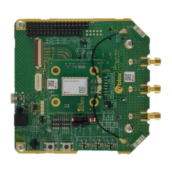
Coaxial cables with U.FL connectors connecting the module board’s RF traces to the • carrier board’s RF traces. Antennas connected to the carrier board’s SMA connectors. • Figure 3: Definition of Module board and Carrier board Document Information Page 19 of 31 FSS JODY-W263 Integration Instructions Rev 02.docx www.foresightsports.com... -
Page 20: Rf Trace Pcb Routing
Wi-Fi operation in the 2.4 GHz band and Wi-Fi operation in the 5 GHz band, the module has been tested and approved for use with antennas up to 2 dBi antenna gain. Document Information Page 20 of 31 FSS JODY-W263 Integration Instructions Rev 02.docx www.foresightsports.com... - Page 21 The antenna ports shown in Figure 4 on the right hand side are from top to bottom: ANT1, ANT0, and ANT2. ANT2 is not used and shall be left unconnected. Figure 6: Module board Antenna micro strip implementation Document Information Page 21 of 31 FSS JODY-W263 Integration Instructions Rev 02.docx www.foresightsports.com...
- Page 22 The carrier board RF traces includes pi network matching components and are routed as coplanar microstrips. Here 10 pF capacitors in series are implemented. Figure 8: Carrier board Antenna micro strip implementation Document Information Page 22 of 31 FSS JODY-W263 Integration Instructions Rev 02.docx www.foresightsports.com...
- Page 23 Figure 9: Component selection for RF matching network on carrier board using 10 pF series capacitors. Document Information Page 23 of 31 FSS JODY-W263 Integration Instructions Rev 02.docx www.foresightsports.com...
-
Page 24: Parts
Wi-Fi/Bluetooth antenna, Pulse W3006 Coax RF cable U.FL-2LP(V)-04N1-A-(40) Label and Compliance Information Label requirements 7.1.1 United States (FCC) This section contains the FCC compliance information for the JODY-W263-00B series modules. Model ISED certification number JODY-W263-00B 28505-JODYW263FSS Document Information Page 24 of 31 FSS JODY-W263 Integration Instructions Rev 02.docx... -
Page 25: Fcc Compliance Statement
7.1.2 FCC Compliance statement JODY-W263 module has modular approval and complies with Part 15 of the FCC Rules. Operation is subject to the following two conditions: 1. This device may not cause harmful interference, and 2. This device must accept any interference received, including interference that may cause undesired operation. -
Page 26: Ised Compliance Statement
JODY-W263-00B 28505-JODYW263FSS 7.1.4 ISED compliance statement JODY-W263-00B module complies with ISED (Innovation, Science and Economic Development Canada) license-exempt RSSs. Operation is subject to the following two conditions: 1. This device may not cause interference, and 2. This device must accept any interference, including interference that may cause undesired operation of the device. - Page 27 Modular Approval Requirements (Source: RSP-100 Issue 10), any application which includes the module must be approved by the module manufacturer (u-blox). The application manufacturer must provide design data for the review procedure. Document Information Page 27 of 31 FSS JODY-W263 Integration Instructions Rev 02.docx www.foresightsports.com...
-
Page 28: Product Testing
As all u-blox products undergo thorough in-series production testing prior to delivery, OEM manufacturers do not need to repeat any firmware tests or measurements that might otherwise Document Information Page 28 of 31 FSS JODY-W263 Integration Instructions Rev 02.docx www.foresightsports.com... -
Page 29: Go/No Go" Tests For Integrated Devices
JODY-W2 and the antennas should be arranged in a fixed position inside an RF shield box. The shielding prevents interference from other possible radio devices to ensure stable test results. Document Information Page 29 of 31 FSS JODY-W263 Integration Instructions Rev 02.docx www.foresightsports.com... -
Page 30: Information On Test Modes And Additional Test
⚠ The modular transmitter approval of JODY-W263, or any other radio module, does not exempt the end product from being evaluated against applicable regulatory demands. - Page 31 Label and compliance information is now section 7, Information on test modes and additional test is now section 9, additional test requirements is now section 10. Document Information Page 31 of 31 FSS JODY-W263 Integration Instructions Rev 02.docx www.foresightsports.com...
Need help?
Do you have a question about the JODY-W263 and is the answer not in the manual?
Questions and answers