Table of Contents
Advertisement
Quick Links
Advertisement
Table of Contents

Summary of Contents for Aim PDM 32
- Page 1 PDM 32 User Manual VER 1.06...
-
Page 2: Table Of Contents
Summary The PDM 32 ............................3 Connections ............................4 AMP connectors ........................... 5 Surlok connector .......................... 5 Rosenberger LVDS connector......................6 Standard compliances .......................... 6 Installation ............................7 Status LEDs ............................7 Inputs..............................8 Analog Inputs ..........................9 Digital Inputs ..........................9 Power Outputs ........................... - Page 3 ECU Driver builder ........................50 The device window......................... 56 21.1 Online measure values forcing ....................56 CAN Output configuration ......................59 Appendix A – Connectors and Pinout ......................60 Appendix B – Mechanical Drawings......................62 www.aim-sportline.com - PDM 32 User Guide...
-
Page 4: The Pdm 32
SmartyCam The PDM 32 should only be configured and installed by qualified personnel as to ensure the correct wiring and connections for all the inputs and outputs. High levels of current are present and can result in overheating and may cause risk of damage or injury to personnel and/or equipment, if not installed correctly. -
Page 5: Connections
2. Connections The PDM 32 has 6 connectors: 1 Surlok Power Connector to connect to the +V battery 1 Rosenberger LVDS connector to connect the display (6” or 10”) 2 35 pins AMP connectors 2 Binder connectors, 5 and 3 pins, for the connection to the USB port and to the analog mirror camera www.aim-sportline.com... -
Page 6: Amp Connectors
Loom wires and connectors pin selection are very important. Be sure to select wire size according to load current specification. AMP connectors PDM 32 connectors mate with AMP 776164-1 (black) and AMP 776164-4 (grey). Connector terminal: AMP 770520-3. This is the gold-plated version rated up to 17A. Wire sizes qualified for this terminal are: 20AWG, 18AWG, 16AWG. -
Page 7: Rosenberger Lvds Connector
Rosenberger LVDS connector PDM has an external high-speed link used to manage remote display. This link is realized by AIM custom cable (FCCA 682000). Link transmits to remote display the TFT information and the status LEDs activity. On the other side receives from remote display light sensor data and push buttons status. Same link is used also to power the remote display making a simple and reliable connection. -
Page 8: Installation
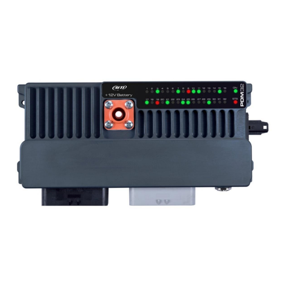
It must be installed in an aerated area and far from hot parts. 5. Status LEDs The PDM 32 has 32 status LEDs, one for every power output: • GREEN: the output is enabled, and its status is OK •... -
Page 9: Inputs
PDM without turning on the display. This can be useful for activating the Hazard, or keeping a fan on even with the engine off until the temperature reaches a correct value etc. • 2 speed inputs www.aim-sportline.com - PDM 32 User Guide... -
Page 10: Analog Inputs
In case an input is configured as Digital input, it is possible to enable an internal pull-up or pull-down resistance, depending on whether they are closed to ground or closed to VBatt, as shown in the following picture www.aim-sportline.com - PDM 32 User Guide... - Page 11 Multistable: Each time the connected button is pressed, the channel value changes from 0 to N (this value depends on the configuration), then returns to www.aim-sportline.com - PDM 32 User Guide...
-
Page 12: Power Outputs
Half Bridge. The max current that the PDM 32 may load is 120A: this value is related to High Side outputs use. When using bridge outs in Low Side mode, please calculate 17A for GND pin connected (4 GND pins available). - Page 13 All the outputs can be activated as PWM, with variable duty cycle and with some differences based on the outputs: - the L M H outputs have a fixed frequency of 100 Hz www.aim-sportline.com - PDM 32 User Guide...
- Page 14 In case of PWM mode selected on this out, soft start reaches user PWM value. • In B type outputs, there is also the possibility to set PWM frequency www.aim-sportline.com - PDM 32 User Guide...
-
Page 15: Power Outputs Protections
The starter motor now is activated and its rotation switches ON the vehicle Engine. When the engine is ON, PDM out must be disabled. Internal diode block reverse current that would flow from P4 (shorted to P2) to P1 and finally to PDM out. www.aim-sportline.com - PDM 32 User Guide... -
Page 16: High Power Output 1,2,3,4 Freewheeling Protection Diode
Low and High outputs do NOT have diode protection to protect against return current (voltage?) from inductive loads. It is recommended, if not necessary, that an external diode be used for such outputs. Inductive load examples include relays, solenoid valves, starter solenoids, and electric motors - including fans. www.aim-sportline.com - PDM 32 User Guide... -
Page 17: Powering
GND connections in this example are divided in GND for PDM logic and Low side function up to 34A, GND for external sensors reference and GND for AiM CAN BUS. Internally all GND pins are tied together but they are split in different pins, to eventually simplify the loom connection. -
Page 18: Other Devices
9. Other devices The PDM 32 may manage some external devices: Display Mirror camera Display The PDM32 supports one display. It may be 10” or 6” The connection is through a dedicated high frequency LVDS cable to connect to the Rosenberger connector at the side of the PDM: Please, refer to the section “Display Configuration”... -
Page 19: Gps
Gps 08 module is supplied with a standard male 712 Binder 5 pin plug, that needs to connect to Can0H (Aim Expansion Can ) (22) and Can0 L (11) with ground (10) , +VBext(32) and +Vbout (33) A 1 mt patch cable with a female 712 Binder inline socket is in the kit and should be wired as shown here. -
Page 20: Mirror Camera
The mirror camera is a small add-on that can be useful in some situations. You may connect it to the PDM through the 5 pin Binder connector To activate the mirror camera, please, refer to the “Trigger Command” section in this manual www.aim-sportline.com - PDM 32 User Guide... -
Page 21: Software Race Studio 3
Aim Software Race Studio 3 lets you execute the following activities: • Configure your PDM 32 • Transmit a new version of the firmware to your PDM 32 • Look ONLINE at all the data, power consumption, temperatures, Output status while your PDM 32 is installed on your vehicle •... -
Page 22: Channels And Variables
To select the protocol for connecting your PDM32 to the ECU of the vehicle CAN2 Stream To select the protocol for communicating with other devices through the CAN 2 CAN Expansion To manage other AIM devices, such as: RIO 02 https://www.aim-sportline.com/download/technical-sheets/aim_rio02_102.pdf GPS08 https://www.aim-sportline.com/en/products/gps08-module/index.htm... -
Page 23: Input Channels Configuration
PDM without turning on the display. This can be useful for activating the Hazard, or keeping a fan on even with the engine off until the temperature reaches a correct value etc. - 2 speed inputs www.aim-sportline.com - PDM 32 User Guide... -
Page 24: Analog Inputs Configuration
Sensor type Measure unit Sampling frequency Display precision: it configures how many decimal digits will be shown on the display It is possible to enable an internal 2kohm pull-up, as shown in the following picture: www.aim-sportline.com - PDM 32 User Guide... -
Page 25: Digital Inputs Configuration
0 to N (this value depends on the configuration), then returns to 0. Logged: if active, the system records the digital values, else they can be used and shown but they are not recorded. www.aim-sportline.com - PDM 32 User Guide... -
Page 26: Other Internal Sensors And Channels
The BIAS computes which channel between two is prevailing (typically used for suspensions or brakes) Bias with threshold CH1 / (CH1 + CH2) As above, but computed only when the two channels exceed a user configurable threshold www.aim-sportline.com - PDM 32 User Guide... -
Page 27: Status Variables Configuration
Different conditions for activation and deactivation It may be useful to have two different conditions for activating and deactivating a Status variable. For example, we need to turn ON a Status variable ON when Water Temperature www.aim-sportline.com - PDM 32 User Guide... - Page 28 This is the only case in which the Status variable assumes more than 2 values. An example may be the management of a rotary switch, connected to an analog input, as shown in the following picture: www.aim-sportline.com - PDM 32 User Guide...
-
Page 29: Trigger Commands
The “Create new Output Command” panel appears • Set the condition for activating the trigger command. As an example, let us activate the mirror camera when the gear is in reverse. As you see, it is very simple: www.aim-sportline.com - PDM 32 User Guide... -
Page 30: Power Outputs Configuration
In this case too, the soft start and soft stop are available. The square wave mode offers the possibility to define the frequency and duty cycle of the output and is used when the wave frequency is very low. www.aim-sportline.com - PDM 32 User Guide... - Page 31 Power Output Activation and Deactivation The conditions for activating and deactivating every output of the PDM 32 are completely configurable. First of all, it is possible to select one of the two modes: Same condition for both activating and deactivating.
-
Page 32: Power Output Related Channels
Example: Turn the fan ON when the water temperature reaches 100°C and turn the fan OFF when the water temperature decreases under 80°C 11.10 Power Output related channels Every Power Output has two associated channels: The Status The Instant Current drawing in it. www.aim-sportline.com - PDM 32 User Guide... - Page 33 At ON instant the output is activated. During the time T1, the output can source an inrush current higher than user set value: the PDM does not check the overcurrent but only the Short circuit. www.aim-sportline.com - PDM 32 User Guide...
-
Page 34: Pwm
Typical uses of PWM are: • Fan speed control • Water pump speed control (useful to maintain water temp close to ideal value) • Led and Bulb Lamp dimming (i.e. DRL dimming related to low beam status) www.aim-sportline.com - PDM 32 User Guide... - Page 35 In the range 80°C – 90°C the duty cycle is 50% If the water temperature is higher than 90°C, the duty cycle is 100%. The time for passing from one level to the next one is set at 5 seconds. www.aim-sportline.com - PDM 32 User Guide...
-
Page 36: Square Wave
This possibility may be useful when a device absolutely requires a PWM output at a specific frequency for working properly. 11.12 Square Wave The last way for managing the Power Output is the Square Wave, that may be useful for managing slow blinkings www.aim-sportline.com - PDM 32 User Guide... - Page 37 As shown in the above image, you may define the form of the wave, specifying how long the signal remains ON and how long it remains OFF. www.aim-sportline.com - PDM 32 User Guide...
-
Page 38: Ecu Connection And Configuration
PDM transmits this signal. Sometimes, and particularly when there are other devices in the network, the PDM should not transmit it: in this case, please, enable this flag, to make the PDM remain completely silent. www.aim-sportline.com - PDM 32 User Guide... -
Page 39: Can2 Stream Configuration
This page works exactly like ECU Stream one. Here you can find additional CAN modules. To load your additional module CAN protocol: enter “CAN2 Stream” tab • press “Change protocol” button • select “Manufacturer” and “Model” (in the example (MEGALINE/PADDLESHIFT) • press OK • www.aim-sportline.com - PDM 32 User Guide... -
Page 40: Can Expansions Configuration
Here you can select the CAN expansion you want to set. Select it and press OK. Each expansion needs to be set filling in the related panel. Please note: for any further information about AiM Channel expansion refer to the related user manual you can download from AiM website www.aim-sportline.com documentation area, products section. -
Page 41: Icons Manager Configuration
Once all Icons set “Icons page” shows the icons summary and mousing over an Icon the related panel shows up on the right of the page as shown here below. Here you can also edit and delete an icon using the related icons www.aim-sportline.com - PDM 32 User Guide... - Page 42 - PDM 32 User Guide...
-
Page 43: Display Configuration
16. Display configuration The PDM 32 may manage two different displays: The 6” and the 10”. You have to select which display you wish to connect through the proper software page: Then you may proceed with the display configuration, in order to have a maximum of 8 pages available. - Page 44 • drag and drop the channel you want to set in the desired field or double click on it www.aim-sportline.com - PDM 32 User Guide...
-
Page 45: Shift Lights And Alarms Configuration
LED stays ON if its threshold is exceeded a LED stays ON until another LED with higher threshold turns on or Link the shift lights to the engaged gear enabling the related checkbox. • www.aim-sportline.com - PDM 32 User Guide... -
Page 46: Alarm Leds Configuration
(“Untill” – 6) among: condition no longer met, the device is turned off, a button is • pushed, or data are downloaded “+” buttons you find right of the panel are to add new alarms (the top one) or to add new actions to an alarm • (bottom one) www.aim-sportline.com - PDM 32 User Guide... - Page 47 “Save” in “Create New Alarm Panel and you will come back to “Shift • Lights and Alarm” page www.aim-sportline.com - PDM 32 User Guide...
-
Page 48: Smartycam Stream Setting
18. SmartyCam stream setting The PDM 32 can be connected to AiM SmartyCam to show the data you wish on SmartyCam video. To set each channel: • click on it and a setting panel shows up • it shows all channels and/or sensors that fits the selected function •... -
Page 49: Managing A Track With Race Studio 3
Race Studio 3 database. It automatically updates at start up if a connection to the Internet is available. The column on the Right shows: • the data sheet of the selected track. www.aim-sportline.com - PDM 32 User Guide... - Page 50 • Delete All: delete all tracks stored in your PDM 32 memory • Save all: save all the tracks stored in your connected PDM 32; it creates a zip file you can load to another AiM device • Load Saved: load the tracks you previously saved in your connected PDM 32 memory www.aim-sportline.com...
-
Page 51: Ecu Driver Builder
You may use the CAN Driver Builder for producing a protocol that may be managed both on CAN 1 and on CAN2. In order to activate the DriverBuilder, press the following pushbutton: The main page is shown: and the following pushbuttons are available: Press "NEW" for creating a new protocol. This window appears: www.aim-sportline.com - PDM 32 User Guide... - Page 52 Protocols Database. In case the Device Manufacturer is not in the list, you can add it. - the Device Type: it can be ECU (in this case it can be managed only in CAN1 of the Aim Loggers/dashes) or...
- Page 53 If you enable the Row Counter, you must specify its Start Bit, its Number of bits and the Value for every single row to be defined. After having set the different parameters, you click OK and a new window appears: www.aim-sportline.com - PDM 32 User Guide...
- Page 54 - Conversion : for every channel you can define a Gain and an Offset ( Output = Input Value x Gain + Offset) or an Encoding. In this case, a conversion table is to be defined per every value of the field: www.aim-sportline.com - PDM 32 User Guide...
- Page 55 For modifying a channel, click on it. For adding another stream, click on the "+" at the right of the stream. For Sorting the measures in the stream, please, push the pushbutton and the window will appear: www.aim-sportline.com - PDM 32 User Guide...
- Page 56 PC with the Measure Protocol Key installed, the locked measures are completely visible, else they are hidden and crypted. At the end, "Save" and exit. You will find the new protocol among all the others in the database. www.aim-sportline.com - PDM 32 User Guide...
-
Page 57: The Device Window
21. The device window Clicking your PDM 32 bottom left of the software page you enter the device window and have these options: Live Measures: to check all PDM 32 channels; here you can: • start live measures sort the channel visualization as you prefer: as managed by the firmware (sort by configuration),... - Page 58 If you select a channel, RPM, for example, and click on the right small icon that appears near the value, you may force the value of that channel. The forced channels are shown surrounded by a red frame. Here, for example, RPM has been forced to the value 5000. www.aim-sportline.com - PDM 32 User Guide...
- Page 59 100°C. If you force its value at 100°C, and, using the “+” and “- “pushbuttons, you move this value up and down and you may see the alarm being turned ON and OFF. www.aim-sportline.com - PDM 32 User Guide...
-
Page 60: Can Output Configuration
1,2, 5, 10 or 20 Hz When all channels set your configuration is finished: • press “Save” on the page top keyboard • press “Transmit” to transmit the configuration to the PDM 32 www.aim-sportline.com - PDM 32 User Guide... -
Page 61: Appendix A - Connectors And Pinout
Appendix A – Connectors and Pinout www.aim-sportline.com - PDM 32 User Guide... - Page 62 - PDM 32 User Guide...
-
Page 63: Appendix B - Mechanical Drawings
Appendix B – Mechanical Drawings www.aim-sportline.com - PDM 32 User Guide...
Need help?
Do you have a question about the PDM 32 and is the answer not in the manual?
Questions and answers