Table of Contents
Advertisement
Quick Links
Advertisement
Table of Contents

Summary of Contents for Vision Tech XT890H Series
- Page 1 Service Manual for XT890HW Desktop POS Printer...
- Page 2 Record of Changes Version Date Content of Change Made by Reviewed Approved...
-
Page 3: Table Of Contents
Table of Contents Notes for Maintenance ..........................5 1. Characteristics of the Printer ......................... 1.1 Overview............................6 1.2 Main Characteristics.......................... 6 1.3 Technical Parameters ........................7 Appearance and Components ........................9 2.1 Outer Appearance of the Product ...................... 9 2.2 Connecting Diagram for Components of Control Panel. - Page 4 5.2 Printing..............................18 5.3 Paper Feed.............................. 19 5.4 Cash drawer ............................19 5.5 Indicator/Buzzer............................20 5.6 Communication............................20 5.7 Paper Cutting............................21 6. Dismantlement and Assembly of Main Parts ....................22 6.1 Dismantlement of the Printer........................22 6.1.1 Dismantlement of the base of the printer..................22 6.1.2 ..............
-
Page 5: Notes For Maintenance
Notes for Maintenance Prior to operation and use of the printer, read the following notes carefully: 1. Safety warning Warning: The printing head is a heating part, do not touch it or parts neighboring it while printing or when printing is just over. Warning: Do not touch the printing head and the connecting parts lest the printing head be damaged by static electricity. -
Page 6: Characteristics Of The Printer
1、Characteristics of the Printer 1.1 Overview This printer is a thermal note printer equipped with automatic cutter, it has the characteristics of high printing quality, high speed and high stability and it can be applied in commercial POS system and catering industry and so on widely where on-site real-time printing of notes is required. -
Page 7: Technical Parameters
1.3 Technical Parameters Model T890H Color White Printing mode Direct row-type thermal printing Printing speed 300mm/s Width of paper roll 58mm(57.5±0.5mm),80mm(79.5±0.5mm),83mm(82.5±0.5mm) Paper roll ID MinФ13mm, OD Max Ф83mm Thickness of paper 0.06-0.08mm Printing width 52/72/80±0.5mm (can be adjusted through command) Paper-out mode Front paper out Printing density... -
Page 8: Appearance And Components
Reliability Service life of the cartridge is 150 kilometers and that of the cutter is 2 million times Paper-cutting mode Semi-cutting Paper detection Photoelectric sensor Black-label positioning Supported Input buffer 2048Kbytes NV Flash 256Kbytes Voltage input of adaptor AC 100-240V/50~60Hz Voltage output of adaptor DC 24V/2.5A Control of Cash drawer... -
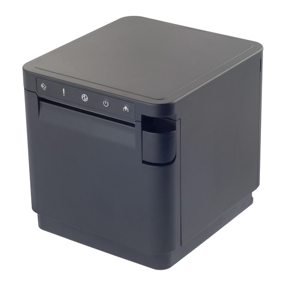
Page 9: Connecting Diagram For Components Of Control Panel
2.1 Appearance of the Product 1--Power light 2--Status indicator light 3-- Low paper indicator 4--Fixed knife assembly Partition board Rubber roller Cutter and moving knife set Cover-opening button Flip cover Base 10-- Gear of rubber roller 11-- 12--Black mark sensor 13--Back cover 14--Main body 15--Paper feed button... -
Page 10: Interfaces Of The Printer
The printer composed of main control board, printing cartridge, cutter, keys and buttons is connected to the mainboard via connectors or pinboard, Below is the connection diagram for the control board components: Fig 2.2.1 Connection Diagram of USB+ Network Interface Control Panel Fig 2.2.2 Position Diagram for USB+ Network Interface Control Panel 2.3 Interfaces of the Printer... -
Page 11: Interface For Cash Drawer
2.3.1 Power interface SIGNAL NAME +24V SHELL 2.3.2 Interface of Cash drawer Cashier-box control: 6-line RJ-11 socket, output DC 24V/1A power signals to drive actions of Cash drawer. SIGNAL NAME FGND Drawer 1 CASH Drawer 2 654321 2.3.3 USB interface... -
Page 12: Serial Interface
SIGNAL NAME VBUS D- (DATA-) D+ (DATA+) 2.3.4 Serial interface SIGNAL NAME 2.3.5 Network interface... -
Page 13: Keys, Buttons, Indicators And Functions
SIGNAL NAME GREEN+ GREEN - YELLOW+ YELLOW- 3、Keys, Buttons, Indicators and Functions... -
Page 14: Paper Feed Key
3.1 Paper-feed key ( When the printer does not alarm, press the key to feed paper, and hold it to feed paper continuously. 3.2 Power key ( Press this key 1-2 seconds to turn on/off the printer. 3.3 Power indicator ( The indicator light is blue in color. -
Page 15: Installation And Use
Including overheating of the printing head, cover opening, paper lacking, cutter jam and paper jam, etc. Standby status No error, no printing, no paper feed, waiting for printing task of the printer. Printing status The process from start to end of printing the contents after the printing contents are received. Paper-out status The process from paper out to paper cutting after printing is over. -
Page 16: Connecting To Cable
2) While inserting or pulling the plug of the power adaptor, be sure to hold the connector's housing of the plug, and avoid pulling the cable with force; 3) Avoid dragging the cable of the power adaptor, or the cable may be damaged and a fire or electrical shock may be caused;... -
Page 17: Guide On Trouble-Shooting
1.Card slot 1 2. Card slot 2 3. Partition board Choose a suitable position according to the width of the paper, and insert the partition board downward vertically (Note: the partition board is mounted at the position of card slot 1 by default) Notes: The partition board is in card slot 1: The paper roll with width of 80mm(79.5±0.5mm) is supported. -
Page 18: Printing
connected properly Power indicator AC/DC power adaptor is in fault Change the power adaptor is not on Power supply circuit on the Repair or change the mainboard mainboard is in fault Lamp panel is in fault Repair or change the lamp panel 5.2 Printing Fault Possible cause... -
Page 19: Cash Drawer
is not normal Motor of the printing head is in fault Change the printing head Foreign matter in the gear Clean the gear 5.4 Cash drawer Fault Possible cause Solution Cable for Cash drawer does not meet Replace cable with corresponding specification the specification Cash drawer cannot Change the cable... -
Page 20: Communication
The key or indicator is damaged Change the key or indicator Status display circuit is damaged Change or repair the mainboard The Buzzer is damaged Change the buzzer Buzzer does not Control circuit of the buzzer is nor Change or repair the mainboard work normal The setting is not correct... -
Page 21: Dismantlement And Assembly Of Main Parts
Scraps of paper are accumulated Clean the scraps on transmission parts Plate of driving head is over-heated Lower heating power of the driving head Paper is jammed Align edge of paper with the paper slot and put Paper feed position is not correct the paper between the rubber roller and TPH Blade is damaged or worn Change the cutter... -
Page 22: Dismantlement Of The Printer
3) In the process of handling the printing cartridge and electronic elements, taking anti-static measures; 4) Do not let parts such as screws keep inside the printer in the dismantlement process; 5)Prevent from doing harm to the printing cartridge in dismantlement and assembly. Maintenance tools: Phillips screwdriver and combination pliers Auxiliary materials: Lubricant, alcohol, absorbent ball and high-temperature adhesive tape 6.1 Dismantlement of the Printer... -
Page 23: Removing The Rear Cover And Main Body Of The Printer
6.1.2 Removing the rear cover and main body of the printer Picture Illustration Remove the back cover. - Page 24 First remove the 7P cable connected to the motherboard, then move the bottom of the main body away by hand, then lift the main body up, and finally gently remove the main body.
-
Page 25: Remove The Blade, Light Board, And Button Stickers On The Main Body
6.1.3 Remove the blade, light board, and button stickers on the main body Picture Illustration Use a small Phillips screwdriver to remove the 2 CA2.2*3.5 screws that secure the blade, and then take out the blade. Use a small Phillips screwdriver to remove the 2 PWB2*4*∮4.8 screws securing the light board, and then take out the light board. -
Page 26: Remove The Printer Interface Iron Plate, Main Board And Interface Board
6.1.4 Remove the printer interface iron plate, main board and interface board Picture Illustration Use a Phillips screwdriver to remove the 4 PA3*8mm screws that fix the interface iron plate, and then remove the interface iron plate and the main board. Remove the motherboard. -
Page 27: Remove The Cover Button, Flip Cover
Use a Phillips screwdriver to remove the 2 H3*6mm screws securing the interface iron plate, and then remove the interface plate. Use a Phillips screwdriver to remove the 2 H3*6mm screws that lock the left/right brackets. 6.1.5 Remove the cover button, flip cover Picture Illustration A:Use a small Phillips screwdriver to... - Page 28 Lift the cover open button upwards. Lift the flap upwards.
-
Page 29: Assembly Of The Printer
6.2 Assembly of the Printer Assembly is just the reverse sequence of dismantlement. -
Page 30: Cleaning Of The Printer
7、Cleaning the Printer Dust, foreign matters, sticky substance or other dirt struck on the printing head or inside the printer may lower printing quality. Clean the printer with the following method. Clean the Printing Head 1) Open the flip cover of the printer, and clean the printer from its center to the two sides with a cleaning pen or a cotton stick moistened with diluted alcohol (alcohol or isopropanol). -
Page 31: Appendix: Exploded View Of The Printer
Appendix: Exploded View of the Printer 1. List of Parts of the Printer Name of material Name of material back cover Fixed knife assembly main body paper bin motherboard Motor components Interface board switch plate shaft frame optocoupler components Interface iron plate optocoupler base Thermal film assembly... - Page 32 2. Explode View of the Printer 3. Explode View of Cartridge of the Printer...
Need help?
Do you have a question about the XT890H Series and is the answer not in the manual?
Questions and answers